HAL Id: inria-00400272
https://hal.inria.fr/inria-00400272
Submitted on 30 Jun 2009
HAL is a multi-disciplinary open access
archive for the deposit and dissemination of
sci-entific research documents, whether they are
pub-lished or not. The documents may come from
teaching and research institutions in France or
abroad, or from public or private research centers.
L’archive ouverte pluridisciplinaire HAL, est
destinée au dépôt et à la diffusion de documents
scientifiques de niveau recherche, publiés ou non,
émanant des établissements d’enseignement et de
recherche français ou étrangers, des laboratoires
publics ou privés.
Automatic translation of C/C++ parallel code into
synchronous formalism using an SSA intermediate form
Loïc Besnard, Thierry Gautier, Matthieu Moy, Jean-Pierre Talpin, Kenneth
Johnson, Florence Maraninchi
To cite this version:
Loïc Besnard, Thierry Gautier, Matthieu Moy, Jean-Pierre Talpin, Kenneth Johnson, et al.. Automatic
translation of C/C++ parallel code into synchronous formalism using an SSA intermediate form.
[Research Report] RR-6976, INRIA. 2009, pp.16. �inria-00400272�
a p p o r t
d e r e c h e r c h e
0 2 4 9 -6 3 9 9 IS R N IN R IA /R R --6 9 7 6 --F R + E N G Thème COMAutomatic translation of C/C++ parallel code into
synchronous formalism using an SSA intermediate
form
Loïc Besnard — Thierry Gautier — Matthieu Moy
∗— Jean-Pierre Talpin — Kenneth
Johnson — Florence Maraninchi
N° 6976
Centre de recherche INRIA Rennes – Bretagne Atlantique
synchronous formalism using an SSA intermediate form
Lo¨ıc Besnard , Thierry Gautier , Matthieu Moy
∗, Jean-Pierre Talpin , Kenneth
Johnson , Florence Maraninchi
∗ Th`eme COM — Syst`emes communicants´
Equipes-Projets Espresso
Rapport de recherche n° 6976 — June 2009 — 16 pages
Abstract: We present an approach for the translation of imperative code (like C, C++) into the synchronous formalism Signal, in order to use a model-checker to verify properties on the source code. The translation uses Ssa as an intermediate formalism, and the GCC compiler as a front-end. The contributions of this paper with respect to previous work are a more efficient translation scheme, and the management of parallel code. It is applied successfully on simple SystemC examples. Key-words: Program verification, virtual prototyping, formal modeling, synchronous approach
Traduction automatique de programmes C/C++ dans un
formalisme synchrone
R´esum´e : Nous proposons une m´ethode pour l’interpr´etation de programmes imp´eratifs (en C, C++) au moyen du formalisme synchrone Signal. Notre objectif est d’utiliser cette interpr´etation formelle afin de v´erifier des propri´et´es de programmes au moyen d’outils de model-checking. L’interpr´etation propos´ee utilise la repr´esentation interm´ediaire SSA (static single assignment) fournie par le com-pilateur GCC. Notre contribution est de d´emontrer l’efficacit´e de cette technique par la v´erification de programmes concurrents SystemC relativement simples.
Mots-cl´es : Verification de programmes, prototypage virtuel, mod´elisation formelle, approche synchrone
Contents
1 Introduction 4
1.1 Context and motivations . . . 4
1.2 An overview of Signal . . . 5
1.3 Ssa: an intermediate representation . . . . 5
2 Translating sequential code from Ssa to Signal 6 2.1 Ssato Signal: an example . . . . 6
2.2 Ssato Signal: translation scheme . . . . 7
2.3 C/C++ to Signal: implementation . . . 8
3 Modeling parallelism in the Ssa to Signal line 9 3.1 Presentation of SystemC . . . 9
3.2 Principle of the translation for SystemC code . . . 10
3.2.1 Isolation of system calls . . . 10
3.2.2 Addition of control signals . . . 11
3.2.3 Shared variables . . . 11 3.2.4 Inclusion in a simulator . . . 11 3.2.5 Possible extensions . . . 12 3.3 Experiments . . . 12 3.4 Discussions on performances . . . 13 4 Conclusion 13
4 Besnard, et al.
1
Introduction
1.1
Context and motivations
Nowadays, embedded systems are becoming more and more complex, with stronger and stronger constraints of many kinds: cost, reliability, short life-cycle, and so on. Design correctness of software and hardware functionalities of embedded system is one of the major challenges and priorities for designers using software programming languages such as SystemCand C/C++ to describe their systems. These programming languages allow for a comfortable design entry, fast simulation, and software/hardware co-design. Moreover, as the complexity of systems increases, designers are bound to reuse existing Intellectual Property components (IPs) in their design to improve the design productivity. However, system validation is a critical challenge for design reuse based on software programming languages. In recent years, many automated simulator and test tools have been developed to deal with design verification problems. However, mere simulation with non-formal development tools does by no means cover all design errors. What we therefore need is to use formal methods to ensure the quality of system designs. Among formal methods, model-checking has proved successful at increasing the reliability of some systems.
On the other hand, synchronous languages [BB91, BCE+03] have been introduced and used
successfully for the design and implementation of real-time critical software. They rely on math-ematical models such as data-flow equations or finite state machines that enable formal reasoning on designs. As a matter of fact, their associated toolsets provide formal transformations, automatic code generation, verification of properties. . .
Relying on these bases, we propose an approach in which we automatically translate C/C++ models into the synchronous formalism Signal [LGLL91, LTL03], hence enabling the application of formal methods without having to deal with the complex and error prone task to build formal models by hand. In particular, this allows one to use the Signal toolbox, which includes a code generator, a model-checker. . .
We base our approach and associated tool on previous studies for the translation of imperative languages to the synchronous data-flow language Signal [TLSG05, KTBB06]. This translation relies on the use of Ssa (“Static Single Assignment”) as intermediate representation of programs. Until now however, those previous works had not been seriously implemented nor experimented. Only manual experiments had been completed.
Moreover we extend the existing approach in two ways: first, the new translation scheme is more efficient, since it generates as few state variables as possible, thus reducing the work of the model-checker, and secondly, the tool now manages parallel, non-preemptive code.
As an example of such parallel language, we study the particular case of SystemC, a library for C++ for the high-level modeling of Systems-on-a-Chip, which provides among other things a non-preemptive scheduler for C++ processes.
The translation specified here was implemented in the Polychrony toolset [INRa]. Model-checking was successfully applied with the tool Sigali.
An approach that could be compared to ours, although different (uses neither Ssa nor syn-chronous formalisms) is that presented in [HFG08]. The authors define a semantic mapping from SystemCto Uppaal timed automata in order to get model checking for SystemC designs. It can be observed that our approach, thanks to the different strategies of code generation available for Signal programs [BGT09], also provide simulation code corresponding to the parallel SystemC description, including e.g. static scheduling code.
In this paper, we give in Section 1.2 an overview of the synchronous data-flow language Signal and in Section 1.3 a brief description of Ssa, which is the basis for our translation. The principles of the translation from Ssa to Signal and its implementation are described in Section 2. Then Section 3 addresses the addition of co-routine parallelism in the programs, using a SystemC flavour. Experimental results are provided for the model-checking of properties on some use case. Some concluding remarks are given in Section 4.
1.2
An overview of Signal
In Signal, a process P consists of the composition of simultaneous equations x := f (y, z) over signals x, y, z. A signal x ∈ X is a possibly infinite flow of values v ∈ V sampled at a discrete clock noted ^x.
P, Q ::= x := y f z | P where x | P | Q (Signal process)
The synchronous composition of processes P | Q consists of the simultaneous solution of the equations in P and in Q. It is commutative and associative. The process P where x restricts the signal x to the lexical scope of P .
[[P | Q]] = [[P ]] | [[Q]] and [[P where x]] = [[P ]]/x
An equation x := y f z denotes a relation between the input signals y and z and an output signal x by a combinator f . An equation is usually a ternary and infixed relation noted x := y f z but it can in general be an m + n-ary relation noted (x1, . . . xm) := f (y1, . . . yn). Such equations are built
with usual boolean or arithmetic operations such as or, and, not, =, <, +, ∗, . . .
In addition, Signal requires four primitive combinators to perform delay x := y$1 init v, sampling x := y when z, merge x = y default z and specify scheduling constraints x → y when ^z. The equation x := y f z where f = or, =, +, . . . defined the nthvalue of the signal x by the result
of the application of f to the nth values of signals y, z. All signals x, y, z are synchronous (have
the same clock): they share the same set of tags t1, t2, . . . .
The equation x := y$1 init v initially defines the signal x by the value v and then by the previous value of the signal y. The signal y and its delayed copy x are synchronous: they share the same set of tags t1, t2, . . . Initially, at t1, the signal x takes the declared value v and then, at tag tn, the
value of y at tag tn−1.
The equation x := y when z defines x by y when z is true (and both y and z are present); x is present with the value v2at t2 only if y is present with v2 at t2and if z is present and true at t2.
The equation x := y default z defines x by y when y is present and by z otherwise. If y is absent and z present with v1at t1then x holds (t1, v1). If y is present (at t2or t3) then x holds its
value whether z is present (at t2) or not (at t3).
The equation x → y when ^z forces the constraint that y cannot occur before x when z is present. In Signal, the presence of a value along a signal x is the proposition noted ^x that is true when x is present and that is absent otherwise. The clock expression ^x can be defined by the boolean operation x = x (i.e. y := ^x =defy := (x = x)). Specific operators are defined on clocks. For
instance, y ^+ z is the union of the clocks of signals y, z (x := y ^+ z =defx := ^y default ^z).
Clock expressions naturally represent control, the clock when x represents the time tags at which the boolean signal x is present and true (i.e. y := when x =defy := true when x). The clock
when notx represents the time tags at which the boolean signal x is present and false. We write ^0 for the empty clock (the empty set of tags).
A clock constraint E is a Signal process. The constraint e^= e′
synchronizes the clocks e and e′
. It corresponds to the process (x := (^e = ^e′
)) where x. Composition E | E′
, written also (| E | E′
|), corresponds to the union of constraints, and restriction E where x to the existential quantification of E by x.
A useful derived operator is the memory x := y cell z init v, that allows to memorize in x the latest value carried by y when y is present or when z is true (x := y cell z init v =def(| x :=
y default (x$1 init v) | x^= y ^+ (when z) |)).
1.3
Ssa
: an intermediate representation
A program is said to be in static single assignment (Ssa) form whenever each variable in the program appears only once on the left hand side of an assignment. Following [CFR+91], a program
is converted to Ssa form by replacing assignments of a program variable x with assignments to new versions x1, x2, . . . of x, uniquely indexing each assignment. Each use of the original variable
6 Besnard, et al.
ith assignment. For variables in blocks reachable by more than one program block, the φ operator
is used to choose the new variable value depending on the program control-flow. For example, x3= φ(x1, x2) means “x3takes the value x1when the flow comes from the block where x1is defined,
and x2otherwise”. This is needed to represent C programs where a variable can be assigned in both
branches of a conditional statement or in the body of a loop.
In this paper, we consider the Ssa intermediate representation of the GCC compiler (other modern compilers usually have a similar intermediate format). The compiler provides a language independent, locally optimized intermediate representation for C, C++, and Java programs where programming units such as functions and methods are transformed into a structure in which all native operations are represented by 3-address instructions x = f (y, z). A C program pgm is represented by a sequence of labeled blocks L:blk , where each block is a sequence of statements. Statements may be native method invocations x = f (y∗
) or branches if x goto L. Each block is terminated by either a return rtn or goto L statement. We summarised this representation in Figure 1. (program) pgm ::= L:blk | pgm; pgm (instruction) stm ::= x = f (y∗ ) (call) (instruction) stm ::= x = φ(y∗ ) (phi) | if x goto L (test) (block) blk ::= stm; blk | rtn (return) rtn ::= goto L (goto)
| return (return)
Figure 1: Intermediate representation for C programs
2
Translating sequential code from Ssa to Signal
2.1
Ssa
to Signal: an example
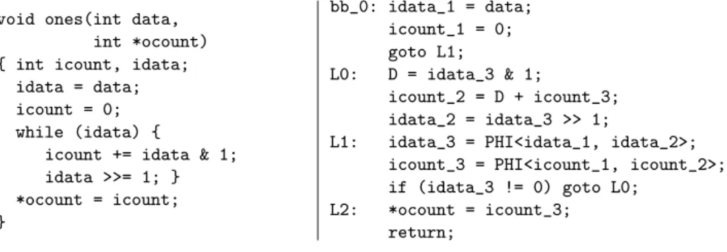
We depict the structure of the Ssa form of a typical C program, Figure 2. The function ones counts the number of bits set to 1 in a bit-array data. It consists of four blocks (labeled bb 0, L0, L1, L2). The block labeled bb 0 initializes the local state variable idata to the value of the input signal data and icount to 0. Then it passes control to the block L1. Label L1 evaluates the termination condition of the loop and passes control accordingly. As there are several possible sources in the control flow for the variables idata and icount, it determines the most recent value with the help of φ functions. If the termination condition is not yet satisfied, control goes to block L0, which corresponds to the actual loop contents that shifts idata right and adds its right-most bit to icount. If the termination condition is satisfied—i.e., all available bits have been counted—control goes to block L2 where the result is copied to the output signal ocount.
void ones(int data, int *ocount) { int icount, idata;
idata = data; icount = 0; while (idata) {
icount += idata & 1; idata >>= 1; } *ocount = icount; } bb_0: idata_1 = data; icount_1 = 0; goto L1; L0: D = idata_3 & 1; icount_2 = D + icount_3; idata_2 = idata_3 >> 1;
L1: idata_3 = PHI<idata_1, idata_2>; icount_3 = PHI<icount_1, icount_2>; if (idata_3 != 0) goto L0;
L2: *ocount = icount_3; return;
Figure 2: From C to static single assignment
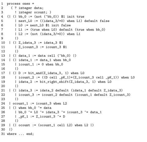
Figure 3 depicts the translation of function ones into Signal. Signals data and ocount are respectively input signal (line 2) and output signal (line 3) of the corresponding Signal process.
Lines 4–8 define the labels as boolean signals being true when control flow is in the corresponding block. For instance, bb 0 is true at the first instant, then it is false forever; L1 is true when either L0 or bb 0 is (control can go to L1 from L0 or bb 0). Note that there is no need to introduce a delay when control passes to L1. This is not the case for L0, for which there is a transition from L1 when the termination condition of the loop is not satisfied ((idata 3/ = 0) when L1): in that case, control will be in L0 at the next step.
Lines 14–15, 17–19 and 24 represent respectively the computations that are done in blocks bb 0, L0and L2: this is expressed by the sampling (when) on the corresponding boolean. Note that state variables are necessary to memorize the values of idata 3 and icount 3 (lines 10–11). Line 18, the operands of the plus operator have to be memorized at some common clock ( pk 1, line 27) since the arguments of the plus must be synchronous. The φ functions of block L1 are simply defined with merge (default) operators in Signal (lines 21–22).
1 process ones = 2 ( ? integer data; 3 ! integer ocount; )
4 (| (| bb_0 := (not (^bb_0)) $1 init true
5 | next_L0 := ((idata_3/=0) when L1) default false 6 | L0 := next_L0 $1 init false
7 | L1 := (true when L0) default (true when bb_0) 8 | L2 := (not (idata_3/=0)) when L1
9 |)
10 | (| Z_idata_3 := idata_3 $1 11 | Z_icount_3 := icount_3 $1 12 |)
13 | (| data_1 := data cell (^bb_0) |) 14 | (| idata_1 := data_1 when bb_0 15 | icount_1 := 0 when bb_0 16 |)
17 | (| D := bit_and(Z_idata_3, 1) when L0
18 | icount_2 := ((D cell _pK_1)+(Z_icount_3 cell _pK_1)) when L0 19 | idata_2 := bit_right_shift(Z_idata_3, 1) when L0
20 |)
21 | (| idata_3 := idata_2 default (idata_1 default Z_idata_3) 22 | icount_3 := icount_2 default (icount_1 default Z_icount_3) 23 |)
24 | ocount_1 := icount_3 when L2 25 | (| when bb_0 ^= data
26 | bb_0 ^= L0 ^= idata_3 ^= icount_3 ^= data_1 27 | _pK_1 := Z_icount_3 ^+ D
28 |)
29 | (| ocount := (ocount_1 cell L2) when L2 |) 30 |)
31 where ... end;
Figure 3: From Ssa to Signal
2.2
Ssa
to Signal: translation scheme
A general scheme for the translation is described Figure 4 with a function I[[pgm]], defined by induction on the formal syntax of pgm.
The present value of a signal is noted x, its next value is noted x′
. With each block of label L ∈ Lf in a given function f , the function I[[pgm]] associates an input clock xL, an immediate
clock ximm
L and an output clock x exit
L (note that all these clocks are not necessarily generated in
the effective translation). The clock xL is true iff L has been activated in the previous transition
(by emitting the event x′
L). The clock x imm
L is set to true to activate the block L immediately.
The clock xexit
L is set to true when the execution of the block labeled L terminates. The default
8 Besnard, et al.
(1) of Figure 4). The block blk is executed iff the proposition xL∨ ximmL holds, meaning that the
program counter is at L.
For a return instruction or for a block, the function returns a Signal process P . For a block instruction stm, the function I[[stm]]e1
L = hP ie2 takes three arguments: an instruction stm, the label
L of the block it belongs to, and an input clock e1. It returns the process P corresponding to the
instruction and its output clock e2. The output clock of stm corresponds to the input clock of the
instruction that immediately follows it in the execution sequence of the block.
Rules (1-2) in Figure 4 are concerned with the iterative decomposition of a program pgm into blocks blk and with the decomposition of a block into stm and rtn instructions. In rule (2), the input clock e of the block stm; blk is passed to stm. The output clock e1of stm becomes the input
clock of blk . (1) I[[L:blk ; pgm]] =I[[blk ]]xL∨x imm L L | I[[pgm]] (2) I[[stm; blk ]]e
L=let hP ie1 = I[[stm]]eLin P | I[[blk ]] e1 L
(3) I[[if x goto L1]]eL=hGL(L1, e ∧ x)ie∧¬x
(4) I[[x = f (y∗
)]]e
L=hE(f )(xy ∗
e)ie
(5) I[[goto L1]]eL=(e ⇒ xexitL | GL(L1, e))
(6) I[[return]]e L=(e ⇒ (x exit L | x exit f ))
where GL(L1, e)= if L1it is after L in the control-flow then e ⇒ ximmL1 else e ⇒ x ′ L1
E(f )(xyze)=e ⇒ (ˆx | x = [[f ]](y, z)), ∀f xyze
Figure 4: Translation scheme
The input and output clocks of an instruction may differ. This is the case, rule (3), for an ifx goto L1 instruction in a block L. Let e be the input clock of the instruction. When x is false,
then control is passed to the rest of the block, at the output clock e ∧ ¬x (intersection of clocks e and ¬x). Otherwise, the control is passed to the block L1, at the clock e ∧ x.
There are two ways of passing the control from L to L1at a given clock e. They are defined by
the function GL(L1, e): either immediately, by activating the immediate clock ximmL1 , i.e., e ⇒ x
imm L1
(the notation e ⇒ P means: if e is present then P holds); or by a delayed transition to L1at e, i.e.,
e ⇒ x′
L1. This choice depends on whether L1 is after L in the control flow, i.e. whether the block
L1 can be executed immediately after the block L.
Rule (4) is concerned with the translation of native and external function calls x = f (y∗
). The generic translation of f is taken from an environment E(f ). It is given the name of the result x, of the actual parameters y∗
and of the input clock e to obtain the translation of x = f (y∗
). This translation works when there is only one call to f at the same time. Recursive calls of f would require an explicit stack, and parallel calls would require duplicating the generated code for f for each thread. The generic translation of 3-address instructions x = f (y, z) at clock e is given by E(f )(xyze).
Instructions goto and return, rules (5-6), define the output clock xexit
L of the current block L
by their input clock e. This is the right place to do that: e defines the very condition upon which the block actually reaches its return statement. A goto L1 instruction, rule (5), passes control to
block L1unconditionally at the input clock e by GL(L1, e). A return instruction, rule (6), sets the
exit clock xf to true at clock e to inform the caller that f is terminated.
2.3
C/C++ to Signal: implementation
Signal models are automatically generated from C/C++ component descriptions with the help of the GNU Compiler Collection (GCC) [Fre] and its static single assignment (Ssa) intermediate representation [GCC03, The]. This is obtained in three main stages, as described below:
1. Converting C/C++ into Ssa: The first step of the translation scheme consists in converting C/C++ models into the Ssa form. This step is performed by GCC, which goes through several intermediate formats (Gimple Trees, then Control-Flow Graph (CFG)), and then produces the Ssa form which is used by GCC for optimizations.
2. Converting Ssa into Signal: The next step of the translation scheme consists in converting Ssa into Signal processes. It is implemented in the GCC front-end. The output of this step is a Signal program, syntactically correct but semantically not correct, which reflects directly the Ssa code in a Signal syntax. The implementation of the Signal generation is inserted in the GCC source tree as an additional front-end optimization pass. GCC currently features over fifty optimization passes. It can be chosen to use all of these by inserting this additional pass at the very end, but it may also make sense to exclude some of the optimizations. The resulting syntactic Signal program is another view of the Ssa code without any transformation (so the connexion to some other C compiler with an Ssa internal representation would be easily possible). This code is composed of a set of labeled blocks, composed of a set of φ definitions, a set of computations, and a branching.
3. Transforming the Signal program: The next step consists in the definition of (i) the control induced by the references to the labels in the branching statements; (ii) the memories induced by the loops and the control. The control is given first to the first block (through the signal bb_0 in the function ones example).
3
Modeling parallelism in the Ssa to Signal line
The previous section described a translation of sequential, imperative code, into Signal. We now present a way to extend this translation scheme to parallel code. We consider the case of co-routine semantics (i.e. non-preemptive scheduling with a single processor).
SystemC is an example of an execution platform with co-routine semantics. It is built on top of the C++ language, augmented with a scheduler, and communication and synchronization primitives. We implemented a translation from a small subset of SystemC which has basically two elements with respect to parallelism: pieces of code to be executed “atomically”, and a yield() instruction, that stops the execution of a thread, and yields the control back to the scheduler. The scheduler then elects any thread, non-deterministically.
The official SystemC library doesn’t have a yield() instruction, but this instruction can be implemented either with a slight modification of the scheduler as proposed by Claude Helmstet-ter [Hel07], or more simply by a wait(random(), SC NS);. The motivation for choosing yield() instead of the usual wait() statements of SystemC is to start with the simplest scheduling, to keep the focus on the notion of parallelism. We will show latter that implementing an arbitrary scheduling policy on top of this is possible.
In this subset of SystemC, we do not have any specific communication and synchronization primitives, but processes can communicate using shared variables.
3.1
Presentation of SystemC
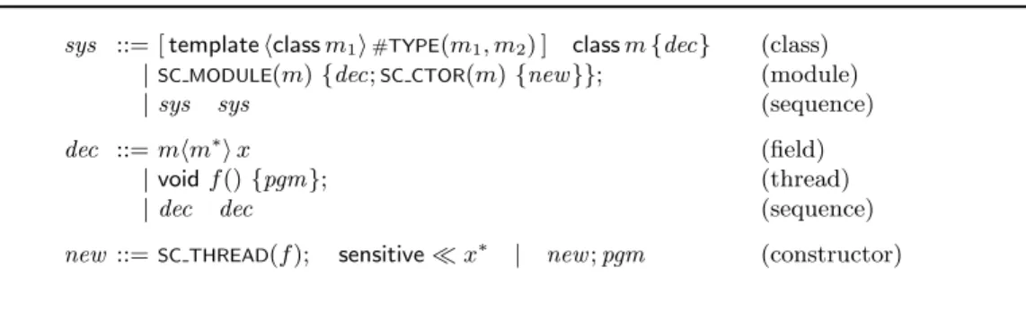
The core of the SystemC syntax relevant to the present study is represented in Figure 5. A system consists of the composition of classes and modules sys. A class declaration class m {dec} associates a class name m with a sequence of fields dec. It is optionally parameterized by a class with template hclass m1i. To enforce a strong typing policy, we annotate the class parameter m1with #TYPE(m1, m2) to denote the type of m1with the virtual class m2. A moduleSC MODULE(m) is a class
that defines an architecture component. Its constructor SC CTOR(m) {new ; pgm} allocates threads
(e.g. SC THREAD(f )) and executes an initialization program pgm. Modules define threads whose
execution is concurrent. Declarations dec associate locations x with native classes or template class instances mhm∗
i, and procedures with a name f and a definition pgm. pgm can be any C++ code. We assume x to denote the name of a variable or signal and to be possibly prefixed as m :: x by the name of the class it belongs to.
10 Besnard, et al.
sys ::= [ template hclass m1i#TYPE(m1, m2) ] classm{dec} (class)
|SC MODULE(m) {dec;SC CTOR(m) {new }}; (module)
| sys sys (sequence)
dec ::= mhm∗i x (field)
| void f () {pgm}; (thread)
| dec dec (sequence)
new ::=SC THREAD(f ); sensitive≪ x∗ | new; pgm (constructor)
Figure 5: Abstract syntax for SystemC
A simple example in given in Figure 6. It defines two n-bits counters in parallel. The macro DECLARE COUNTERdeclares n boolean state-variables bi, the function step performs one step
(apply-ing next(bi) = bixor ci−1and ci = bi and ci−1, cibeing the carry), and the macro BEGINNING OF PROCESS
declares the local variables ci. Each counter comes with two additional variables ... started and
... finished, maintained up to date by step(), that are true respectively after the counter did its first step, and once each bit of the counter is true.
SC_MODULE(module) { DECLARE_COUNTER(count1_); DECLARE_COUNTER(count2_); void compute1() { BEGINNING_OF_PROCESS; while(!(count2_started)) { yield(); } while(!(count1_finished)) { step(count1_); yield(); } ASSERT(count2_finished); } void compute2() { BEGINNING_OF_PROCESS; while(!(count2_finished)) { step(count2_); } } SC_HAS_PROCESS(module); module(sc_module_name name) { INIT_COUNTER(count1_); INIT_COUNTER(count2_); SC_THREAD(compute1); SC_THREAD(compute2); } };
Figure 6: Parallel counters
3.2
Principle of the translation for SystemC code
In SystemC, the bodies of processes are described using plain C++ code (plus function calls to the SystemC API, i.e. yield in our example). As a consequence, the translation from C/C++ to Signalcan be reused for that purpose with a few adjustments, detailed in the following.
3.2.1 Isolation of system calls
First it can be noticed that GCC considers SystemC macros (including synchronization primitives (“system calls”) like yield as plain C++. As opposed to that, our approach requires a special handling of these macros in the Signal code. Thus they have first to be visible in the Ssa code generated for the SystemC threads. To this end, they have to be viewed by GCC as external function calls. This is the case, for instance, for the instruction yield used in the program of Figure 6: it is passed as such in the Ssa code.
However, if system calls are processed by GCC as usual external calls, they are not distinguished from other instructions in the Ssa code and they may appear among other computations in Ssa labeled blocks. A first requirement for being able to process system calls specifically in Signal is thus to isolate them in specific blocks in Ssa. This is an easy transformation that consists in breaking up the blocks containing system calls, while respecting the control flow. In the Ssa
to Signal transformation, it is implemented as the very first step of the transformations applied on the syntactic Signal code (see Section 2.3, step 3). In the resulting Signal translation, the label of the block containing a system call will be viewed as the activation clock of the call of the primitive. Then, suppose that l0, . . . , ln are the labels corresponding to the different calls of a given primitive (say yield, for instance) in a given thread, then the following signal: yield := (when l0) default . . . default (when ln) represents the clock at which control has to be returned to the scheduler, from a yield primitive, for the considered thread. Also, it is necessary to take into account that the block that follows a system call cannot be run in the same logical instant than this system call (the OS has to take the control). Thus, the signal representing the label of this block has to be delayed by one instant and additional memories may be required for some variables. 3.2.2 Addition of control signals
In the C to Signal translation, input and output signals of the Signal process resulting from the translation of a C procedure correspond to the parameters of the procedure. When translating a thread in a multi-thread context, a few input or output control signals have to be added, in order to communicate with the system. These signals are the following:
input signal running: This signal is defined by the system. It specifies the clock at which the process is actually running (the processor is attributed to this process). Remind that in the Signal code obtained from a Ssa form, each operation is sampled, either directly or recursively, by the clock corresponding to a given label (for instance, ocount 1 := icount 3 when L2). In the process corresponding to a thread, each label is additionally sampled by the signal running (for instance, L2 := (not (idata 3/=0)) when L1 when running).
output signal end processing: This signal is defined by the clock corresponding to the final block of the Ssa (for the example of Figure 3, it would be: end processing := when L2). This is the way for processes to inform the scheduler that a yielding instruction was reached, letting the scheduler decide which process to wake up after.
output signals corresponding to system calls in the thread: for example, a signal yield , as defined above, is produced, corresponding to the clock of the calls of the yield primitive in the thread. Other signals correspond to wait or signal primitives, for instance. If the primitives are not used in the process, their clock is the empty clock. These signals complement end processing in that end processing says whether a yielding instruction was reached, while other signals like yield tell which one.
These signals are added automatically in the translation when the application is a multi-threaded one. Note that another input signal, start, can be added if restart is possible. It is then used to replace the definition of the initial label of the process: bb 0 := (start default false) when running.
3.2.3 Shared variables
Care has to be taken for variables shared by different threads. First, when a variable is not declared in the procedure where it is used, GCC does not produce real Ssa for these variables: there is no creation of distinct instances for them, no φ function for merging their different definitions. They are considered as “virtual Ssa”. For these variables, the mechanism of partial definitions provided in Signal is used. Let x be such a variable and suppose one of its definitions is x = E in a Ssa block labeled li. The corresponding Signal definition will be: x ::= E when li (the use of ::= means that there are possibly other definitions for x). The shared variables are necessarily state variables in Signal, for which their previous value is kept, when they are not redefined.
3.2.4 Inclusion in a simulator
In order to validate the translation scheme described above, a mock-up scheduler is described in Signal. This scheduler contains a non-preemptive scheduler that attributes non-deterministically the processor to one process when several processes are ready to execute. This corresponds to
12 Besnard, et al.
the SystemC scheduler with the yield() instruction described above. In Signal, if conflict represents the clock at which there is a potential conflict for the attribution of the processor (several processes are ready), the running process is chosen by: pid := (any when conflict) default ..., where any is an input signal that can take any value. The scheduler manages the status of each one of the processes pi corresponding to the threads of the application. A Signal process
SET STATUSis associated with each pi, with state variables representing the current and next status
of pi (ready, running). The scheduler receives and uses the control signals that are produced in
the processes pi. For instance, the clock of the signal yield produced in some process pk defines
instants at which the next status of pk, whose current status is running, will be ready (so that the
scheduler will have to choose, non-deterministically, a new running process). Thus, in return, the scheduler defines the control signals running provided to each one of the pi’s. For a given pk, the
corresponding signal running represents the clock at which pk has the running status.
It is worth noticing that the control of a given application is represented very differently in Signal than it would be in some usual imperative parallel language. There is no explicit program counter, no imperative description of suspend or resume actions. The control is fully described by the clocks of the signals of the application. The Signal equations defining some process pi define
its behavior as invariant equations. We explained that all operations in pi are conditioned by a
given input signal running. Periods of time in which pi is not running (or is otherwise suspended)
correspond to the instants at which the signal running is absent. So that suspend/resume, for instance, is automatically handled through the clock of the signal running.
3.2.5 Possible extensions
The scheduler described above is very simple. With the signals running, and end processing, it can model a non-preemptive scheduler. By adding more signals between the scheduler and the processes, and a more complex state-machine in the scheduler, one can relatively easily model a more complex scheduler, like the complete scheduler of SystemC. Indeed, a similar approach was followed in the tool LusSy [MMM06] and could easily be adapted, since LusSy also uses a synchronous formalism to model the scheduler. The scheduler used in LusSy omits a few details of the actual scheduler specifications, but a more complete version is described in [TKVS08], and even this version is still only a dozen states, and could be modeled with a few tens of lines of code in Signal.
The main difference with the translation implemented in LusSy is that the later does not use SSA as an intermediate form, and is indeed less efficient for the translation of plain C++ code (a more detailed comparison of the tools is in progress and will not be detailed here).
3.3
Experiments
The example described in Section 3.1 (Figure 6) is used for basic experiments. The program is automatically translated into Signal via Ssa following the general scheme described above. Then simulation code (in C) is generated from the Signal program with the Polychrony toolset [INRa]. Traces have been added in the Signal program to be able to follow the simulation. The results are those expected, whatever is the choice of the scheduler.
Besides these first results, a main objective of the experiments is to demonstrate the possibility of formal validation of models using this methodology. We use again the same example (parallel
counters) to prove formal properties using model-checking. The first counter waits that the second
one has started counting to count also. At the end, it checks that the second counter has finished (property ASSERT(count2 finished)). Indeed, from the point of view of the first counter, when the second one has started, it has also terminated, so that the property is true. A variant of the program (parallel counters with variant) is when a yield() is introduced in the body of the loop of the second counter. In that case, it is possible to start the second counter without finishing it, and then the first counter can run till the end, so that the property is false.
The Signal compiler included in the Polychrony toolset allows for checking static properties such as contradictory clock constraints, cycles, null clocks, exclusive clocks. . . In order to check
dynamic properties, the Signal companion model-checker Sigali [INRb, MR] may be used. It
is an interactive tool specialized on algebraic reasoning in Z/3Z logic. Sigali transforms Signal programs into sets of dynamic polynomial equations that basically describe an automaton. Then it can analyze this automaton and prove properties such as liveness, reachability, and deadlock. The fact that it is reasoning only on a Z/3Z logic constrains the conditions to the boolean data type (true, false, absent). This is practical in the sense that true numerical verification very soon would result in state spaces that are no longer manageable, however it requires, depending on the nature of the underlying model, major or minor modifications prior to formal verification. For many properties, numerical values are not needed at all and can be abstracted away thus speeding up verification. When verification of numerical manipulations is sought, an abstraction to boolean values can be performed, that suffices in most cases to satisfy the needs. Note that the translation to the Sigali format is done after the so-called clock calculus completed by the Signal compiler. This clock synthesis allows to reduce significantly the number of constraints. Unfortunately, Sigali does not provide counter-examples for the system when the proof fails.
For the parallel counters example and its variant, all data types are boolean (and the mock-up scheduler has been encoded also using only boolean types). The results of the verification of properties using Signal and Sigali are those expected. Performances (time and size of the system) for obtaining the results are provided in Figure 7 for 2-bits and 8-bits versions of the counters (they are obtained using a reordering of variables in Sigali).
size time
program state var. states reach. states transitions 2-bits parallel counters
(property true) 24 224
36 116 0.15 s 2-bits parallel counters
with variant(prop. false) 25 225
107 359 0.27 s 8-bits parallel counters
(property true) 36 236
1.296 3.896 66 s 8-bits parallel counters
with variant(prop. false) 37 237
328.715 1.117.223 124 s
Figure 7: Performances for proving properties with Sigali
3.4
Discussions on performances
One common mis-conception about Ssa is that since multiple assignments to the same variable are translated into assignments to multiple intermediate variables, the explosion of the number of variables introduces a huge overhead. This paper shows that the explosion of the number of variables is indeed not a problem: most variables are encoded into temporary variables in Signal, and will be dealt with very efficiently by a model-checker (no additional nodes in BDDs). Our experiments show that the number of state variables does not explode.
On the other hand, one real advantage of this approach is that it creates very few transitions in the generated code. In the absence of loops, a portion of code between two yielding instructions is indeed encoded in one clock tick in the synchronous world. As opposed to this, a naive approach translating each instruction with an explicit control-point would generate huge automata, with a lot of control-points. The encoding of this automaton would introduce either a lot of Boolean state variables (with a one-hot encoding) or state variables with a large number of possible values. Our Ssa-based translation avoids this overhead.
4
Conclusion
We described the principle and implementation of a translation of imperative code into the syn-chronous data-flow language Signal. Using Ssa as an intermediate format, the translation is natural. Since the Ssa form we are using (the one of GCC) is very simple, the implementation
14 Besnard, et al.
does not have to deal with all the particular cases of the source language (C++), and can focus on optimizations and performances. We also showed that the extension to a simple model of paral-lelism was possible and relatively straightforward, and showed the way to encode a more complex scheduling policy.
The main limitation of the approach with respect to parallelism is that although the co-routine semantics (non-preemptive scheduling) is encoded as a natural extension of the sequential transla-tion, a preemptive scheduling, or even real parallelism, would be much harder to model faithfully with this principle.
Indeed, the main point of our approach is to encode a sequence of assignments, in one or several basic-blocks, into a single parallel assignment, within one clock tick. This turns the sequential piece of code into large atomic actions, which were not atomic in the original code. In other words, applying the translation naively would reduce the set of possible interleaving, thus reducing the set of possible behaviors, and missing bugs in the proof.
Applying the translation to real parallel code would therefore require identifying which portions of code can be considered atomic, and where to introduce preemption points. Each preemption point could then be encoded in the same way as the yield() instruction. Actually, identifying which section can be considered atomic, which instructions can permute and move from a section to another, is an active research domain (see for example [QRR04]).
Another limitation of the current implementation is that we currently manage only a small subset of SystemC. Modeling the scheduling algorithm itself would probably not be the most difficult part. One bigger difficulty is to take the architecture of the platform into account. For example, when one process writes wait(event); and the other writes event.notify();, the translation obviously has to take into account the fact that event is the same object in both cases. Another example is when one does a port.write(value); and the other a another port.read(): in this case, the translation has to depend on whether port and another port are bound together or not. Extracting such information from SystemC code requires a SystemC front-end, and not just a C++ one. Many such front-ends exist, like Pinapa [MMM05] used by LusSy, but none of them use Ssaas an intermediate representation.
Unfortunately, re-using an existing compiler to get both an SSA intermediate form and the architecture of the platform, linked together, is not easy [BGM+08]. The approach followed by
Pinapa does reuse an existing compiler, but relies partly on the fact that the intermediate format is a high-level abstract syntax tree. We are working on a new version of Pinapa that would use an Ssa-based compiler, but this requires a substantial rework of the approach, and a complete rewrite of the code itself.
References
[BB91] A. Benveniste, G. Berry. The synchronous approach to reactive and real-time systems.
Proceedings of the IEEE 79(9):1270–1282, Sep. 1991.
[BCE+03] A. Benveniste, P. Caspi, S. A. Edwards, N. Halbwachs, P. Le Guernic, R. de Simone.
The synchronous languages 12 years later. In Proceedings of The IEEE. Pp. 64–83. 2003. [BGM+08] L. Besnard, T. Gautier, F. Maraninchi, M. Moy, J.-P. Talpin. Comparative study
of approaches to semantics extraction and virtual prototyping of system-level models. Technical report, Verimag, Grenoble INP, France; IRISA, INRIA Rennes, France, 2008. http://www-verimag.imag.fr/∼moy/fotovp/rapport-fotovp.pdf.
[BGT09] L. Besnard, T. Gautier, J.-P. Talpin. Code generation strategies in the Polychrony envi-ronment. Research report RR-6894, INRIA, 2009.
http://hal.inria.fr/inria-00372412/en/
[CFR+91] R. Cytron, J. Ferrante, B. Rosen, M. Wegman, F. Zadeck. Efficiently computing static
single assignment form and the control dependence graph. ACM Transactions on
Pro-gramming Languages and Systems (TOPLAS) 13(4):451–490, 1991.
[Fre] Free Software Foundation. The GNU Compiler Collection. http://gcc.gnu.org. [GCC03] Proceedings of the 2003 GCC Developers Summit. Ottawa, Ontario Canada, 2003. [Hel07] C. Helmstetter. Validation de mod`eles de syst`emes sur puce en pr´esence
d’ordonnancements ind´eterministes et de temps impr´ecis. PhD thesis, INPG, Grenoble,
France, March 2007.
http://www-verimag.imag.fr/∼helmstet/these-fr.html
[HFG08] P. Herber, J. Fellmuth, S. Glesner. Model checking SystemC designs using timed au-tomata. In CODES/ISSS ’08: Proceedings of the 6th IEEE/ACM/IFIP international
conference on Hardware/Software codesign and system synthesis. Pp. 131–136. ACM,
New York, NY, USA, 2008.
[INRa] INRIA Espresso Team. Polychrony tool. http://www.irisa.fr/espresso/Polychrony.
[INRb] INRIA Vertecs/Espresso Teams. Sigali tool. http://www.irisa.fr/vertecs/Softwares/sigali.html. [KTBB06] H. Kalla, J.-P. Talpin, D. Berner, L. Besnard. Automated translation of C/C++ models
into a synchronous formalism. In Engineering of Computer Based Systems, 2006. ECBS
2006. 13th Annual IEEE International Symposium and Workshop on. Pp. 426–436. March
2006.
[LGLL91] P. Le Guernic, T. Gautier, M. Le Borgne, C. Le Maire. Programming Real-Time Appli-cations with Signal. Proceedings of the IEEE 79(9):1321–1336, Sep. 1991.
[LTL03] P. Le Guernic, J.-P. Talpin, J.-C. Le Lann. Polychrony for System Design. Journal for
Circuits, Systems and Computers 12(3):261–304, April 2003.
[MMM05] M. Moy, F. Maraninchi, L. Maillet-Contoz. Pinapa: An Extraction Tool for SystemC descriptions of Systems-on-a-Chip. In EMSOFT. Pp. 317 – 324. September 2005. [MMM06] M. Moy, F. Maraninchi, L. Maillet-Contoz. LusSy: an open Tool for the Analysis of
Systems-on-a-Chip at the Transaction Level. Design Automation for Embedded Systems, 2006. special issue on SystemC-based systems.
http://www-verimag.imag.fr/∼
moy/publications/springer.pdf
16 Besnard, et al.
[QRR04] S. Qadeer, S. K. Rajamani, J. Rehof. Summarizing procedures in concurrent programs. In
POPL ’04: Proceedings of the 31st symposium on Principles of programming languages.
Pp. 245–255. ACM, New York, NY, USA, 2004.
[The] The Tree SSA project. Tree-SSA. http://gcc.gnu.org/projects/tree-ssa.
[TKVS08] D. Tabakov, G. Kamhi, M. Vardi, E. Singerman. A Temporal Language for SystemC. In
Formal Methods in Computer-Aided Design, 2008. FMCAD ’08. Pp. 1–9. 2008.
[TLSG05] J.-P. Talpin, P. Le Guernic, S. K. Shukla, R. Gupta. A compositional behavioral modeling framework for embedded system design and conformance checking. International Journal
of Parallel Programming 33(6):613–643, 2005.
IRISA, Campus universitaire de Beaulieu - 35042 Rennes Cedex (France)
Centre de recherche INRIA Bordeaux – Sud Ouest : Domaine Universitaire - 351, cours de la Libération - 33405 Talence Cedex Centre de recherche INRIA Grenoble – Rhône-Alpes : 655, avenue de l’Europe - 38334 Montbonnot Saint-Ismier Centre de recherche INRIA Lille – Nord Europe : Parc Scientifique de la Haute Borne - 40, avenue Halley - 59650 Villeneuve d’Ascq
Centre de recherche INRIA Nancy – Grand Est : LORIA, Technopôle de Nancy-Brabois - Campus scientifique 615, rue du Jardin Botanique - BP 101 - 54602 Villers-lès-Nancy Cedex
Centre de recherche INRIA Paris – Rocquencourt : Domaine de Voluceau - Rocquencourt - BP 105 - 78153 Le Chesnay Cedex Centre de recherche INRIA Saclay – Île-de-France : Parc Orsay Université - ZAC des Vignes : 4, rue Jacques Monod - 91893 Orsay Cedex
Centre de recherche INRIA Sophia Antipolis – Méditerranée : 2004, route des Lucioles - BP 93 - 06902 Sophia Antipolis Cedex
Éditeur
INRIA - Domaine de Voluceau - Rocquencourt, BP 105 - 78153 Le Chesnay Cedex (France)
http://www.inria.fr