Characterization of Shear Stiffness and Cell Metabolism in
Chondrocyte-Seeded Self-Assembling Peptide Hydrogel
Scaffolds
by
Christina Marie Cosman
B.S., Mechanical Engineering, Massachusetts Institute of Technology, 2001
Submitted to the Department of Mechanical Engineering
in partial fulfillment of the requirements for the degree of
Master of Science
at the
MASSACHUSETTS INSTITUTE OF TECHNOLOGY
June 2003
© Massachusetts Institute of Technology, 2003. All rights reserved.
ASSACHUSETIS INSTITUTE OF TECHNOLOGY I
OCT -;;--2-00-3
]-LIBRARIES
Author ... ;-.... :-; ...
~... .
Department of Mechanical Engineering
/
Certified by ... -... ,. ... ;;''/. ... / ... {- ... ...
~,... ,: ..
~....
i •••• /.' •••••••••••••••••••••••/ d ' ,',/
l,/
(/
/i ;::::~~~r Alan J. GrodzinskyProfessor
ofBiological,~al and~chanical
EngineeringAccepted by ... .
~ Thesis Supervisor
~
*'
Ain A. Sonin Professor of Mechanical Engineering Chairman, Committee for Graduate Students
Characterization of Shear Stiffness and Cell Metabolism in Chondrocyte-Seeded Self-Assembling Peptide Hydrogel Scaffolds
by
Christina Marie Cosman
Submitted to the Department of Mechanical Engineering on May 8, 2003 in Partial Fulfillment of the Requirements for the Degree of Master of Science
ABSTRACT
Self-assembling KLD- 12 peptide hydrogels have previously been established as suitable scaffolds for chondrocytes for the purpose of generating a three-dimensional,
cartilaginous neo-tissue, which could potentially be implemented in the repair of in vivo chondral defects. Such tissue constructs have been shown to metabolically respond to dynamic compression by an increase in proteoglycan synthesis and glycosaminoglycan accumulation. For this thesis, modified chondrocyte-seeded, KLD-12 hydrogel
constructs have been developed and evaluated for the characterization of age-dependent shear mechanical properties and metabolic response to shear loading.
Based on previous research, a new casting frame and technique were developed to create 2 mm thick, KLD- 12 hydrogels for chondrocyte encapsulation. One day after casting, the total population in the hydrogel was 75-85% live, similar to the viability previously reported in 1.6 mm gels.
The equilibrium and dynamic shear stiffnesses of the constructs were determined over the course of 5-35 days post-casting. Methods for the application of pure shear deformation and the measurement of load response were similar to those previously used for cartilage explants. By Day 35, the average measured equilibrium and dynamic moduli were 8.0 ± 1 kPa and 67.7 ± 21 kPa, respectively. Thus, the construct stiffnesses were -3 orders of magnitude lower than explants in shear and -1-2 orders of magnitude lower than 1.6 mm constructs in confined compression.
A polysulfone (PSF) shear loading chamber was designed and fabricated to test the effect
of dynamic shear deformation on metabolism of chondrocytes in 2 mm KLD-12 hydrogels. In contrast to the stimulatory result in cartilage explants, cyclic shear
deformation caused a dramatic decrease in protein and proteoglycan incorporation in the KLD-12 constructs, compared to free-swell controls in culture plates. Notable increase in
GAG loss in both loaded and unloaded chamber specimens suggested that chamber
Validation studies of the shear chamber were conducted to determine the cause of biosynthetic suppression and GAG loss. The same phenomena occurred in a different
chamber with similar geometry, so the biocompatibility of PSF was investigated, via several shielding experiments. However, PSF was not proven to be toxic to
chondrocytes, and other factors in the chamber environment, such as gas diffusion or evaporation of culture medium, may have caused the catabolic effects.
Thesis Supervisor: Alan J. Grodzinsky
Acknowledgements
I joined the Continuum Electromechanics Lab as a senior undergraduate at MIT and liked it so much that I decided to stay for another degree! Indeed, being a part of this lab has been a joy and a privilege. My sincerest thanks go to Alan Grodzinsky for giving me a place in the group and being a supportive and inspiring advisor. Al's guidance and good humor make the lab a most unique one, both in its accomplishments and its
personality. Al's dedication to fostering interdisciplinary research helped me to bridge mechanical and biological engineering and to find a project that I was excited and challenged by.
Thanks also to all the lab members and visiting colleagues, who provided engineering knowledge, aid to my research, and an enjoyable work environment. It was wonderful to gain lasting friendships in addition to all those things. I am especially in debt to John Kisiday, a most attentive and encouraging mentor, who set a high standard for hard work and innovation in the lab and whose pioneering work with self-assembling peptide made my thesis possible.
Finally, I thank my dearest friends and family for guiding me in life and happiness. Their examples of excellence motivate me in every way.
Christina M. Cosman May 8, 2003
Contents
I
Introduction ...
12
1.1 Tissue engineering of cartilage ... 12
1.2 Articular Cartilage Composition... 13
1.3 Self-Assem bling Peptide Hydrogels ... 15
1.4 Shear Deform ation of Cartilage... 17
1.5 Thesis Objectives ... 19
2
Fabrication of Self-Assembling Peptide Hydrogels ...
21
2.1 Introduction... 21
2.2 M ethods...22
2.2.1 Cell Isolation... 22
2.2.2 Preparation of Peptide Solution... 22
2.2.3 D evelopm ent of N ew Casting Fram e... 23
2.2.4 Hydrogel Casting... 23
2.3 Results...25
2.4 Discussion... 26
3
Evaluation
of Shear M aterial Properties ... 273.1 Introduction... 27
3.2 M ethods...28
3.2.1 Specim en Preparation ... 28
3.2.2 M echanical Testing ... 28
3.2.3 Shear M odulus Calculation... 30
3 .3 R e su lts ... 3 1 3.4 Discussion... 34
4
Effect of Dynamic Shear Loading on Chondrocyte Metabolism ...
36
4.1 Introduction... 36
4 .2 M eth o d s...3 7 4.2.1 Development of Shear Loading Chamber for Hydrogel Disks...37
4.2.2 Shear Loading... 38
4.2.3 Biochem ical Analysis ... 40
4 .3 R e su lts ... 4 1 4.4 Discussion... 43
5 Validation of Polysulfone Loading Chambers... 45
5.1 Introduction... 45
5 .2 M eth o d s...4 6 5.2.1 Chamber Comparison ... 46
5.2.2 Application of Poly-HEM E Coating... 47
5.2.3 Use of Teflon Sleeve... 47
5 .3 R e su lts ... 4 8 5.4 Discussion... 53
6 Sum m ary and Future W ork... 55
6.1 Sum m ary... 55
6.2 Future W ork... 56
A ppendix A ... 59
A ppendix B ... 61
List of Figures
Figure 1 A schematic of the macromolecular structure of cartilage...14
Figure 2 A molecular model of a single KLD-12 self-assembling peptide,
exhibiting alternating hydrophilic (K, D) and hydrophobic (L) amino
acid residu es. ... . . 15
Figure 3 A scanning electron microscope image of the fiber structure of
KLD-12. The fiber diameter is about 5-10 nm and the pore size ranges from
5 0 -2 0 0 n m ... . . 16
Figure 4 A schematic of cartilage in various states of deformation. Confined
compression of cartilage induces fluid flow in addition to matrix
deformation (B), whereas shear strain causes deformation only (C). ... 18 Figure 5 The components of the casting frame for fabrication of 2 mm thick
hydrogel slabs... . 23
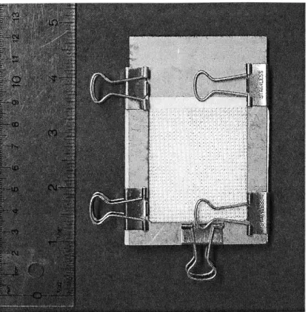
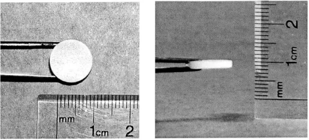
Figure 6 The casting fram e assem bly. ... 24 Figure 7 The top and profile views of a 2 mm thick, chondrocyte-seeded
KLD-12 hydrogel at D ay 30. ... 25
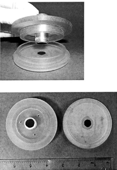
Figure 8 The chamber for applying torsional shear deformation. Patches of fine grit sandpaper on the base and top platen prevent the hydrogel disks
from slipp ing. ... . . 29
Figure 9 The intrinsic time-dependent stress relaxation response of a 30-day-old construct to successively applied ramp-and-hold shear strains...32 Figure 10 The peak and equilibrium shear stress of 30-day-old constructs in
response to ramp-and-hold shear strain. Both the peak and equilibrium shear stresses show a linear correlation with shear strain, with linear regression R2 values of 0.99 and 0.97, respectively...32
Figure 11 The average equilibrium shear modulus of constructs over time
(n=5-11). From Day 5 to Day 35, the modulus increased to 5.2±2 kPa. ... 33
Figure 12 A representative shear stress response of constructs to applied
sinusoidal shear strain at 0.5 Hz. The ~ 17 degree difference in phase angle the between stress and strain curves demonstrates the
viscoelastic behavior of the material, with elasticity being dominant
over viscous effects. ... 33
Figure 13 The average dynamic shear modulus of constructs over time (n=5-1 1).
From Day 5 to Day 35, the modulus increased to 67.7±21 kPa...34 Figure 14 A new shear polysulfone chamber for shear loading of the constructs.
Notable features include adjustable-height porous platens, large well
size, and top shear-axel attachm ent... 38
Figure 15 The incubator-housed loading apparatus for the precise application of compression and shear. The shear chamber containing tissue
constructs is wrapped to preserve sterility and mounted on the
In cu d y n ... . . 4 0
Figure 16 The 3H-proline and 3 5S-sulfate incorporation in dynamically sheared
(Sh), shear chamber free-swell (Sh FS), and 12-well plate free-swell (FS) constructs. Incorporation in sheared samples was significantly
lower (p<O.001) than in both other groups... 42 Figure 17 The 3H-proline and 3 5S-sulfate incorporation in dynamically sheared
(Sh), shear chamber free-swell (Sh FS), and 12-well plate free-swell (FS) constructs. Compared to chamber free-swell, incorporation in the
sheared disks was significantly higher (p<0.05), and both of those groups had significantly lower (p<0.001) incorporation than the
12-w ell free-s12-w ell controls. ... 42 Figure 18 The Teflon sleeve to be inserted in the polysulfone loading chamber...48
Figure 19 The 3H-proline and 3 5S-sulfate incorporation in compression chamber
free-swell (Cm FS), shear chamber free-swell (Sh FS), and 12-well plate free-swell (FS) constructs. Incorporation in the compression chamber was significantly lower (p<0.001) than in the shear chamber,
and both were much lower (p<0.001) than controls in the 12-well
p la te . ... 4 9
Figure 20 The 3H-proline and 3 5S-sulfate incorporation in shear chamber
free-swell (Sh FS), Poly-HEME-coated shear chamber free-free-swell (Sh Coat), 12-well plate free-swell (FS), and Ploy-HEME-coated 12-well plate free-swell constructs. Proline and sulfate incorporation levels were slightly lower (p<0.001 and p<0.05, respectively) in uncoated than in coated shear chamber samples. Incorporation in all shear chamber samples was significantly lower (p<0.001) than that in coated and uncoated 12-w ell controls... 50
Figure 21 The GAG content in the culture medium of shear chamber free-swell
(Sh FS), Poly-HEME-coated shear chamber free-swell (Sh Coat),
Teflon sleeve free-swell (Tef FS), and 12-well plate free-swell (FS) constructs. After 1 day in culture, shear chamber samples lost approximately 3 times more GAG than coated chamber disks. New medium from the second day in culture contained approximately twice as much GAG in the uncoated than in coated chamber samples. GAG levels in the Teflon sleeve medium remained similar to those of
12-w ell controls on both days... 51 Figure 22 The 3H-proline and 3 5S-sulfate incorporation in Poly-HEME-coated
shear chamber free-swell (Sh Coat), shear chamber free-swell (Sh FS), Teflon sleeve free-swell, and 12-well plate free-swell (FS) constructs. Only the proline incorporation in the coated chamber samples was slightly lower (p<0.05) than uncoated; sulfate incorporation levels between the two were not significantly different. Incorporation in Teflon sleeve and 12-well control samples was approximately 2-fold
higher than in coated and uncoated chamber samples. ... 51
Figure 23 The 3H-proline and 3 5S-sulfate incorporation in shear chamber
free-swell (Sh FS), Poly-HEME-coated shear chamber free-free-swell (Sh Coat), Teflon chamber insert free-swell (Sh Tef), and 12-well plate free-swell (FS) constructs. Incorporation was higher (p<0.05 and
p<0.001, respectively) in both coated chamber and Teflon insert
samples, compared to uncoated chamber samples. ... 52
Figure 24 The GAG content in the culture medium of shear chamber free-swell
(Sh FS), Teflon sleeve free-swell (Tef FS), Poly-HEME-coated shear
chamber free-swell (Sh Coat), and 12-well plate free-swell (FS)
constructs. After 1 day in culture, chamber free-swell medium had ... 52
Figure A-I The casting frame window component, made of stainless steel
(qu antity 1). ... . . 59
Figure A-2 The casting frame U-clamp component, made of stainless steel
(qu antity 2 ). ... . 60
Figure B-I The shear loading chamber base component, made of polysulfone
(qu an tity 1). ... . 62
Figure B-2 The shear loading chamber top component, made of polysulfone
(qu an tity 1). ... . . 63
Figure B-3 The alternate view of the shear loading chamber top component shown in F igure B -2 . ... . . 64
Figure B-4 A polysulfone platen-holder for a porous shear loading platen
List of Tables
Chapter 1
Introduction
1.1
Tissue engineering of cartilage
While the occurrence of severe articular cartilage injuries and resulting
debilitating conditions, such as osteoarthritis, are common among adults [1, 2], there is a lack of fully effective treatments to restore normal functionality to the affected joints. Current clinical and trial treatments include joint replacement [3], joint debridement, soft tissue grafting, osteochondral transplantation, allo- and autografting, and chondrocyte transplantation [4]. Though some of these procedures are promising, none has yet been able to produce long-term restoration of damaged articular surfaces and load-bearing joint function [4].
Tissue engineering techniques provide enormous potential for surpassing the efficacy of current treatments of cartilage defects. A prevalent paradigm in tissue engineering-based repair of articular surfaces is filling the defect volume with a three-dimensional cell-seeded biomaterial scaffold, which acts as a "living implant" that will integrate with the surrounding tissue and mimic its biochemical and mechanical
properties. Many researchers are working to optimize the scaffold materials,
morphologies, and culture conditions that will yield a superior neo-tissue. Potential materials may be composed of synthetic polymers [6-8] or natural fibers [9-12], both of which have unique advantages and disadvantages. Synthetic materials allow for
permeability, whereas natural materials may possess innate cell interaction capabilities and more inflammatory inertness [13]. Additionally, these scaffolds may be modified with bioactive molecules, such as growth factors or adhesion proteins, which may help to
govern their interaction with cells [4].
In conjunction with the scaffold material, the in vitro culture conditions of the cell-scaffold construct may play an important role in its performance in vivo. Culture of such neo-tissues prior to implantation allows the embedded cells to adjust to their new extracellular environment and resume their normal activity of extracellular matrix (ECM) synthesis, leading to the formation of new cartilage-like material within the scaffold. Over time, the mechanical strength of the construct increases, because of new ECM formation, and thus more closely resembles the mechanical properties of native cartilage
[8, 14, 15]. This pre-culturing may enhance the success of constructs as implants by
enabling them to better withstand physiological loads due to joint motion and weight bearing. Certain schemes of in vitro mechanical stimulation of constructs have been shown to stimulate chondrocyte biosynthesis, thereby augmenting their ECM production and accelerating tissue stiffening [16-21, 24]. Load conditioning may be a of great advantage to the development of tissue engineered implants, because it would reduce the in vitro culture time required for the constructs to attain physiological stiffness before implantation, thus reducing the risk of pre-transplant contamination.
1.2
Articular Cartilage Composition
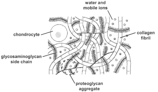
To engineer a tissue that is intended to mimic articular cartilage, one must understand the biochemical composition, physiological function, and mechanical behavior of the native tissue. Articular cartilage, which lines all the articulating joint surfaces of the body, has unique molecular constituents, which govern its lubricative and load-bearing functions. The tissue consists predominantly of a porous, solid matrix, made up of collagen fibrils (~20% wet weight, 50-65% dry) and proteoglycans (~5% wet weight, 25-35% dry), water (~75% wet weight), chondrocytes (2-10% by volume), and non-collagenous proteins, lipids and glycoproteins (-10% dry weight) [25-28, 30]. The
schematic in Figure 1 shows the main tissue components. The network of collagen fibrils, primarily type II, provides the tissue with tensile and shear strength and retains the proteoglycan molecules, whose negatively charged glycosaminoglycan side chains help to maintain osmotic swelling in the tissue, lending it compressive stiffness [31]. The spacing of collagen fibrils and the concentration of proteoglycans determine cartilage porosity [25].
Chondrocytes are responsible for the production and turnover of these ECM lTIolecules, via interactions with endogenous and exogenous soluble mediators and through the influence of mechanical forces [25, 32]. Given the proper culture conditions, chondrocytes will continue to generate ECM molecules, but their rates of biosynthesis depend on the specific biochemical and biomechanical environment. In the case of a severe cartilage defect in vivo, the avascular, alymphatic, and aneural nature of cartilage limits its ability to generate normally functioning repair tissue [33-35]. Damaged cartilage loses its load-bearing and lubricative capacity, thereby disrupting normal joint function and potentially leading to more serious degenerative conditions such as
osteoarthritis [37]. For this reason, finding an effective tissue engineering solution to cartilage repair would be extremely important.
chondrocyte
glycosaminoglycan side chain
water and
Figure 1: A schematic of the macromolecular structure of cartilage.
collagen fibril
1.3
Self-Assembling Peptide Hydrogels
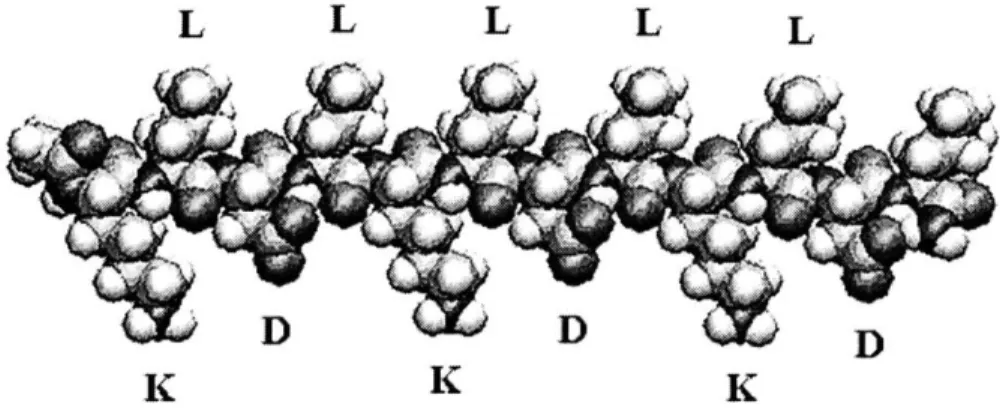
The self-assembling peptide hydrogel is a promising candidate for a cartilage tissue engineering scaffold material [15, 24, 35]. The primary structure of these peptides consists of short amino acid chains with repeating sequences of alternating hydrophobic and hydrophilic side groups, as shown in Figure 2 [38, 39]. This electronegativity scheme causes aqueous solutions of type I classified peptides to rapidly form P-sheet fibrils when exposed to physiologic ionic strengths and pH levels [32, 40, 41].
Photographed in Figure 3, the fiber diameter is fairly regular in the range of 5-10 nm [35] with a network pore size of 50-200nm [41]. The small fiber thickness, compared to most other polymer fibers [15] and the large amount of void space (> 99% water content) [32, 46] provide ample room for intercellular interaction and neo-matrix deposition. A major advantage of this type of peptide for use in biomaterial design is that different peptide sequences can be selected and easily synthesized, allowing one to tailor the material to specific applications [32], such as the engineering of cartilage.
L L L L L
D
DD
Figure 2: A molecular model of a single KLD-12 self-assembling peptide, exhibiting alternating hydrophilic (K, D) and hydrophobic (L) amino acid residues.
Figure 3: A scanning electron microscope image of the fiber structure of KLD-12. The fiber diameter is about 5-10 nm and the pore size ranges from 50-200 nm.
Several different peptide sequences have been tested for various cell culture applications [42, 43]. Specifically, the KLD-12 sequence has been investigated for chondrocyte compatibility and found to foster phenotypic stability and proliferation of chondrocytes encapsulated within its hydrogels, as well as cartilaginous ECM production and retention [15]. KLD-12 is a twelve amino acid, type I peptide with consecutive
repeats of Lysine, Leucine, Aspartic Acid, and Leucine, resulting in a +, 0, -, 0 charge
pattern under conditions near physiologic pH. Although the innate biochemical composition and mechanical strength (<1 kPa equilibrium modulus) of KLD-12 hydrogels [15] are very different from those of cartilage, over time, the cell-scaffold constructs increasingly resemble the natural tissue, both biochemically and mechanically, because of cumulative chondrocyte deposition and scaffold retention of new ECM [15].
From a tissue engineering perspective, this type of hydrogel is superior to
previous materials used for chondrocyte encapsulation [5, 17-19, 44, 45], in that it offers greater flexibility for molecular design, which could influence scaffold biodegradability, in vivo tissue integration, cell signaling, and biomolecular tethering [15]. Furthermore, synthetic scaffolds have less risk of carrying biological pathogens or contaminants than biologically derived scaffolds materials would [46].
1.4
Shear Deformation of Cartilage
The material behavior of cartilage stems from the interaction of its solid and fluid components. Classification of cartilage as a poroviscoelastic material takes into account its "biphasic nature", namely the flow of interstitial fluid relative to the solid ECM, whose intrinsic behavior is viscoelastic [47-49]. ECM viscoelasticity is thought to arise
from several molecular dynamics, including the mechanics of individual collagen molecules, inter-fibril sliding, and relative collagen-proteoglycan motion [50]. One
model is that bundled type II collagen molecules behave like parallel springs in tension, storing elastic energy, whereas viscous sliding between cross-linked collagen fibrils and between fibrils and proteoglycans dissipates energy nonlinearly [51, 52]. Another model
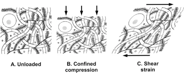
explains matrix viscoelasticity by lumping all collagen and proteoglycan molecules into their respective networks, each with its own nonlinear stress-strain behavior [29]. The poroviscoelastic model is most relevant to the case of compressive loading (Figure 4B), in which the solid matrix deforms immediately, resulting in increased fluid pressure within the tissue and forcing the interstitial fluid to flow to a region of lower pressure [53]. However, in the case of macroscopic shear deformations, such as simple and pure shear (Figure 4C), there is approximately no volumetric change in the tissue. Thus, intra-tissue fluid flow and pressure gradients would be negligible, and the material behavior could be described by the viscoelastic deformation of the solid matrix only [54-56].
Because of this phenomenon, shear loading of cartilage decouples matrix deformation from interstitial fluid flow and allows one to assess the effects of deformation alone on mechanical behavior and cellular processes [57]. Several experiments to characterize the shear mechanical properties of cartilage explants have confirmed the tissue's viscoelastic behavior under simple shear deformation [53, 57-59]. The tissue demonstrates a time-dependent stress relaxation response to a constant strain deformation, which is characteristic of viscoelastic behavior.
A. Unloaded B. Confined C. Shear
compression strain
Figure 4: A schematic of cartilage in various states of deformation. Confined compression of cartilage induces fluid flow in addition to matrix deformation (B), whereas shear strain causes deformation only (C).
Shear loading has also been applied to cartilage explants to test its effect on chondrocyte metabolism. These studies have been motivated by the goal of
understanding how the physiological forces, both compressive and shear, that articular cartilage experiences in vivo influence its material properties. Previous studies have showed that dynamic compressive loading of explants increased protein and proteoglycan synthesis in explants, hypothesizing that interstitial fluid flow, streaming potential, and mechanical deformation of cells and ECM were responsible [60, 61]. Dynamic shear loading of explants could elucidate which of those stimuli plays the largest regulatory role, by causing deformation in the absence of fluid flow [57]. Indeed, several studies have shown that certain dynamic shear loading protocols can increase protein and proteoglycan synthesis, suggesting that tissue deformation without fluid flow has this regulatory effect [35, 57, 62].
These findings in explants raise the question of whether similar shear loading protocols could have the same stimulatory effect on tissue engineered cartilage constructs. The analogy between explants and artificial tissue has been extensively investigated with compression loading schemes, and results have consistently been transferable [17-21, 24]. Corresponding studies employing dynamic shear loading have not been well documented, although Waldman et al. recently reported that intermittent cyclic shear deformation of cartilaginous tissue formed in vitro could significantly increase its equilibrium modulus and collagen and proteoglycan content, relative to
unloaded control levels [62]. This finding supports the need for exploring the effects of dynamic shear conditioning on other forms of engineered cartilage, such as KLD-12 constructs, which is a main objective of this thesis.
1.5
Thesis Objectives
Self-assembling KLD-12 hydrogels have previously been established as suitable environments for hosting chondrocytes in order to generate a three-dimensional,
cartilaginous neo-tissue, which could be implemented in the repair of chondral defects in vivo [15, 21, 24]. The motivation and background studies leading to the pioneering work with chondrocyte-seeded KLD-12 hydrogels is presented in Chapter 1 of this thesis. Kisiday et al. have developed fabrication and culture techniques for these unique hydrogels that are salubrious for chondrocyte viability, phenotypic stability, and biosynthesis. Furthermore, timelines of the histology, new matrix accumulation, and compressive mechanical properties of the construct have been documented,
demonstrating its biochemical and biomechanical similarity to natural cartilage.
In order to more fully characterize the mechanical integrity of this novel material, its shear material properties must be measured. Chapter 2 describes the considerations and processes used to create chondrocyte-seeded KLD-12 hydrogels that are suitable for shear loading. The fabrication and composition of constructs for shear loading are primarily the same as those previously used for compression tests, but the increased thickness of these gels causes some slight changes in experimental materials and
procedures. The shear equilibrium and dynamic moduli of these constructs could then be evaluated, and the details of these procedures are presented in Chapter 3.
Determining the effects of dynamic loading schemes on the metabolism of chondrocytes encapsulated in KLD-12 hydrogels requires imposition of several different kinds of loading that the constructs might experience in vivo, including both compression and shear. Certain dynamic compression duty cycles have been shown to increase
proteoglycan synthesis in the constructs, compared to free-swell controls, paralleling similar stimulatory results in explants [21, 23, 24]. A logical next step is to dynamically
shear the constructs in hopes that the explant analogy also holds for this type of loading.
If dynamic shear could augment protein synthesis in the constructs, as it did in explants
[57], then shear conditioning effects could be complementary to dynamic compression
induced proteoglycan stimulation. Combined loading modes could potentially build a stronger construct in a shorter time, thereby minimizing in vitro culture time and allowing earlier in vivo implantation. Hence, Chapter 4 describes preliminary attempts at shear conditioning of chondrocyte-seeded KLD-12 hydrogels. For these studies, a new loading chamber was manufactured, various loading protocols were tested, and subsequent biochemical assays were performed.
Results that dramatically opposed our hypothesis of anabolic stimulation due to dynamic shear prompted a series of studies to evaluate the adequacy of the new loading chamber as a bioreactor for this tissue-engineered material. Chapter 5 provides
background on this type of bioreactor chamber for cartilaginous tissue culture and reports on various validation experiments to elucidate its influence on the metabolism of
chondrocyte-seeded KLD-12 hydrogels.
A summation of the findings from all studies in this thesis and suggestions for
Chapter 2
Fabrication of Self-Assembling Peptide Hydrogels
2.1
Introduction
Kisiday et al. have successfully pioneered the development of self-assembling KLD-12 hydrogels as a scaffold for cartilage tissue engineering [15, 21-24]. The
cylindrical geometry of these constructs was designed to have 1.6 mm height, mimicking the thickness of in vivo articular cartilage, and 12.5 mm diameter to provide sufficient area for compressive loading and subsequent sample analysis. The functional
requirements for the constructs used in this thesis are slightly different, so the hydrogel geometry needed to be altered. A thicker gel was required for shear loading because a larger aspect ratio (thickness to diameter) would minimize the slippage of samples relative to chamber surfaces during application of simple shear deformation. A new casting frame was machined, such that it would yield 2 mm thick hydrogel slabs with slightly larger length and width, to allow the extraction of nine 12.5 mm diameter specimens. All experimental materials and procedures remained unchanged from those previously used [15, 24], except for the gelation time and casting frame disassembly. Because of the larger volume of cell-peptide solution needed to fill this new casting frame, the gelation process required a minimum of one hour to complete, to allow sufficient time for salt diffusion and peptide self-assembly. Resulting hydrogels also tended to stick to the flanking sheets of agarose-coated filter paper, so more sensitive frame removal was necessary to separate an intact slab.
2.2
Methods
2.2.1 Cell Isolation
Immature bovine chondrocytes were extracted according to a previously developed protocol, which is briefly described here [74]. Cartilage slices were taken from the femoral chondyles and femoropatellar grooves of 1-2 week old calves within a few hours of slaughter. These slices were then manually chopped into fine pieces and transferred to a DMEM (Gibco, high glucose), 10% FBS (Hyclone), and pronase (Sigma) solution for 3 hours of incubation, after which the tissue was rinsed twice with Ix PBS and placed into a DMEM, 10% FBS, and collagenase (Worthington, type 2) solution overnight. The next day, the tissue-collagenase solution was mixed via pipetting and allowed to incubate for another 1.5 hours to complete digestion. The chondrocytes were then filtered using 40 pm cell strainers, twice rinsed in lx PBS, and re-suspended in low-serum, DMEM-based culture medium supplemented with 1% ITS (Sigma Chemical) [15, 24]. A sample of cell solution was analyzed under a microscope for cell viability and concentration using Trypin Blue staining. The solution was pipetted into volumes corresponding to a hydrogel seeding density of 30 million cells per ml and stored at -20
'C until use.
2.2.2 Preparation of Peptide Solution
This protocol for preparing the peptide solution for hydrogel formation is based on a similar procedure developed by Kisiday, et al. [15]. KLD-12 stock was custom synthesized (SynPep Corp., Dublin, CA) and procured in non-sterile, lyophilized form. Volume for a peptide hydrogel concentration of 3.6 mg peptide per ml of cell solution was weighed and dissolved in a 10% sucrose solution by alternating between sonication and vortex agitation. The peptide-sucrose solution was subsequently sterile-filtered using a 20 ptm syringe filter and sonicated until use to prevent peptide aggregation.
2.2.3 Development of New Casting Frame
The design of a new casting frame for production of 2 mm thick hydrogel slabs was derived from the original frame used by Kisiday [24]. New design parameters of this
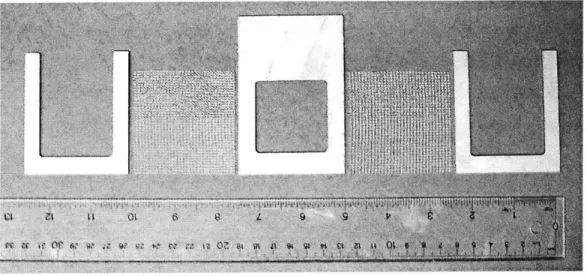
frame include a thicker, 2 mm frame stock and a slightly larger, 1.7 in2 casting window. Stainless steel frame components were custom fabricated by water-jet cutting and their machine drawings are included in the Appendix A. The frame components and mesh
spacer sheets are displayed in Figure 5.
Figure 5: The components of the casting frame for fabrication of 2 mm thick hydrogel slabs.
2.2.4 Hydrogel Casting
This procedure for fabricating chondrocyte-seeded KLD- 12 hydrogels was based on the one used by Kisiday et al. [15, 24]. The appropriate volume of cell solution one hydrogel was centrifuged at 1800 rpm for 10 minutes, during which custom cut pieces of filter paper (Whatman #1) were coated on one side with 0.6% agarose solution and refrigerated until use. During the last minute of centrifuging, the casting frame components were assembled as shown in Figure 6.
Figure 6: The casting frame assembly.
Medium was aspirated from the chondrocyte pellet and the cells were resuspended in a solution of 10% sucrose and 5 mM HEPES buffer, the volume of which was 10% of the final hydrogel volume. The peptide-sucrose solution was drawn into a syringe to 90% of the final hydrogel volume and swiftly injected on top of the cell-sucrose solution. The resulting solution was lightly vortexed and immediately injected into the casting frame window. The entire assembly was then placed in a 1.4x PBS bath to initiate peptide self-assembly. After a minimum time of 1 hour, the frame was removed from the bath and held parallel to the ground while the outer-most U-frame pieces were disassembled. The top mesh piece was slid away and the underlying filter paper was peeled away very slowly to eliminate any spots where the hydrogel may have been stuck to it. Both the filter paper and the mesh were replaced so that the frame could be flipped over and the mesh and paper on the other side could be removed. The window piece was carefully lifted away from the hydrogel and the remaining filter paper supporting the hydrogel was placed in a petri dish and supplied with 23ml of low-serum, 1% ITS-supplemented medium. The filter paper was then removed using sterile forceps and the hydrogel was
placed in an incubator. After 4-5 days in culture, hydrogels slabs were cored with a custom, stainless steel, 12.5 mm diameter punch to produce nine geometrically identical hydrogel disks, which were transferred to 12-well culture plates with 2.5 ml of medium per well. A mature sample is shown in Figure 7.
Figure 7: The top and profile views of a 2 mm thick, chondrocyte-seeded KLD-12 hydrogel at Day 30.
2.3
Results
Casting with the new casting frame produced 2 mm thick, flat slabs of chondrocyte-seeded KLD-12 hydrogels, similar to those previously created with a 1.6 mm frame [15, 24]. After fine-tuning of the frame removal process, fully intact gels could be extracted consistently without sticking to the agarose-coated filter paper. For a
3.6 mg/ml peptide concentration dissolved in a 10% sucrose solution, the minimum time
for peptide self-assembly upon immersion in a PBS bath was determined to be 60 minutes, compared to 25 minutes for a 1.6 mm gel [24]. The day after casting, cell viability in the gel was approximately 80% ± 5% live cells, according to a red/green biofluorescence assay. This result is consistent with that of 1.6 mm hydrogels. Under microscope inspection, chondrocytes also appeared to be evenly distributed throughout the area of the slab.
2.4
Discussion
The successful production of thicker hydrogels was important to the thesis goal of subjecting them to various types of shear deformation, because a gel with a greater
thickness-to-diameter ratio would cause less error in stress response due to frictional sliding between hydrogel and chamber surfaces. It also has positive implications for creation of three-dimensional cell-seeded scaffolds for tissue engineering, which may require unique tissue construct geometries. Constructs with more complex morphology could potentially be made by employing different casting frame geometries or even by stacking two or more slabs on top of each other immediately after casting, allowing biochemical and mechanical integration between them.
Chapter 3
Evaluation of Shear Material Properties
3.1
Introduction
The success of tissue engineered cartilage for use as an in vivo implant depends largely on its ability to withstand the physiological forces present in the joint
environment [15, 24]. Articular cartilage experiences a combination of compression, tension, hydrostatic pressure, pure and simple shear, and fluid-induced shear forces in vivo [29, 35, 64]. These forces not only challenge the tissue's load bearing and joint lubricating functions, but aid its homeostasis as well [57, 64]. If a three-dimensional tissue construct is to fill an articular cartilage defect in vivo, its mechanical properties, such as compressive and shear moduli, must first be assessed in vitro and compared to those of natural cartilage. The compressive moduli of 1.6 mm thick chondrocyte-seeded KLD- 12 hydrogels have previously been measured at time points ranging from 0 to 26 days in culture. By Day 26, the equilibrium modulus was found to be 10% and the dynamic modulus was 5% of the corresponding moduli of native cartilage [15]. For this thesis, the equilibrium and dynamic shear moduli of these constructs have been measured in 5-day intervals, spanning up to 35 days in culture, beginning from the casting date. The shear loading performed here can provide a basis for comparing the mechanical integrity and behavior of the construct material to those corresponding properties of articular cartilage.
3.2
Methods
3.2.1 Specimen Preparation
Chondrocyte-seeded KLD-12 hydrogels were removed from culture at various time points ranging from Day 5-35, where the casting date was Day 0, and placed in Ix PBS solution. A media sample and the wet weight of each specimen were taken for subsequent GAG analysis. The hydrogel thickness was measured and used to calculate the applied shear strain.
3.2.2 Mechanical Testing
The method of shear mechanical testing of the chondrocyte-seeded KLD- 12 hydrogels is similar to that used by Jin et al. for testing of cartilage explants [58]. Mechanical deformation was applied to specimens using an Incudyn apparatus, which can prescribe precise axial and torsional displacements and forces via a computer interface [75]. Samples were placed in a previously used loading chamber (Figure 8), whose base was fixed to the rotational platform of the Incudyn and whose concentrically aligned lid was fastened to an axially actuated post on the machine. Very fine grit sandpaper affixed to both the base and the contact platen of the lid prevented specimen slippage during shear loading.
A hydrogel was placed in the center of the chamber base and the lid was lowered
until it met the sample surface, which was designated as the axial and rotational zero position. The chamber well was then filled with Ix PBS solution and the sample was allowed to equilibrate for 3 minutes, after which the protocol for measuring the
equilibrium shear modulus was initiated. A 15% compressive offset was applied by a 50 ptm/s ramp-and-hold for the duration of 3 minutes. Next, a shear ramp was applied with the same velocity until 1.5% of the sample thickness was reached, and this displacement was held for the rest of 3 minutes. This ramp-and-hold sequence was repeated 3-4 times
consecutively, after which the platen was returned to its rotational zero position, where the hydrogel equilibrated again for 3 minutes.
Following equilibration, the protocol for determining the dynamic shear modulus began. Sinusoidal shear deformation with an amplitude of 0.8% of sample thickness and a frequency of 0.5 Hz was applied for 10 seconds (- 5 cycles) and the platen returned to absolute zero. Data was recorded for all steps at a sampling rate of 256 samples/s by a Dynamic Acquisition Program linked to the Incudyn.
Figure 8: The chamber for applying torsional shear deformation. Patches of fine grit sandpaper on the base and top platen prevent the hydrogel disks from slipping.
3.2.3 Shear Modulus Calculation
The equilibrium modulus was calculated from a plot of the relaxed shear stress versus the applied shear strain. The shear strain at the outer edge of the hydrogel is given
by
OR
= , (1)
h
where 0 is the applied rotational angle, R is the hydrogel radius, and h is the hydrogel thickness. For these experiments, the shear strain was prescribed as a percentage of the sample thickness. The sample radius and thickness were input, so the torsional
displacement to apply could be determined. The shear stress response at the outer edge of the hydrogels was computed from the relation
TR (2)
where T is the measured torque and J is the polar moment of inertia, which for this hydrogel geometry is
J=} IR 4. (3)
Hence, the equilibrium modulus could be calculated by finding the slope of the shear stress after stress-relaxation versus the corresponding shear strain that was applied to produce that stress.
The dynamic shear modulus was determined by tabulating the average top-peak to bottom-peak magnitude for a given sinusoidal stress response, and dividing it by the same average value for the corresponding applied sinusoidal shear strain. Thus the dynamic shear modulus is
3.3
Results
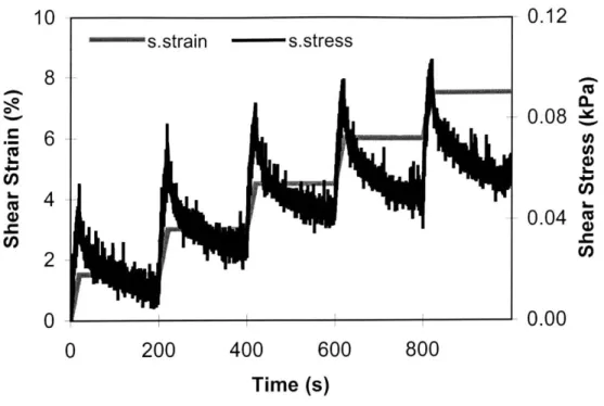
The hydrogel constructs exhibited a stress-relaxation response to the application of ramp shear strains at a rate of 50 [im/sec. The equilibrium modulus was obtained by applying successive shear strain ramps and taking the slope of the relaxation stress values for each strain magnitude. An example of the stress-strain response of a sample at Day
30 is shown in Figure 9. At early time points, the shear stress was not linearly correlated
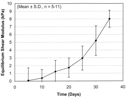
with shear strain and appeared to be random. However, at later time points, some as early as Day 15 and consistently by Day 30, the constructs developed a linear stress-strain relationship, corresponding to an average equilibrium modulus of 5.2±2 kPa. The equilibrium modulus of cartilage at the same ionic concentration has been reported to be ~ 375 kPa [58]. Similar to the relaxed stress, the equilibrium peak stress was linear with strain magnitude at Day 30, but randomly correlated at earlier time points (Figure 10). The hydrogel equilibrium modulus increased over time (Figure 11), with a maximum recorded average of~ 8±1 kPa at Day 35.
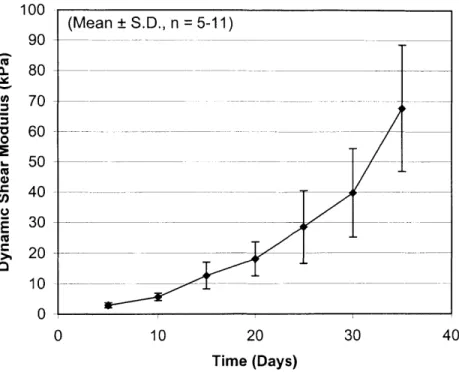
In response to applied dynamic strain, the phase lag between stress and strain demonstrated a viscoelastic quality (Figure 12). As with the equilibrium modulus, the dynamic modulus also increased with time, reaching a maximum average value of
67.7±21 kPa at Day 35 (Figure 13). Comparatively, cartilage explants had a dynamic
modulus of - 1.5 MPa for the same ionic concentration [58]. In the nature of viscoelastic materials, the dynamic stress response was dependent on strain frequency and amplitude. However, only data from the 0.5 Hz frequency and 0.8% amplitude are shown here.
10 -s.strain - s.stress 8 6 4 2-Al U 0 200 400 600 0.12 0.08 CO 0.04 0.00 800 Time (s)
Figure 9: The intrinsic time-dependent stress relaxation response of a 30-day-old construct to successively applied ramp-and-hold shear strains.
0.6 , 2 S0.4 U) Cu0.2 Cn 0.0 0 2 4 6 8 Shear Strain (%)
Figure 10: The peak and equilibrium shear stress of 30-day-old constructs in response to ramp-and-hold shear strain. Both the peak and equilibrium shear stresses show a linear correlation with shear strain, with linear regression R2
values of 0.99 and 0.97, respectively. .. C) U) R2 = 0.9908 A Peak Stress m Eq Stress R 2 =0.9705
a-0 Cn E .0 0* 10 9 8 7 6 5 4 3 2 1 0 0 10 20 30 40 Time (Days)
Figure 11: The average equilibrium shear modulus of constructs over time (n=5-1 1). From Day 5 to Day 35, the modulus increased to 5.2±2 kPa.
-- strain
-stress
H1 2 3
phase lag
Time (s)
Figure 12: A representative shear stress response of constructs to applied sinusoidal shear strain at
0.5 Hz. The ~17 degree difference in phase angle the between stress and strain curves demonstrates
the viscoelastic behavior of the material, with elasticity being dominant over viscous effects.
(Mean ± S.D., n = 5-11) 1.0 0.5 0.0 -0.5 4-CO) W-1.0 0.5 0L 0.0 C-5 -0.5 cf) -1.0 -1.0
100 (Mean S.D., n = 5-11) 90 - --C 80
60
- ---60 5 0 _ - -_ 20 -0 0 0 10 20 30 40 Time (Days)Figure 13: The average dynamic shear modulus of constructs over time (n=5-11). From Day 5 to Day 35, the modulus increased to 67.7±21 kPa.
3.4
Discussion
The equilibrium and dynamic shear properties of chondrocyte-seeded, self-assembling peptide hydrogels over time were determined via the application of torsional, pure shear loading. The material exhibited viscoelastic behavior in response to both equilibrium and dynamic shear deformation. When a shear ramp was applied, the
response was a stress-relaxation curve, attesting to the porous, multi-compositional nature of the material. Stress equilibrium was reached after approximately 2-4 minutes in 30-day-old specimens, compared to 6-10 minutes in explants [58]. A lower density of extracellular matrix molecules in these hydrogels may explain their lower relaxation time constant. As with cartilage explants, the hydrogel stress response to dynamic shear strain was dependent on both frequency and strain amplitude, although only the data for 0.5 Hz
and 0.8% amplitude are presented here. Furthermore, the response to sinusoidal shear
30, similar to a 5-25 degree difference in cartilage [58, 59]. This phase shift value was
consistent among all samples tested at that age. As previously reported, a perfectly elastic material would produce a stress response that is in phase with the applied sinusoidal strain, whereas a perfectly viscous liquid would produce a 90 degree phase shift for the same strain [76]. Therefore, the hydrogel constructs in this study have a combination of elastic and viscous qualities, the former being more dominant and probably resulting from spring-like energy storage in deformed extracellular matrix molecules. The viscous effects manifest energy dissipation, which previous investigators have proposed is a result of frictional interactions between proteoglycan, collagen, and water in cartilage [59]. Since fluid flow can be neglected in this experiment, inter-proteoglycan, inter-collagen, and proteoglycan-collagen interactions are likely to be the sources of viscous dissipation.
As expected, the shear material properties of chondrocyte-seeded KLD- 12 hydrogels were time-dependent, based on measurements taken from Day 5 to Day 35 after casting. Both the equilibrium and dynamic moduli increased over time, reflecting the continuous accumulation of newly synthesized extracellular matrix molecules within the hydrogel scaffolds. This phenomenon may explain why both the peak and
equilibrium shear stress values were randomly correlated with increasing shear strains at early time points, but developed a linear correlation by Day 30, and as early as Day 15 in some specimens. At Day 35, the equilibrium and dynamic stiffnesses were still several orders of magnitude lower than the corresponding material properties of cartilage
explants at the same ionic concentration [58, 77]. This is likely due to lower protein and proteoglycan content and higher water content in the hydrogels at this age. Additionally, the random orientation of collagen fibers in the hydrogels, compared to a more structured orientation in explants may have also contributed to their lower shear stiffness. Hydrogel
shear moduli were also much lower than compressive moduli of the same material, measured by Kisiday et al. [22, 24], because confined compression of the material would result in added stress resistance due to hydrostatic pressure, which is lacking in shear deformation.
Chapter 4
Effect of Dynamic Shear Loading on Chondrocyte
Metabolism
4.1
Introduction
There is much evidence to support the theory that mechanical forces play a crucial role in the development and maintenance of biological tissues. This is certainly the case in articular cartilage, which experiences a wide variety of physiological forces and is a biomechanically and electrochemically complex tissue [64]. Investigators have utilized the knowledge that mechanical forces are coupled to chondrocyte metabolism in attempts to engineer better artificial versions of the tissue. Several kinds of tissue-engineered cartilage have responded positively to dynamic loading [16, 18, 45, 62]. Specifically, Kisiday et al. developed a novel, alternate-day, intermittent, dynamic compression protocol to stimulate proteoglycan synthesis and promote its retention within
chondrocyte-seeded KLD-12 hydrogels [21, 24]. The specific loading pattern that was employed in those studies was derived from dynamic compression schemes that have induced similar results in cartilage explants and chondrocyte-seeded agarose hydrogels
[20, 60, 61, 64]. Similarly, this thesis aimed to reproduce in seeded KLD-12 hydrogels the dynamic shear-induced stimulation of both protein and proteoglycan synthesis that was seen in cartilage explants [35, 57]. Other studies demonstrating that dynamic shear
deformation stimulated biosynthesis in cartilaginous tissue formed in vitro [62, 63] encourage the hypothesis that the same phenomenon could apply to KLD-12 constructs.
The shear loading parameters selected for the experiments here were based on those previously used in both the explant shear and the KLD- 12 hydrogel compression
studies. The chosen loading frequencies, magnitudes, and duty cycles are those that induced the greatest augmentation of biosynthesis in the afore-mentioned studies. A new culture chamber was designed and manufactured to accommodate shear and compressive loading of 12.5 mm diameter hydrogel disks. It is a hybrid of existing chambers for compression and shear applied by an incubator-housed loading apparatus [24, 57], combining the well size of the former with the shear capabilities of the latter.
4.1
Methods
4.1.1 Development of Shear Loading Chamber for Hydrogel Disks
A new polysulfone (PSF) bioreactor for shear loading was designed and machined
(Figure 14). The critical design parameters were large wells to accommodate 12.5 mm diameter hydrogel disks; adjustable-height, porous, polyethylene (HDPE, Porex Corp., Fairburn, GA) platens to adjust for varying sample thickness and to allow nutrient
diffusion during contact; cone-point set screws for securing the platens at a desired height without laterally shifting them; a shear attachment, with which to fix the lid to the
Incudyn for axial movement; an internal geometry such that when the platens were fully raised and the lid was resting on the base, there were no contact stresses on the hydrogels.
Several validation tests were run to ensure that each adjustable platen was evenly contacting the surface of its corresponding hydrogel. Different numbers and distributions of hydrogels were placed in the chamber wells, and the platens were dropped, tightened, and zeroed. In each trial configuration, a compressive ramp was issued, and the
waveform stress response was examined for any inconsistencies that would signify uneven surface contact. The drop-down system was found to be accurate within ± 25 [m
The polysulfone chamber base, lid, and screw components could be sterilized by autoclaving. However, autoclaving of the HDPE platens caused them to warp slightly and loosen from their PSF holders. Therefore, the platens and their holders were ethanol sterilized and thoroughly rinsed with PBS prior to specimen contact.
Figure 14: A new shear polysulfone chamber for shear loading of the constructs. Notable features include adjustable-height porous platens, large well size, and top shear-axel attachment.
4.1.2 Shear Loading
Chondrocyte-seeded KLD-12 hydrogels were transferred to individual wells of the shear loading chamber, and the lid was placed on top, such that there was no contact
between the hydrogels and the loading platens. Low-serum medium (see Chapter 2) was supplied to each occupied well via syringe injection through 0.625 in diameter feedholes in the lid. To preserve sterility within the chamber, two layers of gauze were lightly soaked with ethanol and wrapped around the circumference of the chamber, covering the gap between the base and the lid, and gauze pieces were stuffed into the feedholes. The adjustable platens were then released to lightly rest on the hydrogel surfaces, keeping the hydrogels centered in the wells while the chamber was positioned in the Incudyn (Figure
15). The axially actuated Incudyn post was lowered into the shear lid attachment and
fixed to it with set screws. An axial and rotational zero position was established by raising the lid approximately 800 tm, at which each platen, still resting on its
corresponding hydrogel surface, was tightened in place. Free-swell control disks were present both in the shear chamber and in a 12-well culture plate, which was placed in the incubator, adjacent to and at the same height as the Incudyn platform.
Beginning with the platens at absolute zero, a 5 or 10% compressive offset was applied, followed by the dynamic shear protocol. Several different shear sequences were tried and their parameters are listed in Table 1, including the amplitude of sinusoidal shear displacement, the dynamic shear frequency, the duty cycle of loading, the hydrogel age at the start of loading, and the types of free-swell controls used. During a rest period in the duty cycle, the platens were raised to approximately 800 .tm above zero, so that the samples were in free-swelling. For the necessary protocols, culture medium was changed every other day. At the start of the final 24 hours of the protocol, radiolabel medium
containing 10 tCi/ml of 3 5S-sulfate and 20 4Ci/ml of 3H-proline was fed to the
specimens. At the end of this period, all samples were removed for biochemical analysis.
Table 1. Dynamic shear loading protocols.
Protocol Amt. (%) Frea. (Hz) Duty Cycle (hours:minutes) Aee (days) Free-swell Control
A 2 0.1 0:30 on. 23:30 off 24:00 rest 14 chamher & 12-well
B 2 0.1 4 x (0:15 on. 5:45 off). 24:00 rest 20 chamher
C 2_5 0.3 4 x (0:45 on. 5:15 offt 24:00 rest 27. 24 chamber & 12-well D 2.5 0.3 2 x (0:45 on. 5:15 off 24:00 rest) 34 chamher & 12-well
Figure 15: The incubator-housed loading apparatus for the precise application of compression and shear. The shear chamber containing tissue constructs is wrapped to preserve sterility and mounted on the Incudyn.
4.1.3 Biochemical Analysis
After various loading protocols, the hydrogel specimens were washed four times in a radiolabel rinse, consisting of Ix PBS and 1 mM unlabeled proline and sulfate to remove all unincorporated radiolabel, after which disk wet weights were recorded. Six to seven 3 mm diameter plugs were then extracted from each 12.5 mm diameter hydrogel
disk, wet weight measured, and digested overnight in 1 ml of proteinase K (Roche) and Tris-HCl solution at 60 C. Radiolabel incorporation levels of each sample digest were analyzed using a scintillation counter and normalized to plug wet weight. Culture medium from each hydrogel was subjected to a colorimetric DMMB dye assay to assess the amount of GAG loss from the sample. These readings were normalized to the wet weights of corresponding hydrogel disks.
4.2
Results
Radiolabel incorporation levels of chondrocyte-seeded KLD-12 hydrogels that were subjected to dynamic shear deformation were compared to those of free-swell controls. In all cases, the biosynthesis rates of chamber specimens, both loaded and free-swell, were significantly lower than those of controls in 12-well plates. This effect was present regardless of the chosen compressive offset, shear amplitude, frequency, and
loading time. In sheared samples, incorporation of 3H-proline and 3 5S-sulfate
respectively ranged from 41-68% and 34-79% of the corresponding levels in 12-well free-swell controls. Representative results from several of these experiments are shown in Figure 16 and Figure 17. Comparison between loaded and chamber free-swell
constructs revealed very similar biosynthetic levels, such that neither group was consistently higher or lower than the other.
The amount of GAG lost from sheared hydrogels into their culture medium was compared to that of chamber free-swell and 12-well free-swell samples. In all instances,
GAG levels in the medium of sheared samples were 1-3.5 times those of 12-well
controls. In the medium of shear chamber free-swell samples, GAG levels ranged from 0.7-5 times those in 12-well control medium.
0.040 ** = compared to Sh FS and FS (p<0.001) 0.035 1-0.030 E 0.025 -E C r 0.020 0 0.015 Ij 0.010 0.005 0.000 -** I-Proline ** T oSh MSh FS 0 FS Sulfate
Figure 16: The 3H-proline and 3 5S-sulfate incorporation in dynamically sheared (Sh), shear chamber
free-swell (Sh FS), and 12-well plate free-swell (FS) constructs. Incorporation in sheared samples was significantly lower (p<0.001) than in both other groups.
0.04 0.035 + 0.03 E 0.025 E C c 0.02 o 0.015 0 . U .E 0.01 0.005 -0 * = compared to Sh FS (p<0.05) * f-Proline ESh FS O Sh o FS Sulfate
Figure 17: The 3H-proline and 3 5S-sulfate incorporation in dynamically sheared (Sh), shear chamber free-swell (Sh FS), and 12-well plate free-swell (FS) constructs. Compared to chamber free-swell, incorporation in the sheared disks was significantly higher (p<0.05), and both of those groups had significantly lower (p<0.001) incorporation than the 12-well free-swell controls.
_T_
4.3
Discussion
Physical forces are known to have a significant effect on the metabolism of chondrocytes in many different environments, whether in vivo tissue, cartilage explants, monolayer cultures, or tissue engineered constructs [14, 16-20, 24, 35, 57, 62, 63]. While these forces can certainly have a destructive influence, certain modes of dynamic
mechanical loading have been shown to enhance biosynthesis of ECM molecules by chondrocytes. Jin et al. demonstrated that dynamic shear loading could stimulate protein and proteoglycan production in cartilage explants [35, 57], while Waldman et al. reported the same effect in cartilaginous tissue formed by in vitro chondrocyte cultures [62, 63].
To investigate whether the same biosynthetic enhancement would apply to chondrocyte-seeded KLD-12 hydrogels, they were subjected to various dynamic shear protocols and the radiolabel incorporation of newly synthesized protein and proteoglycan in the constructs was analyzed. In contrast to previous studies, sheared specimens showed a dramatic decrease in both protein and proteoglycan synthesis, compared to controls in 12-well culture plates. Both the sheared constructs and the 12-well controls exhibited slightly higher proteoglycan incorporation over protein incorporation, although occasionally in shear samples, neither matrix component had a significantly higher incorporation rate than the other.
The shear loading parameters applied to the hydrogel constructs were chosen based on those used in previous shear studies, as well as those used in studies of dynamic compression of seeded KLD-12 hydrogels [24]. They combined low frequencies, low amplitudes, and intermittent loading patterns, which prior research identified as anabolic stimuli. Initially, the suppressed biosynthesis seen in shear constructs was thought to be due to adverse loading parameters. However, the same occurrence in free-swelling constructs in the loading chamber suggested that the biosynthetic repression might have been an artifact of the chamber itself, instead of a side effect of loading. Observation of increased GAG loss to the medium in both loaded and unloaded chamber samples, compared to 12-well controls, supported this new hypothesis and prompted a more thorough investigation of the shear chamber as a suitable environment for hydrogel culture. The details of this spin-off chamber study are described in Chapter 5.