HAL Id: in2p3-00102985
http://hal.in2p3.fr/in2p3-00102985
Submitted on 3 Oct 2006
HAL is a multi-disciplinary open access
archive for the deposit and dissemination of
sci-entific research documents, whether they are
pub-lished or not. The documents may come from
teaching and research institutions in France or
abroad, or from public or private research centers.
L’archive ouverte pluridisciplinaire HAL, est
destinée au dépôt et à la diffusion de documents
scientifiques de niveau recherche, publiés ou non,
émanant des établissements d’enseignement et de
recherche français ou étrangers, des laboratoires
publics ou privés.
particle-in-cell code
J.T. Donohue, J. Gardelle
To cite this version:
J.T. Donohue, J. Gardelle. Simulation of Smith-Purcell Terahertz radiation using a particle-in-cell
code. 27th International Free Electron Laser Conference, Aug 2005, Stanford, United States.
pp.262-265, 2005. �in2p3-00102985�
SIMULATION OF SMITH-PURCELL TERAHERTZ RADIATION USING A
PARTICLE-IN-CELL CODE
J.T. Donohue, Centre d'Etudes Nucléaires de Bordeaux-Gradignan, BP 120,
33175 Gradignan, France
J. Gardelle, CEA CESTA, BP 2, F-33114 Le Barp, France
Abstract
A simulation of the generation of Smith-Purcell (S-P) radiation at terahertz frequencies is performed using the two-dimensional particle-in-cell code MAGIC. The simulation supposes that a thin (but infinitely wide), mono-energetic electron beam passes over a diffraction grating. We simulate two configurations, one similar to the Dartmouth S-P FEL, with a low-energy continuous beam (we use an axial magnetic field to constrain the electrons to essentially one-dimensional motion). The other is similar to the recent MIT experiment that uses a pre-bunched 15 MeV beam.
INTRODUCTION
In a recent publication [1] we reported on a simulation of coherent Smith-Purcell radiation using a two-dimensional particle-in-cell code, MAGIC. The grating period and the beam energy were chosen such that the radiation produced was in the microwave region, with frequency of order 10 GHz. We remind the reader of the S-P relation, λ=L
(
1/β−cosφ)
/n, where λ is the wavelength, L the grating period, β the relative velocity (in a plane parallel to the grating and perpendicular to the direction of the grooves), φ the angle of emission (with respect to the beam direction), and the integer n denotes the order. Our aim was to verify the analytical model proposed by Andrews and Brau [2] and subsequently extended by Andrews, Boulware, Brau and Jarvis [3] to explain coherent Smith-Purcell radiation. Since our previous experience with the code had been in the microwave domain, we preferred to work there. Our results do indeed support the viewpoint of Brau and co-workers, that the mechanism for coherent radiation is the bunching of the initially continuous beam by an evanescent wave that is significant only in the vicinity of the grating. The frequency of this wave is always less than the minimum allowed S-P frequency. The process is unstable in the sense that the wave bunches the beam, the beam drives the wave and growth occurs, both in time and along the grating. Our simulation found that this is what happens. In particular, the frequency and axial wave number (in the first Brillouin zone) of the simulated grating wave were very close to what the model predicts. However, it also revealed two major effects that had not been anticipated. Since our simulated grating has a finite length, when the evanescent wave reaches the end, part of its energy is emitted as free radiation of the same frequency, and part of it is reflected back in the opposite direction. The surprise is that the reflected wave has twodistinct wave numbers, the original one (which we call
k+), and a second, (k-) which is the other solution of the
grating dispersion relation for the same frequency. The same thing happens at the upstream end of the grating, and the net result is that four distinct evanescent waves are generated, with wave numbers k+, -k+, k-, and -k-.
Although only the wave with k+ is resonant with the
beam, the other waves have comparable and even greater amplitudes in the neighborhood of the grating. The situation is thus somewhat more complicated than that imagined by Brau and co-workers. As a consequence, the radiation emitted at the ends is copious, and its frequency is always below the minimum S-P frequency for the grating period and beam velocity. To the best of our knowledge, no observation of this radiation has been reported by the various groups studying S-P radiation experimentally. However, the two-dimensional nature of our simulation requires a beam of infinite width in the direction of the grooves. In practice, we imagine that beam at least several wavelengths wide would be necessary, but the existing experiments typically use narrow round beams. Thus confirmation of the results of our simulation and the validity of the Andrews and Brau model will need dedicated experiments with wide beams.
The main interest in S-P FELs is the possibility they offer of being compact, powerful and tunable sources of THz radiation. An example is the on going Dartmouth College experiment [4], initiated by Walsh many years ago, and often reported on in this series of conferences. This experiment typically uses optical gratings of period 0.17 mm, and beam energies in the range 30-50 keV. To reach THz frequencies only the lowest S-P orders are needed. Quite recently a new direction was opened by a group at MIT [5] using the beam from a linac operating at 17.14 GHz, that delivers pulses of duration 1 ps. The beam energy was 15 MeV, and the grating period was 1 cm. Here the THz domain requires high orders near 90°. An important issue in both of these experiments is coherence. According to ref. 3, there are two distinct concepts involved, intra-bunch and inter-bunch coherence. The former obtains whenever the physical size of an electron bunch is small compared to the wavelength of the radiation observed. Then the fields created by each electron in the bunch add up, and the total power radiated will be proportional to the square of the number of electrons per bunch. This occurs for all wavelengths such that the ratio of bunch size to wavelength is <<1. Inter-bunch coherence requires, in addition to the bunch-size criterion, that the contributions of successive bunches add coherently at the observation
point. This occurs whenever the frequency of the bunches (inverse of the time interval between two successive bunches) is equal to the frequency of the S-P radiation. This is never true for the fundamental, but since bunching is non-linear, higher harmonics may also appear in the current. When this happens coherent S-P radiation may occur at angles φ and order n such that
(
β φ)
π
ω =2 cn/L1/ −cos
ev
m . In this expression ωev is the frequency of the evanescent wave, and m is an integer.
In the Dartmouth experiments, with an initially continuous beam, the intersection of the beam line and the grating dispersion relation determines the operating point, i.e., the frequency of the evanescent wave. In contrast, in the MIT experiment, the beam is already bunched when it reaches the grating, and the Andrews-Brau operating point is irrelevant. Since the pulses are periodic in time, inter-bunch coherent S-P radiation occurs whenever the angle and order are such that the frequency is an integer multiple of the repetition frequency, namely 17.14 GHz.
DETAILS OF THE SIMULATIONS
The simulations are performed using the commercially available code MAGIC. It is a 2D/3D electromagnetic PIC code, i.e., a finite-difference, time-domain code for simulating plasma physics processes. Beginning from a specified initial state, the code simulates a physical process as it evolves in time. The full set of Maxwell's time-dependent equations is solved to obtain electromagnetic fields. Similarly, the complete Lorentz force equation is solved to obtain relativistic particle trajectories, and the continuity equation is solved to provide current and charge densities for Maxwell's equations. Our version of the code is two-dimensional; it assumes that all fields and currents are independent of the
z-co-ordinate. However, the motion of electrons is
calculated in three dimensions.
L
MIT
Dartmouth
A H L x y zφ
AbsorbersFigure 1: Simulation geometry.
In Figure 1, we display the geometry we have chosen for our 2D Cartesian simulation, where the electron beam propagates in the x-direction. The set-up includes a perfectly conducting grating in the center at the bottom, a small cathode, which emits beam, and a vacuum box in which radiation propagates. The boundary consists of absorber, shown crosshatched, which prevents most of the radiation reaching the walls to reflect back into the box.
We have verified that this feature of MAGIC greatly suppresses reflection.
The choice of observable quantities is quite rich: electric and magnetic field components as a function of time, or as functions of space at fixed time. The electron phase space, currents and the Poynting vector may also be displayed. Our uniform density electron beam is thin in the y-direction and infinite in the z-direction. For the Dartmouth simulation the beam leaves the cathode steadily, while for the MIT simulation a square-wave pulse of current of duration 1 ps is emitted at a frequency of 17.14 GHz. The MIT grating is of the échelette type, while that of Dartmouth is laminar. We summarize the simulation parameters in Table 1.
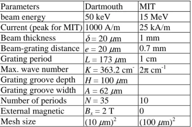
Table 1: Simulation Parameters
Parameters Dartmouth MIT beam energy 50 keV 15 MeV
Current (peak for MIT) 1000 A/m 25 kA/m Beam thickness δ= 20 μm 1 mm Beam-grating distance e = 20 μm 0.7 mm Grating period L = 173 μm 1 cm Max. wave number K =363.2 cm- 2π cm-1 Grating groove depth H = 100 μm
Grating groove width A = 62 μm Number of periods N = 35 10 External magnetic Bx = 2 T 0 Mesh size (10μm)2 (100 μm)2
RESULTS OF THE DARTMOUTH
SIMULATION
In Figure 2 is shown the dispersion relation for the grating in the Dartmouth simulation, along with the light line and the beam line for 50 keV electrons. The operating point P is shown, f = 473 GHz, k+/2π = 3824 m
-1
.together with the other solution of the same frequency P′ , with k-/2π =
1956 m-1
. At P, the group velocity is negative, which means that electromagnetic energy flows upstream, as in the Backward Wave Oscillator.
Figure 2: Dispersion relation for Dartmouth Grating. In Figure 3 a contour map of the magnetic field components Bz and By in the x-y plane at time t = 0.9 ns is
Figure 3: Contour maps of Bz and By.
In fact, these are composite maps, each of 2-mm width in y and joined together afterwards, to maintain color contrast. Although in the ideal case there is only a z-component of the magnetic field, the small transverse motion of the electrons gives rise to very small x and y components as well. While the contour map for Bz is
complex, dominated mainly by the evanescent wave (of wavelength 0.635 mm, visible on the left), the map of By
indicates radiation of half that wavelength emerging at a well-defined angle of approximately 55°. Guided by this one can discern the same thing in the Bz map, although it
is masked by the presence of the evanescent wave. This is the second harmonic of the evanescent wave, which is emitted coherently at 54°.
Figure 4: Bz(t) at φ = 50°, and its FFT.
In Figure 4 we show Bz(t) at angle 50°, along with Finite Fourier Transform (FFT) of the signal. The time signal shows rapid growth after 0.5 ns. The frequency of the evanescent wave is indicated, and one sees that the second harmonic is the dominant frequency. Tiny amounts of third and fourth harmonics are also visible. Note that the fourth harmonic in second order should be coherent at the same angle as the second harmonic in first order.
In Figure 5 we show a snapshot of the beam just above the grating, along with its distribution in T-x phase space, where T denotes the kinetic energy. Strong bunching is apparent in both. By counting oscillations we estimate approximately 0.25 mm for the wavelength, quite consistent with the value expected from the dispersion relation. We also note that the mean energy loss is 1-2 keV or 2 to 4 % of the beam energy.
Figure 5. Section of beam above grating (upper), and T-x phase-space distribution.
To illustrate the presence of the evanescent wave corresponding to the point P′ in Figure 2, we show in Figure 6(a) , the quantity Bz vs. x at fixed time (0.9 ns) and at a y position just above the grating. The corresponding FFT is shown in Figure 6(b).
Figure 6: (a) Bz(x), (b) FFT, (c) I(x), (d) FFT. For comparison, the quantity I(x) (I has dimension of Amp/linear meter) is displayed in Figure 6(c), with its FFT in Figure 6(d). It is clear that the behavior of these two quantities is quite different. The modulation of the current increases with increasing x, while that of the magnetic field does the opposite. The visible period of the oscillations in Bz is about 0.5 mm, quite different from that of the current, but entirely consistent with k- in the
Andrews and Brau dispersion relation. The FFTs confirm this picture, and illustrate the difference between the two.
For the magnetic field, Floquet theory implies
( )
x e u( )
xB ikx
z = , where u(x) is periodic of period L, and
the wave number is given by the dispersion relation. The Fourier spectrum (with our convention) should show peaks at
k
/
2
π
+
N
/
L
, where N denotes an integer (1/L= 5780). Since the dispersion relation provides two values for k, we get two series of peaks. In contrast, the beam is only resonant with the greater k value, and the presence of multiples of this wavenumber is due to the non-linear nature of bunching.MIT SIMULATION
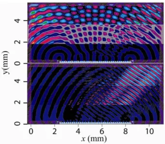
In Figure 7 we show two contour plots of Bz in the x-y plane at fixed time, 1.7 ns.
Figure 7: Bz contour maps without and with grating. In the upper figure there is no grating, but rather a 10-cm long flat plane, while the lower has an échelette grating. The upper map is not S-P radiation. Indeed, in the limit of zero beam thickness and neglecting minor effects of the cathode and beam stop, we can write the quantity Bz
(
x,y,t)
in closed form using standardelectrodynamics. The lower map obviously bears an overall resemblance, but has a much richer spatial structure, since true S-P radiation occurs. In order to quantify the difference, we show in Figure 8 Bz(t) at
φ = 48° for both cases, along with their FFTs.
Figure 8: Bz(t) and FFT without and with grating. The distance from the grating center is 10 cm. At 48°, the lowest S-P frequency is 90 GHz; the second order is 180. The sixth and twelfth harmonics, at 102 and 204 GHz, would be S-P coherent at 45°. This may account for their strong presence in the FFT.
CONCLUSIONS
We have presented results concerning simulations of coherent Smith-Purcell Radiation, using a 2-D PIC code. Both of the experiments we attempt to simulate use narrow round beams, and it is not prudent to claim that all of the phenomena we predict should be seen experimentally. Given this caveat, we find that our Dartmouth set-up simulation lends support to the model of Brau and co-workers, while the simulation of the short-pulse MIT experiment suggests that an interpretation only in terms of coherent S-P radiation may oversimplify the true situation.
REFERENCES
[1] J. T. Donohue and J. Gardelle, Phys. Rev. ST Accel. Beams 8, 060702 (2005).
[2] H. L. Andrews and C. A. Brau, Phys. Rev. ST Accel. Beams 7, 070701 (2004).
[3] H. L. Andrews, C. H. Boulware, C. A. Brau and J. D. Jarvis, in Proceedings of the 2004 FEL Conference,
Trieste, Italy, p. 278 (http://www.JACoW.org).
[4] A Bakhtyari, J. E. Walsh, and J. H. Brownell, Phys. Rev. Lett. E 65, 066503 (2002).
[5] S. E. Korbly, A. S. Kesar, J. R. Sirigiri, and R. J. Temkin, Phys. Rev. Lett. 94, 054803 (2005).