Chemically Enhanced Primary Treatment of Wastewater in Honduran
Imhoff Tanks
by Anne M. Mikelonis B.S. Civil Engineering Northwestern University, 2007SUBMITTED TO THE DEPARTMENT OF CIVIL AND ENVIRONMENTAL ENGINEERING IN PARTIAL FULFILLMENT OF THE REQUIREMENTS FOR THE
DEGREE OF
MASTERS OF ENGINEERING IN CIVIL AND ENVIRONMENTAL ENGINEERING AT THE
MASSACHUSETTS INSTITUTE OF TECHNOLOGY JUNE 2008
© 2008 Massachusetts Institute of Technology. All Rights Reserved.
Signature of Author...………. Department of Civil and Environmental Engineering May 9, 2008 Certified by.………...………
E. Eric Adams Senior Research Engineer and Lecturer of Civil and Environmental Engineering Thesis Supervisor
Accepted by……….……….. Daniele Veneziano Chairman, Departmental Committee for Graduate Students
Chemically Enhanced Primary Treatment of Wastewater in Honduran
Imhoff Tanks
by
Anne M. Mikelonis
Submitted to the Department of Civil and Environmental Engineering On May 9, 2008 in Partial Fulfillment of the
Requirements for the Degree of Master of Engineering in Civil and Environmental Engineering
ABSTRACT
Imhoff tanks represent approximately 40% of the wastewater treatment infrastructure in Honduras. This thesis evaluates the usage of solid aluminum sulfate as a means to achieving national effluent regulations in Imhoff tanks in the municipality of Las Vegas, Santa Barbara. The report contains a brief background on both Imhoff tanks and chemically enhanced primary treatment and a discussion of the governing technical considerations. The residents of Las Vegas produce a very high amount of relatively dilute domestic wastewater (approximately 1,000 liters/person/day). Bench scale testing and pilot testing during January 2008 in the Las Vegas Imhoff tanks found that a dosage of approximately 150 mg/l alum (17% Al2O3) was necessary to treat Las Vegas’ domestic wastewater. However, solution preparation and chemical injection were found to be difficult to achieve under current conditions and the cost of alum in this quantity is prohibitively expensive. The final recommendations to the municipality of Las Vegas include encouragement to conserve water and a comprehensive plan to better maintain the Imhoff tanks in order to achieve higher levels of treatment.
This thesis also documents the author’s efforts to ascertain the status of Imhoff tanks in the rest of Honduras in terms of their size, design, and maintenance. During January 2008 three other Imhoff tanks in the department of Santa Barbara and one in the department of La Páz were visited and all were found to be in varied states of disrepair. However, several hold the potential to be rehabilitated after the removal of sludge.
Thesis Supervisor: E. Eric Adams
Acknowledgements
This thesis is the product of the efforts of many people. First and foremost I would like to thank my teammates. The support and guidance from Matt Hodge, Ari Herrera, Dr. Eric Adams, and Dr. Des Lawler were critical to my work. Matt was a great compatriot throughout the year and a fearless driver during our time in Honduras. Ari was extremely instrumental in the organization and execution of the project and brought a contagious positive energy to every aspect of the project in which he was involved. I would like to thank Eric for meticulously reviewing countless drafts of calculations and presentations throughout the year. He was always available for moral support, sound technical advice, and was a real pleasure to have as my advisor. Des adopted our team despite being at UT-Austin and his availability and advice was always very much appreciated.
The members of the municipal staff of Las Vegas were a pleasure to work with during our January fieldwork. This project could not have happened without the blessing and assistance of Mayor Carlos Fuentes and the Vice-Mayor Professor Isaias Castellano nor the support from city engineers Marcos Godoy, and Alexis Rodriguez. Evers Garcia was an excellent guide to the city of Las Vegas and instrumental in completing much of our research. Further, I owe my gratitude to the team of plumbers in Las Vegas including Santos and Theodoro for helping me to construct baffles, flow gates, and run the CEPT pilot test. I would also like to thank Diana Betancourt of Water for People, Manuel Lopez of Aguas de San Pedro, and Jocobo Nuñez of Agua Para el Pueblo for their insights into the sanitation sector in Honduras and assistance in gathering information.
I also owe a huge thank you to Professor Monroe Weber-Shirk of Cornell University and Fred Stottlemyer of the International Rural Water Association for inviting me to work in Honduras during the summer of 2005. Their support throughout the years has instilled in me a great love for Honduras and for the field of environmental engineering.
My time at MIT has been extremely enjoyable, but this would not have been the case without the friendship and enthusiasm of my fellow classmates in the MEng program - - Thank you for creating such a warm and friendly atmosphere! Further I want to thank Professors Pete Shanahan and Susan Murcott for their feedback on my project and stimulating courses. Also thanks to Gayle Sherman and Kris Kipp for all of their office assistance. Additionally, I truly appreciate the sponsorship of the National Science Foundation for allowing me to learn so much without a financial burden.
Last, but certainly not least, I must thank my family. Words cannot express the gratitude I feel towards my parents, sister Greta, and brother Tony for their tremendous love and support. My grandparents traveled extensively during the 1980s and 90s. For as long as I can remember I have been regaled with their stories from abroad. They instilled in me a great sense of international curiosity and respect and taught me never to leave home without a big roll of duct tape. Throughout college my grandma was an avid reader of my travel blogs, a dedicated letter writer and one of my biggest cheerleaders and best friends. Last week my grandparents took their last trip. My grandpa passed away April 27th and grandma May 1st. The stories and example my grandparents set have greatly influenced me. Thank you Grandma Gretchen and Grandpa Fred!
Table of Contents
1 INTRODUCTION ... 8
1.1 Project Background ...8
1.2 Report Objective...9
2 OVERVIEW OF SANITATION IN HONDURAS ... 10
2.1 Country Background...10
2.2 Coverage ...10
2.3 Institutions...11
2.4 Funding ...12
2.5 Existing Systems ...13
2.6 National Wastewater Regulations ...15
3 OVERVIEW OF IMHOFF TANKS... 16
3.1 Background ...16 3.2 Mechanics ...16 3.3 Design Criteria ...18 3.4 Advantages ...18 4 OVERVIEW OF CEPT ... 19 4.1 Introduction ...19 4.2 History...19 4.3 Coagulation/Flocculation ...21 4.4 Chemicals...22 4.5 Sedimentation...23 5 LAS VEGAS ... 24 5.1 Geography...24 5.2 Population ...25
5.3 Water and Wastewater Treatment ...25
5.4 Imhoff Tanks ...26 5.4.1 Service Area ...27 5.4.2 Dimensions ...28 5.4.3 Flows ...30 5.4.4 Loads...32 5.4.5 Maintenance...34
5.4.6 Receiving Stream/Water Quality Issues...37
6 CEPT AT LAS VEGAS... 38
6.1 Chemicals...38
6.2 Bench Scale Testing ...39
6.2.1 Field Conditions...39
6.2.2 Jar Testing Methods ...39
6.2.3 Jar Testing Results ...42
6.2.4 Discussion...44
6.3 Pilot Test ...47
6.3.1 Procedure...47
6.3.3 Results ...48
6.3.4 Discussion...50
6.4 Sludge Production...51
6.5 Economics ...52
6.6 Conclusions ...52
7 STATUS OF IMHOFF TANKS... 53
7.1 Marcala, La Páz ...53
7.2 Barrio El Llano del Conejo, Santa Barbara...55
7.3 Barrio Galeras, Santa Barbara ...55
7.4 Gualala, Santa Barbara...56
7.5 Site Investigation Protocol ...58
7.6 Conclusions ...59
8 CONCLUSIONS... 60
9 REFERENCES ... 61
APPENDIX A: PROJECT TIMELINE ... 64
APPENDIX B: CALCULATIONS FOR FIELD MIXING CONDITIONS ... 67
APPENDIX C: JAR TESTING RAW DATA ... 69
APPENDIX D: BRAZIL ALUM JAR TESTING RESULTS ... 74
Table of Figures
Figure 2.1 Map of Honduras...10
Figure 3.1 Imhoff Tank Schematic ...16
Figure 5.1 Las Vegas...24
Figure 5.2 Las Vegas Urban Neighborhoods ...25
Figure 5.3 Las Vegas Imhoff Tanks...26
Figure 5.4 Top View ...26
Figure 5.5 Inside View of Sedimentation Chamber...26
Figure 5.6 Sludge Valves ...26
Figure 5.7 Imhoff Tank Service Area ...27
Figure 5.8 Plan View Las Vegas Imhoff Tanks (from Herrera, 2006) ...28
Figure 5.9 Dimensions of One Las Vegas Imhoff Tank ...29
Figure 5.10 Dimensions of Upstream Channel (not to scale)...29
Figure 5.11 Las Vegas 2003 Flows (from Herrera, 2006) ...30
Figure 5.12 Coffee Beans in Scum Chamber ...32
Figure 5.13 Scouring...34
Figure 5.14 Wooden + Sand Bag Flow Gate...35
Figure 5.15 Inlet Baffles...35
Figure 5.16 Inner Scum Chambers ...36
Figure 5.17 Scum Scraper ...36
Figure 5.18 COD in Raices Creek ...37
Figure 5.19 Raices Creek ...37
Figure 6.1 Honduras Alum ...39
Figure 6.2 Phipps and Bird Jar Testing Apparatus ...40
Figure 6.3 G-Curve ...41
Figure 6.4 Average % Removal of Turbidity by Honduras Alum...42
Figure 6.5 Average % Removal of Suspended Solids by Honduras Alum...43
Figure 6.6 % Removal of COD by Honduras Alum...43
Figure 6.7 Dosage Averaged Turbidity Results ...44
Figure 6.8 Dosage Averaged Suspended Solids Results...44
Figure 6.9 Aluminum Sulfate – pH Stability Limit (Sung, 2008) ...45
Figure 6.10 Effect of Influent Conditions on Removal...46
Figure 6.11 Pilot Test Feed System ...47
Figure 6.12 Alum Paste...47
Figure 6.13 CEPT “Soapy Bubbles”...48
Figure 6.14 CEPT “Milky Flow”...48
Figure 6.15 Pilot Test TSS Influent and Effluent Levels ...49
Figure 6.16 Pilot Test COD Influent and Effluent Levels ...49
Figure 6.17 CEPT Sludge Production...51
Figure 7.1 Marcala Imhoff Tank...54
Figure 7.2 Marcala Inlet ...54
Figure 7.4 Incomplete Sedimentation Chamber in Barrio El Llano del Conejo ...55
Figure 7.5 Barrio Galeras Imhoff tank ...56
Figure 7.6 Barrio Galeras V- Notch Weir ...56
Figure 7.7 Barrio Galeras Bypass ...56
Figure 7.8 Gualala Imhoff Tank ...57
Figure 7.9 Gualala Broken Wall ...57
Figure 7.10 Department Distribution of Imhoff Tanks ...59
Table of Tables
Table 2.1 Honduras Wastewater Treatment Systems ...14Table 2.2 Honduras Wastewater Regulations...15
Table 3.1 Design Criteria for Unheated Imhoff Tanks (from Herrera, 2006)...18
Table 5.1 January 2008 Flows (from Hodge, 2008) ...31
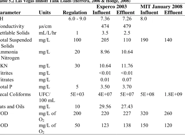
Table 5.2 Las Vegas Imhoff Tank Loads (from Herrera, 2006 & Hodge, 2008)...33
Table 6.1 Field Mixing Conditions ...39
Table 6.2 Solubility of Alum...47
Table 6.3 Pilot Test Collected Data ...48
Table 6.4 COD and TSS Average % Removal for Pilot Test...50
1 INTRODUCTION
1.1 Project Background
An Imhoff tank is a structure designed to provide primary wastewater treatment. It is a sedimentation tank with a steeply sloped floor resting above a sludge digester. During the 1930’s, Imhoff tanks represented 50% of all wastewater treatment facilities in the United States (Herrera, 2006). While the majority of Imhoff tanks within the U.S. have since been abandoned or modified to adapt to changing treatment objectives and regulations, within Honduras they continue to represent a significant portion of wastewater treatment infrastructure.
During the 2005-2006 school year, students from the MIT Master of Engineering (MEng) Program in Environmental Engineering studied the water quality of Lake Yojoa, the largest freshwater lake in Honduras. During their study, students Tia Trate and Mira Chokshi recognized that the bordering municipality of Las Vegas was a major polluter of Lake Yojoa. Two Imhoff tanks in parallel receive wastewater from the urban center of Las Vegas before discharging into a creek that empties into the lake.
Lack of proper maintenance and community knowledge has led to a widespread state of disrepair in Honduran Imhoff tanks both in Las Vegas and elsewhere. Recognition of this situation led Aridaí Herrera, a Honduran native, to focus his graduate work at the University of Texas-Austin on the rehabilitation of Imhoff tanks. Herrera tailored his research to the municipality of Las Vegas and at the end of 2006 produced a detailed rehabilitation and maintenance plan for the Imhoff tanks. In his role as consultant to Las Vegas, he relayed a request to MIT for assistance in considering options for a total system expansion. As part of the appeal, he requested documentation of baseline flows and loads as well as treatment options for incorporating the remaining unconnected population of Las Vegas into the system.
The municipality of Las Vegas has both term and long-term treatment goals. In the short-term, the city aims to provide treatment for the existing load on the Imhoff tanks. In the long-term, the municipality’s goals include both full treatment of wastewater for the currently connected homes and enterprises and service area expansions so that all of the wastewater generated in the municipality is being treated. Realistically there are long lead times associated with obtaining funding for the construction of new infrastructure. Therefore, Herrera was interested in the effectiveness of chemically enhanced primary treatment (CEPT) within Imhoff tanks as an interim solution towards meeting national effluent regulations. Additionally, he was curious whether CEPT could accommodate sufficiently large surface overflow rates so that the Imhoff tanks might also be able to accommodate modest service area expansions.
Matthew Hodge and Anne Mikelonis, both MIT Environmental Engineering MEng students, spent the 2007-2008 school year responding to Herrera’s appeals. January 2008 found them in Honduras meeting with stakeholders and performing lab and fieldwork. Hodge’s work focused on documenting flows and loads in Las Vegas and evaluating various options for total system expansion and sludge maintenance. Mikelonis’ work focused on evaluating the applicability of CEPT within Imhoff tanks through bench scale and pilot testing. A detailed timeline of the MIT
involvement with Lake Yojoa, Honduras and the onsite activities of the team during January are documented in Appendix A: Project Timeline.
1.2 Report Objective
This report serves to specifically evaluate the applicability of CEPT in Honduran Imhoff tanks. It contains a brief background on both Imhoff tanks and CEPT and a discussion of the governing technical considerations. Additionally, the report documents the methodology utilized and the results from bench scale and pilot testing of CEPT during January of 2008 in the Las Vegas Imhoff tanks. Finally, the report documents the author’s efforts to ascertain the status of Imhoff tanks in the rest of Honduras in terms of their size, design, and maintenance.
2 OVERVIEW OF SANITATION IN HONDURAS
2.1 Country Background
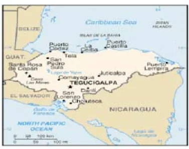
Honduras is a country in Central America, bordered by Guatemala, El Salvador, Nicaragua and both the Caribbean Sea and Pacific Oceans (see Figure 2.1 Map of Honduras (Honduras, 2007)). It is divided into 18 departments, 298 municipalities, 3,731 towns, and 30,591 rural communities. The 2006 population estimate for Honduras is 7.4 million people. Honduran’s live on 112,492 km2 making it the second largest country, by size, in Central America (World Bank, 2006).
Figure 2.1 Map of Honduras
The government is a democratic republic and the country’s economic activities center around agriculture, forestry, hunting, fishing, and manufacturing. Honduras is one of the poorest countries in the Western Hemisphere with a per capita income of $1,170 and 50% of the population living below the poverty line (2006). Consequently, poverty reduction has been and remains the primary development initiative within Honduras. Initiatives to improve water treatment and sanitation services have been a recent phenomenon. A prerequisite for their success in competing for development dollars has been the ability of the project sponsor to demonstrate a close linkage between particular water and sanitation programs and the overarching national goal of poverty alleviation.
2.2 Coverage
In 2004, it was estimated that approximately 68% of Hondurans had access to some form of sanitation services. Approximately 25% of coverage is through domestic connections (such as flush toilets) and the remaining 43% is via latrines. Within urban areas, it is estimated that 88% have coverage. However, sewage transport should not be confused with treatment. It is estimated that only about 10% of collected wastewater is actually treated (SERNA, 2005). This lack of treatment pollutes surface and subsurface water bodies and land.
2.3 Institutions
There have been numerous pilot projects and large-scale water and sanitation initiatives within Honduras run by a variety of organizations ranging from church mission groups to USAID and including many development groups sponsored by other countries. The Honduran water and sanitation sector receives most of its momentum from an assorted collection of international development organizations seeking to assist Honduras in achieving the Millennium Development goals. The national sector itself is spearheaded by a diverse and fragmented set of Honduran institutions.
The Honduran water and sanitation sector underwent a major reform in 2003 due to increasing international pressure from donor agencies. Sector reform was largely driven by the World Bank’s “Poverty Reduction Strategy Plans” and was required for qualification of debt relief. In order to make a strong case for several of the projects proposed, Honduras had to create a new regulatory agency, and restructure the national water utility, SANAA, to include a planning agency. These efforts were not in vain as ultimately Honduras was one of the few countries that qualified for debt relief. In April 2005, Honduras attained its Heavily Indebted Poor Country Completion point and in July 2006 it benefited from the Multilateral Debt Relief Initiative (which translates into development project funding) (World Bank, 2006). Only time will tell if the new agencies will prove sustainable. A more detailed overview of the key institutions involved in the Honduran water and sanitation sector is provided below.
SERNA- Secretaria de Recursos Naturales y Ambiente
SERNA is the environmental protection agency of Honduras. It is charged with protecting a wide variety of broadly defined national sectors such as water, energy, climate and atmosphere, and biodiversity. One of its main missions is to enforce the general environmental protection law established in 1993. In 2005, the organization published a 173-page report on the state of the environment in Honduras (SERNA, 2005). This assessment was funded by the United Nations Environment Program and is one of the better available public compilations of recent countrywide statistics in each sector.
SANAA – Servicio Nacional de Acueductos y Alcantarillados
SANAA is the national autonomous water and sanitation service created by the government of Honduras in 1961 (Water for People, 2006). It historically operated approximately half of the water supply and sewerage systems in Honduras. However, due to the major sector reform in 2003 much of SANAA’s service scope is being decentralized and transferred to the municipalities. This is in part due to SANAA’s reputation for poor service and over staffing (SANAA, 2007b). The Law of the Portable Water and Sanitation Sector created in 2003 mandated this shift. It specifies that the transfer should take place by 2008. After 2008, the main role of SANAA will be as a technical resource for the municipalities.
CONASA – Comisión Nacional de Agua Potable y Saneamiento
Formed as a result of the 2003 Direct Legislation (118-2003) that redistributed SANAA’s power, CONASA’s intended purpose is to function as the planning entity within the new governance structure for this sector. Its mission is to formulate and promote plans and political strategies for the water and sanitation sector. Additionally, the agency is supposed to be the coordinator of
public and private organizations operating in this sector and develop methods for the economic evaluation of water and sanitation projects (CONASA, 2007).
ERSAPS – Ente Regulador de los Servicios de Agua Potable y Saneamiento
ERSAPS was created in 2003 under the water and sanitation reform to function independently from the Ministry of Health and act as a regulatory resource for local system operators of all sizes. The organization was charged with providing the World Bank with the 2006 evaluation report on the transfer of systems from SANAA to the municipal level. Its website provides community leaders of large municipalities and small rural water boards with a comprehensive listing of applicable water and sanitation laws and regulations. It has also assembled several “Technical Manuals” for the municipalities describing these laws and offering advice for implementation. These technical notes do not offer engineering assistance, but rather guidelines for good governance (ERSAPS, 2005).
RAS-HON – Red de Agua y Saneamiento de Honduras
Within Honduras, RAS-HON is a legally incorporated national network designated by Presidential directive as an accessory to the Ministry of Health. RAS-HON was formed in 1992 due to much institutional confusion and limited capacity within the water and sanitation sector. The group was created because of multi-agency identification of the need for a professional network of Environmental Engineers. International development organizations such as the World Bank Water and Sanitation Program, United Nations Development Program, USAID, PAHO/WHO, and UNICEF met with government agencies and nongovernmental organizations in order to create this space for open collaboration. Honduras was the first country in Central America to adapt this sort of forum and it has since spread throughout the region. RAS-HON independently starts activities such as investigations and holds educational seminars (RRAS-CA, 2006).
2.4 Funding
FHIS – Fondo Hondureño de Inversión Social
FHIS, the Honduran Social Investment Fund, is run through the office of the President. It is an important actor in the water and sanitation sector because it receives much of the international aid from groups such as the World Bank. In the last two years, there have been several major loans approved by the World Bank for Honduras that directly affected the Honduran water and sanitation sector. These include the Barrio-Ciudad Project and the Water & Sanitation Sector Modernization Project (FHIS, 2008). FHIS was created in 1990 and there were some complaints that providing funds directly to municipalities for construction, as FHIS did, undermined the roles and missions of non-governmental organizations working in this sector. In 2000, FHIS started trying to reintegrate these groups and their participatory methods into the funding process (Water for People, 2006).
Barrio-Ciudad Project
Approximately $97 million zero-interest credits were provided to Honduras in support of its Poverty Reduction Strategy. Those credits are dedicated to four different purposes, one of them being the Barrio-Ciudad Project. It is comprised of $16.5 million dollars earmarked for improving the life of urban poor. The project runs from 2005 until 2011 and includes funds for
extensions and improvements to city water and sanitation services. Specifically, the project’s planned funding allocations were: improved water supply 40%, sanitation 30%, and sub-national government administration 30%. (Barrio-Ciudad, 2005) In December 2007, the information about the project on the World Bank Website was updated. The funding allocation percentages were shifted substantially to: sub-national government administration 80%, water supply 12% and sanitation 8%. The purported rationale for the shift was obliquely referenced on page 1855 of the World Bank 2007 annual report. Supposedly, part of the original proposal included a municipal loan program as part of a larger total loan request than was ultimately granted by the World Bank. Therefore, when the entire package was reduced, more of the smaller amount of loan money was redistributed to the neighborhood-upgrading component (World Bank, 2007). Of course, this rationale, if true, begs the question of why water supply and sanitation improvements were deemed to be less important/feasible to the poor in the reallocation process.
Water & Sanitation Sector Modernization Project
This project was approved by the World Bank on June 21, 2007 so it is in the initial stages. The timeframe for the program is six years and it calls for a total of $39 million to improve water and sanitation services. $9 million of this is earmarked for natural disaster protection. It is important to remember that in 1998 Hurricane Mitch devastated Honduras and the country is still recovering. The remaining $30 million dollars of the loan is to help municipalities with populations between 40,000 to 300,000 to become autonomous water and sanitation service providers to their residents (World Bank, 2007).
2.5 Existing Systems
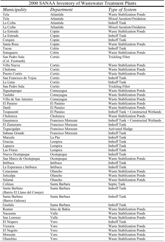
According to SERNA’s 2005 “state of the environment” report, the country operates 41 wastewater treatment systems including 18 Imhoff tanks, 18 waste stabilization ponds, and 5 other technologies (SERNA, 2005). This last category includes the capital of Tegucigalpa, which has an activated sludge treatment plant. However, in Honduras different sources report statistics that do not necessarily agree. During January 2008, an engineer in the infrastructure group of FHIS provided the MIT team with a detailed list of the wastewater treatment facilities in Honduras. The list is from a 2000 survey of wastewater treatment facilities in Honduras by SANAA and includes 51 locations. It is more than likely the most recent and comprehensive survey of such infrastructure in Honduras. Somewhat ironically, it should be noted that the list is still incomplete (for example the Las Vegas Imhoff tanks were not listed). The physical conditions found at each site are unknown.
Interviews during January 2008 with engineers at FHIS and SANAA revealed strong preferences on their part for the use of waste stabilization ponds wherever possible. Imhoff tanks are viewed as a technology of the 1990s whereas the past decade has witnessed the successful implantation of numerous ponds in Honduras. The engineers cite that the ponds are able to provide long enough residence times to kill pathogens and that they store more sludge and therefore do not need to be cleaned as often as Imhoff Tanks. In Honduras, the majority of rivers provide plenty of natural reaeration so factors such as biochemical oxygen demand (BOD) are not as crucial of an issue as pathogen removal (P. Ortiz, personal communication, January 23, 2008). The complete listing of locations and type of treatment systems in Honduras are listed in the Table 2.1 Honduras Wastewater Treatment Systems.
Table 2.1 Honduras Wastewater Treatment Systems (SANAA, 2007a)
2000 SANAA Inventory of Wastewater Treatment Plants
Municipality Department Type of System
Tela Atlantida Waste Stabilization Ponds
Tela Atlantida Mixed Aeration/Oxidation
La Ceiba Atlantida Imhoff Tank
La Ceiba Atlantida Mixed Aeration/Oxidation
La Entrada Copán Waste Stabilization Ponds
La Entrada Copán Imhoff Tank
Corquin Copán Imhoff Tank
Santa Rosa Copán Waste Stabilization Ponds
Tocoa Colón Imhoff Tank
Sonaguera Colón Waste Stabilization Ponds
San Pedro Sula
(Col. Fesitranh) Cortés Trickling Filter
Villa Nueva Cortés Waste Stabilization Ponds
Choloma Cortés Waste Stabilization Ponds
Puerto Cortés Cortés Waste Stabilization Ponds San Francisco de Yojoa Cortés Imhoff Tank
La Lima Cortés Imhoff Tank
San Pedro Sula Cortés Trickling Filter
Siguatepeque Comayagua Waste Stabilization Ponds
Taulabe Comayagua Waste Stabilization Ponds
Villa de San Antonio Comayagua Waste Stabilization Ponds El Paraíso El Paraíso Waste Stabilization Ponds
Danlí El Paraíso Waste Stabilization Ponds
Teupasenti El Paraíso Imhoff Tank + Constructed Wetlands Choluteca Choluteca Waste Stabilization Ponds
Guaymaca Francisco Morazan Imhoff Tank + Constructed Wetlands El Zamorano Francisco Morazan Imhoff Tank
Tegucigalpa Francisco Morazan Activated Sludge Sabana Grande Francisco Morazan Imhoff Tank
Marcala La Páz Imhoff Tank
Gracias Lempira Imhoff Tank
Lapaera Lempira Imhoff Tank
Las Flores Lempira Imhoff Tank
Nueva Ocotepeque Ocotepeque Imhoff Tank
San Marco de Ocotepeque Ocotepeque Waste Stabilization Ponds
Intibuca Intibuca Imhoff Tank
La Esperanza e Intibuca Intibuca Imhoff Tank
Catacamas Olancho Waste Stabilization Ponds
Juticalpa Olancho Waste Stabilization Ponds
Salamá Olancho Waste Stabilization Ponds
Colinas Santa Barbara Septic Tank
Santa Barbara
(Barrio El Llano del Conejo) Santa Barbara Imhoff Tank Santa Barbara
(Barrio Galeras)
Santa Barbara Imhoff Tank
Gualala Santa Barbara Imhoff Tank
Roatan Islas de Bahia Waste Stabilization Ponds
Nacaome Valle Waste Stabilization Ponds
San Lorenzo Valle Waste Stabilization Ponds
El Nispero Yoro Imhoff Tank
Victoria Yoro Waste Stabilization Ponds
El Negrito Yoro Waste Stabilization Ponds
Morazán Yoro Waste Stabilization Ponds
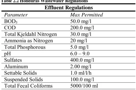
2.6 National Wastewater Regulations
Table 2.2 Honduras Wastewater Regulations (Secretaría, 1997), lists the national effluent
regulations. Enforcement of these regulations falls under the jurisdiction of ERSAPS. In reality, there is little monitoring or penalty imposed on systems that do not conform.
Table 2.2 Honduras Wastewater Regulations
Effluent Regulations
Parameter Max Permitted
BOD5 50.0 mg/l
COD 200.0 mg/l
Total Kjeldahl Nitrogen 30.0 mg/l Ammonia as Nitrogen 20 mg/l Total Phosphorous 5.0 mg/l pH 6.0 – 9.0 Sulfates 400.0 mg/l Aluminum 2.00 mg/l Settable Solids 1.0 ml/l/h Suspended Solids 100.0 mg/l Total Fecal Coliforms 5000/100 ml
3 OVERVIEW OF IMHOFF TANKS
3.1 Background
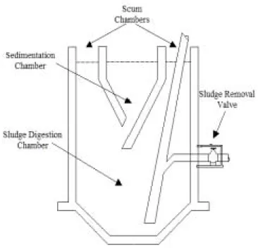
Karl Imhoff invented and patented the Imhoff tank in Germany in 1906 (Herrera, 2006). Over the years Imhoff tanks have had varied designs but characteristic to all is a two-story construction of a sedimentation chamber above a sludge digestion chamber. Figure 3.1 provides a view from the influent/effluent end.
Figure 3.1 Imhoff Tank Schematic
Imhoff tanks function on the premise that the larger particles of total suspended solids (TSS) are removed by first entering the sedimentation chamber and then falling through a small opening into the sludge storage and digestion chamber. In turn, the removal of solids in this manner also decreases the oxygen demand of the wastewater. The removed solids are anaerobically stabilized in the sludge storage chamber through natural biochemical and microbiological reactions until the chamber fills up.
3.2 Mechanics
Flow through the upper sedimentation chamber can be achieved by longitudinal horizontal flow, vertical flow (although rarely utilized), or radial flow. In some locations influent and effluent weirs have been used to distribute flow uniformly throughout the sedimentation chamber (Metcalf, 1935). The sedimentation chamber’s depth must be shallow enough as not to inhibit vertical distribution of flow but also deep enough so that the slow-motion settling zone is not encroached. The 1935 version of the Metcalf & Eddy textbook advises against the use of baffles to aid sedimentation because they tend to produce sub currents. In order to avoid solids
accumulation and decomposition in the sedimentation chamber, it is recommended that a squeegee be used to periodically clean the sides of the sedimentation chamber (1935).
The sludge chamber includes a sludge-storage space and a neutral zone between the storage area and the slot entrance into the sedimentation chamber. In order to utilize the entire tank and avoid an uneven distribution of settled solids it is recommended to reverse the flow every month. It is theoretically possible through employment of the force of gravity to empty the sludge storage chamber by using valves located at the bottom of the tanks. Sludge is removed by flowing through pipes, which extend a short distance inside the hopper. Gas produced within the sludge storage chamber is released through vents into a scum space that must be skimmed every few days to remove floating particles of digested sludge. Care must be paid to keep the water level in the system constant in order to avoid the exchange of contents between the sedimentation and digestion chambers. Differences of hydrostatic pressure can result in surges of sludge up through the slots (Metcalf, 1935). Imhoff tanks are normally constructed with a minimum of two tanks in parallel. This allows the operators to clean one tank without shutting down the entire system.
Expected treatment levels from a properly maintained Imhoff tank are the same as those for isolated sedimentation tanks without a sludge digester. Typically, an Imhoff tank will provide a TSS removal rate of 20% - 70% and 10% - 40% for BOD5 (Reynolds, 1996). The actual removal rate for a specific tank will be a function of influent water quality and tank detention time. In the absence of any additional treatment, the sedimentation process will not yield substantial reductions in other important water quality indicators such as total coliform counts or nutrient loading from phosphorus and nitrogen.
The solids that settle into the bottom storage chamber of the Imhoff tank are termed sludge and undergo anaerobic digestion. Anaerobic digestion is a four-stage process of hydrolysis, acidogenesis, acetogenesis, and methanogenesis that causes considerable change to the physical, chemical, and biological properties of the sludge (Mara, 2004). Microbes that thrive in the absence of molecular oxygen liquefy the solids, digest the soluble solids and produce gas. The two main groups of microbes that do this work are organic-acid-forming heterotrophs and methane-producing heterotrophs. Complex organic substrates such as carbohydrates, fats, oils and proteins are broken down by the organic-acid-forming heterotrophs. These microorganisms are resilient to a wide range of pH. The methane-producing heterotrophs produce methane and carbon dioxide from the organic acids. These microorganisms grow slowly and require pH ranges of 6.7 to 7.4 and serve as the rate-limiting step in the anaerobic digestion process. Before digestion the volatile solids constitute 65-75% of the sludge’s composition whereas after digestion the volatile solids are reduced to 32%-48%. The end result of successful anaerobic digestion is stable solids that will not degrade and from which water will easily separate (Reynolds, 1996). After the digestion process is complete, the sludge may be removed from the Imhoff tank and be dewatered on a sludge drying bed or by other equivalent means.
3.3 Design Criteria
Table 3.1 includes design criteria that were adapted from the 3rd edition of “Wastewater Engineering: Treatment, Disposal, and Reuse.” by Metcalf and Eddy, Inc (Tchobanoglous, 1991).
Table 3.1 Design Criteria for Unheated Imhoff Tanks (Herrera, 2006)
3.4 Advantages
Imhoff tanks remain a viable treatment option in certain developing communities for several reasons. An Imhoff tank is a low maintenance, low cost option in comparison to activated sludge treatment. Primary treatment through sedimentation offers the possibility of reducing the negative environmental and human health effects of untreated sewage to low enough levels that natural processes such as dilution and biodegradation can accomplish adequate remaining treatment. Of course, the effectiveness of these latter treatment modalities depends significantly on the natural assimilation capacity of receiving land and water bodies. Additionally, Imhoff tanks do not need the large amounts of flat land that waste stabilization ponds or constructed wetlands require. In the mountainous terrain of Honduras this advantage is significant. They also provide storage and gravity removal mechanisms for digested sludge that plain sedimentation basins do not. Further, with proper planning Imhoff tanks may later be coupled with applicable forms of secondary and tertiary treatment as need and capital becomes available to a community for investment in the facilities required for such treatment.
4 OVERVIEW OF CEPT
4.1 Introduction
Chemical treatment of wastewater involves the use of coagulants such as metal salts to bind together suspended solids. Larger conglomerations of suspended solids will produce increased particle removal through gravitational settling. In the CEPT process, the high removal rates of suspended solids (commonly around 80%) are accompanied by an increased removal of BOD (around 40-60%). Examples of chemical additives to wastewater are alum, ferric chloride, ferric sulfate, and lime. Adding chemicals to wastewater is not a new treatment process. As early as the 1870s, there are reports of its use in England. In fact, during the early 1900s it was also commonly utilized in the United States. This was before the development and widespread adoption of biological treatment (Parker, 2001). The most common complaints associated with the early use of CEPT were chemical expense and large quantities of sludge produced that required disposal (Harleman, 2001). However, research suggests that chemical costs can be reduced through employment of lower dosages of chemicals than traditionally used. Those original chemical dosage levels were on the order of magnitude of 200-300 mg/l of the metal salt. During the 1980s, in the United States lower dosages of metal salts (on the range of 20-40 mg/l) were coupled with polymers as flocculants (Harleman, 1998).
4.2 History
Documentation exists for the use of low-dose CEPT during the 1960s when the Great Lakes of the Midwestern United States were experiencing a substantial amount of eutrophication. The equipment vendor Dorr Oliver championed the process of adding small amounts of lime before activated sludge treatment in order to meet phosphorus treatment objectives. During the same time, Dow Chemical developed a CEPT process featuring the addition of ferric chloride and polymer to untreated wastewater. Dow’s process was piloted in Michigan and later its use was expanded to other Midwestern cities in the United States. Furthermore, several plants were developed during the 1980s in Windsor and Sarnia in Ontario, Canada that also utilized CEPT to help address the eutrophication of Lake Huron (Parker, 2001).
CEPT has also been at the forefront of controversies within the United States over the necessary degree of treatment of wastewater before disposal through ocean outfalls. In California engineers and scientists at the Point Loma plant in San Diego successfully obtained a waiver from Congress to avoid the construction of a secondary treatment facility. This was done through demonstrations that there would be no degradation of the ocean following CEPT. Their argument attacked the mandate for use of technology based wastewater treatment modalities rather than the establishment of percent removal goals based on the assimilative capacity of the receiving waters. Additionally, during the time of the Boston Harbor cleanup in Massachusetts, the late Professor Donald Harleman from the MIT Civil and Environmental Engineering department campaigned vigorously for the incorporation of CEPT into the treatment scheme. He asserted that CEPT plus an ocean outfall or CEPT plus secondary treatment plus outfall would save money. Ultimately in this situation CEPT was not incorporated but the concept received international attention (Morrissey, 1992).
About the same time as the Boston Harbor cleanup, the efforts of Professor Harelman’s research group at MIT focused on the application and applicability of CEPT to the developing world. During the mid-90s current MIT lecturer Susan Murcott performed pilot studies in places such as Mexico City, Hong Kong, and several cities in Scandinavia. Her work involved numerous bench scale tests and a few pilot applications of CEPT, as well as the gathering of CEPT case studies. In Mexico City, it was estimated that the operation and maintenance costs of a CEPT plant were comparable to those of a conventional activated sludge plant due to predictions that savings in energy expenses would recover the increased chemical costs. On the other hand, the capital costs of a CEPT plant were forecast to be half as much of that of an activated sludge plant due to the reduced number of necessary sedimentation basins. During pilot testing CEPT was able to achieve similar amounts of removal of helminth eggs (a significant problem for Mexico city) as activated sludge plants. While CEPT removed less organic matter, this was actually viewed as beneficial since peasant farmers utilize the wastewater effluent for agricultural irrigation (Murcott, 1996).
The Stone Cutter’s Island plant in Hong Kong started operating in July of 1997. At the time it was the world’s largest CEPT plant with a maximum capacity of 40 m3/sec. Initially the plant was not going to incorporate CEPT. However, after a favorable report by an international review panel CEPT was incorporated into the design. Through the use of a combination of ferric chloride, an anionic polymer, and seawater, the number of required settling tanks was reduced from 58 to 38. On average, from 1997 –2000 the plant saw 84% suspended solids removal efficiency and 75% BOD removal efficiency attributed to CEPT (MIT, 2003). Experiences in Scandinavian countries produced similar results. Through low-dose CEPT more suspended solids and BOD were removed. As a result, surface overflow rates could be increased thereby reducing the number of necessary sedimentation basins (Murcott, 1994).
A number of CEPT studies have been conducted as MIT MEng thesis projects. The bulk of these projects center around fieldwork conducted in Brazil. Their foci range from the modeling of CEPT in waste stabilization lagoons to full conceptual models of plants for particular cities. Students have also researched the use of seawater as a coagulant aid in the CEPT process (MIT, 2003). While CEPT has seen widespread global use, the vast variations of application in terms of the quantities and combinations of chemicals and the locations of the injection points in the treatment process are staggering. This may be directly attributed to the numerous regional differences in water quality, varied treatment objectives, and chemical availability. CEPT can be effectively studied by breaking down the process into the various physical phenomena involved. There is substantial research available on flocculation, coagulation, and sedimentation of wastewater. This research may be used as a framework when considering the use situation of CEPT coupled with an Imhoff tank. The remainder of this chapter attempts to summarize some of the key issues that were identified as a result of a literature review and relate them to the use of CEPT as part of wastewater treatment in an Imhoff tank.
4.3 Coagulation/Flocculation
Wastewater is composed of some suspended material that is naturally settleable and some that is nonsettleable. A significant portion of the nonsettleable suspended material is colloidal matter. Colloids range in size from 10-6 mm – 10-3 mm and tend to have a high specific surface area. Colloids also have a tendency to develop an electrostatic charge and adsorb substances. It is desirable to remove colloidal particulates because they may harbor pathogens and exert an oxygen demand. However, colloids stay in suspension because the repulsive force of other colloids produce a stabile electrostatic force that prevents settling through operation of gravity. The relative stability of a colloidal suspension can quantified through calculating its zeta potential: D qd π ζ = 4 ζ = zeta potential q = charge per unit area
d = thickness of layer surrounding the shear surface through which the charge is effective D = dielectric constant of the liquid. (Reynolds, 1996)
The greater the zeta potential the more stable the suspension.
The process of destabilization and initial aggregation of colloidal and fine suspended solids is called coagulation. Through the addition and rapid mixing of a coagulant, the zeta potential is decreased enough so that van der Waals forces can attract the particulates, thus helping them to coalesce. Most naturally occurring colloids are negative while most coagulant salts (when added to water) dissociate, undergo hydrolysis, and create positively charged complexes (Reynolds, 1996). These highly positive charges are then absorbed on the surface of the negative colloids. Additionally, particles aggregate through interparticle bridging until a “floc” consisting of the enmeshed suspended particles is precipitated.
The process of flocculation is furthered by a slow stirring or gentle agitation to bring the destabilized particles together. The goal is to produce a rapid-settling floc. Settling of a floc is governed by Stoke’s law for Reynolds Numbers less than 0.3 (Tchobanoglous, 1991).
µ ρ ρ 18 ) ( g 2 d s Vc = −
Vc = terminal velocity of particle ρs = density of particle
g = acceleration due to gravity µ = dynamic viscosity
d = particle diameter ρ = density of fluid
Given that the settling velocity is directly proportional to the square of the particle diameter, in order to produce a rapid-settling floc the goal of flocculation goal is to grow the size of the flocs.
As the diameter of the particles grow the settling characteristics of the particles are classically determined experimentally through a settling column.
Flocculation basins are typically furnished with mechanical agitators (i.e. paddle wheels), pneumatic agitators, or baffles in order to provide gentle mixing. The main design parameter, the velocity gradient (G), is used to evaluate the degree of mixing.
V P G
µ
=
P = power imparted to the wastewater V = basin volume
µ = absolute viscosity of the wastewater
The velocity gradient is proportional to the rate of particulate collisions and the total number of collisions is proportional to the product of G and the detention time T (Reynolds, 1996). Care must be taken because if G is too large flocs may break apart.
For Imhoff tanks without chemicals, coagulation and flocculation occur more or less simultaneously in the upper sedimentation chamber of the tank rather than in a separate flocculation basin. Two types of particle contact produce agglomeration of particles: velocity gradients in the tank and differential settling rates (EPA, 1975). In general, due to the larger particulates in wastewater, flocculation occurs with relative ease and the required values of “G” multiplied by detention time “T” are much less than those for drinking water treatment (GT = 10,000-100,000 for wastewater vs. 30,000-210,000 for drinking water) (Reynolds, 1996). Still, wastewater treatment designs also frequently utilize mechanical agitators. Other techniques such as ballasted flocculation of wastewaters streams are employed to augment natural flocculation processes.
Imhoff tanks commonly utilize either the influent channels and/or the sedimentation chamber for coagulation and flocculation. In the case of water treatment it has been demonstrated that flocculation can occur in the influent channel if chemical addition is far enough upstream (Shultz, 1992). For wastewater treatment, this can be viewed as both a blessing and a curse. While it is a good thing that new basins do not necessarily need to be added, a substantial amount of sludge could form within the channel and removal mechanisms would need to be incorporated into the design and operating protocols.
4.4 Chemicals
A wide variety of chemicals have been successfully used for CEPT. Aluminum sulfate “alum” is the most frequently used coagulant because it is generally the cheapest and is readily obtainable in lump, ground, and liquid forms. The optimum pH range for alum is 4.5 to 8.0 (because it is relatively insoluble over this range). Iron salts on the other hand are effective over a wider pH range. For example, ferric sulfate and ferric chloride are relatively insoluble on a pH range of 4 to 12. Additionally, the flocs formed by iron salts are denser than those of alum and therefore settle more rapidly. Flocculant aids are frequently added in low dosages (less than 0.3 mg/l) in
order to reduce the necessary quantities of primary coagulants and obtain optimum coagulation. However, most polyelectrolytes are synthetic chemicals and prohibitively expensive in developing countries (Reynolds, 1996). Occasionally natural polymers from plants and animals (i.e. fish eyes) are utilized (Shultz, 1992). Adjustment of alkalinity and pH is typically done through the use of lime. Most case studies by MIT students in Brazil found that a substantially smaller quantity of ferric chloride as the coagulant produced similar suspended solids and BOD removal rates as compared to alum (MIT, 2003). Ultimately however, in order to determine the optimal dosage of coagulant for a particular wastewater stream, it must be put through bench scale jar testing and pilot runs.
4.5 Sedimentation
Thomas Camp largely developed the theories driving the design of sedimentation basins. Through the demarcation of an ideal settling zone and by considering the trajectory of the slowest settling particle that would be completely removed, he was able to demonstrate the relationship between sedimentation velocity and the theoretical performance of sedimentation tanks. As a result he emphasized the surface-overflow rate: flow/area, rather than hydraulic retention time, as the driving factor in designing an ideal sedimentation tank. The design parameters proposed by Camp are widely utilized in industry to design sedimentation tanks. Over many years of practice, it has also been recognized that Camp’s theoretical values are not so easily obtained. Camp’s initial assumptions included prerequisites for the application of his theories that are commonly not achieved in the field. Camp recognized that when flocculation occurs it complicates the model of designing sedimentation tanks solely based on surface overflow rates. Secondly, he assumed that all particles reaching the bottom of the ideal settling zone remained indefinitely removed. In practice however, scouring does occur and affects the performance of settling basins. Finally, he assumed that an adequate velocity distribution is achieved at the inlet (Dick, 1982). Thus, his assumptions led Camp to encourage the use of shallow basins, which rely on high forward velocities for particle agglomeration. However actual trends in the U.S. seem to favor deeper tanks that rely on differential settling for particle agglomeration. These designs are based on the proposition that at high forward velocities there is little flocculation achieved. Studies show that raw sewage agglomerates slowly under differential settling conditions so detention time can have a significant effect on settling tank performance (EPA, 1975).
All of these complications directly apply to the use of CEPT in an Imhoff tank. Addition of chemicals causes flocculation within the Imhoff tank making the prediction of the amounts of settling much more challenging. Inlet and outlet designs may not evenly distribute the flow. Further, if operated at high overflow rates Imhoff tanks may still experience solids scouring despite the settling of sludge by inclined plates into a separate digester.
5 LAS
VEGAS
5.1 Geography
Las Vegas (Figure 5.1 (Google, 2008)) is located in the department of Santa Barbara, which is the 9th most populated department in the country. The municipality of Las Vegas is located just west (14º 52’ N, 88º 4’ W) of the largest freshwater lake in Honduras, Lake Yojoa. Lake Yojoa is situated 125 kilometers northwest of the capital of Honduras, Tegucigalpa, and 75 kilometers south of the industrial capital of Honduras, San Pedro Sula.
Figure 5.1 Las Vegas
The region of Las Vegas gained the status of township on September 8, 1987 and formally became a municipality on December 17, 1997 (Herrera, 2006).
Lake Yojoa is a valued natural resource in the area and a major center for industry and tourism in Honduras. The municipalities of Santa Cruz de Yojoa, Cortés, Taulabé, Comayagua, and San Pedro de Zacapa all border the lake. Some of the most notable businesses in the vicinity include Aqua Finca, Saint Peter Fish, a tilapia fish farm owned by a Swiss proprietor that has operated in Honduras since 1997. Additionally, the mining operation, American Pacific Mining Corporation, AMPAC, began operations in the area in 1948. Since then AMPAC has experienced several operational changes. The mine has been owned and operated since 1990 by the trans-Canadian organization, Breakwater. It is the biggest mine in Central America, primarily mining zinc, and provides employment to more than 200 people from Las Vegas (Trate, 2006). El Mochito, the neighborhood in which AMPAC is located, falls within the jurisdiction of the municipality of Las Vegas. Therefore the mine provides substantial funding for city projects.
5.2 Population
The total population of urban Las Vegas is approximately 17,400 and is spread among the four neighborhoods of El Mochito, San Juan, Las Vegas Central, and Las Vegas North. The neighborhood of Las Vegas Central makes up the urban center for the municipality. In addition to some residential housing, shops, the central park, the main soccer field and the municipal building are all located in this area. The number of dwellings in Figure 5.2 refers only to legal connections to the water system.
Figure 5.2 Las Vegas Urban Neighborhoods
5.3 Water and Wastewater Treatment
The water supply for the municipality of Las Vegas is currently not treated but comes from mountain springs. The city engineers are considering chlorination for portions of the distribution system. Bottled water from vendors is readily available. No investigation into how many people use tap water versus purchasing water was conducted nor is the author aware of another study. One major concern of the city engineers is severe scaling in the water pipes, which is forcing frequent replacement.
Currently wastewater treatment in Las Vegas consists of two Imhoff tanks constructed in parallel and which service a group of dwellings in Las Vegas Central. City engineers estimate the Imhoff tanks service roughly 3,600 residents (6 residents per dwelling times 600 dwellings). Wastewater in the neighborhoods of El Mochito and San Juan are serviced by septic tanks or discharge directly into the river. A wastewater collector is currently under construction for the neighborhood of Las Vegas North through a grant from the government of Taiwan. A major question is where the wastewater will go for treatment, if any, after this new collector is built. In the short term, it will probably go directly into the river. The city engineers expressed interest in whether the existing Imhoff tanks could handle this additional flow. If it could not be routed to the existing Imhoff tanks, they were also interested in knowing our opinions on what other forms
of wastewater treatment infrastructure they should consider building. In reality, all of the current wastewater systems in Las Vegas are best described as wastewater collection devices that in some cases provide only a minimal amount of treatment through removal of solids.
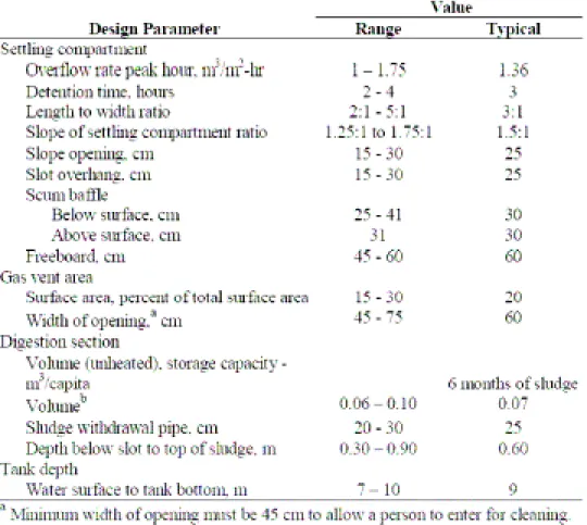
5.4 Imhoff Tanks
The Imhoff tanks (Figures 5.3 – 5.6) were built in Las Vegas in 1992 with capital funds provided by FHIS. The system consists of two tanks in parallel originally designed to serve 4,000 residents producing 250 liters/person/day of wastewater. They were designed by the SANAA engineer Pedro Ortiz and constructed under the supervision of the nongovernmental organization Agua Para el Pueblo (APP). According to the Executive Director of APP, their construction was part of a program to create construction jobs in the area (J. Nuñez, personal communication, January 23, 2008). Originally there were plans to build a large septic tank with a drainfield on land adjacent to the Imhoff tanks. However funds ran short and this was never completed. A road now occupies this piece of land.
Figure 5.6 Sludge Valves
Figure 5.3 Las Vegas Imhoff Tanks Figure 5.4 Top View
(Influent lower left corner, Effluent upper right corner)
5.4.1 Service Area
As noted above, the Imhoff tanks service a part of Las Vegas Central (the area between Piedras Amarillas and Raices Creek). A more detailed depiction of this area is provided in Figure 5.7. Exact locations of upstream piping connected to the Imhoff tanks are not documented. Again, it is estimated that roughly 600 houses are connected to the system (and at 6 people per household 3,600 people). Some of these connections are illegal.
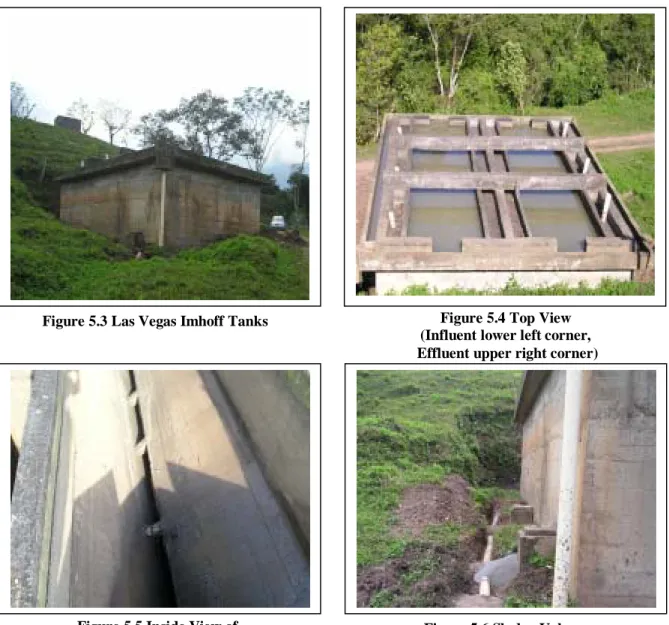
5.4.2 Dimensions
Ari Herrera measured the dimensions for the plan view in Figure 5.8 during the summer of 2006. Each Imhoff tank contains three conical wells to which sludge valves and discharge pipes are connected. The dimensions for these wells are shown in Figure 5.9. The depth dimensions in Figure 5.9 are taken from the original construction plans supplied by the contractors APP. The surface area in the plan view of Figure 5.9 includes the scum and bypass channels for one tank.
Figure 5.9 Dimensions of One Las Vegas Imhoff Tank
The channel upstream of the Imhoff tank is shown in Figure 5.10. The channel is constructed of a 12-inch diameter cast-in-place concrete pipe. There are three uncovered openings in the channel. The three elevation points marked “E” were measured relative to an arbitrary datum of 100 m at the box farthest from the Imhoff tank. These elevations were taken from the top of the concrete structure not the water surface.
Figure 5.10 Dimensions of Upstream Channel (not to scale)
5.4.3 Flows
Experco International, a Canadian environmental engineering consulting firm, measured the flows on the Imhoff tank in a 2003 study. The graphs in Figure 5.11 show flow data for roughly a 26-hour period. The depth data suggests that the flows were calculated by measuring the height of water in the influent channel coupled with a travel time or other method to determine velocities. It is unknown what type of equipment was used to obtain these measurements. The flow to the Imhoff tank throughout the day is not constant, however it is possible to see a distinct diurnal pattern. Based upon the 2003 study, from 6am – 5pm one should design for a peak flow of 142 m3/h. From 5pm – 12am there are significant fluctuations, but one could design for an average flow of 69 m3/h. As the city is sleeping from 12am – 6am the flow in the system drops down to around 20 m3/h.
Matthew Hodge also measured flows during January 2008. Small tangerines were dropped in a straight portion of the influent channel. The depth of water and travel time along a known distance were recorded and used to calculate the flows. It should be noted that the tangerines might not precisely represent the flowrate since they floated along the top of the water, which would contain the fastest moving layer of the water column.
Table 5.1 January 2008 Flows (Hodge, 2008)
Date Time Flow Rate
m3/h 1/16/2008 09:30 191 1/16/2008 14:30 191 1/17/2008 04:30 103 1/17/2008 10:00 173 1/19/2006 14:00 161 1/20/2008 10:00 180 1/21/2008 09:30 164 1/25/2008 15:00 145 1/29/2008 10:45 170 1/29/2008 12:00 156 1/29/2008 12:30 149 1/29/2008 13:00 153
The results suggest a similar pattern to the day as Experco’s 2003 study. However, the actual quantities of flow are higher. The average value during the peak period of 6am – 5pm was 180 m3/h. This may be due to the seasonal differences between April and January, more connections since 2003, increased water usage, or differences in the method of measuring flow. Additionally at 4:30 am, when one would expect low flows due to nighttime inactivity, the flow to the system was measured to be 103 m3/h!
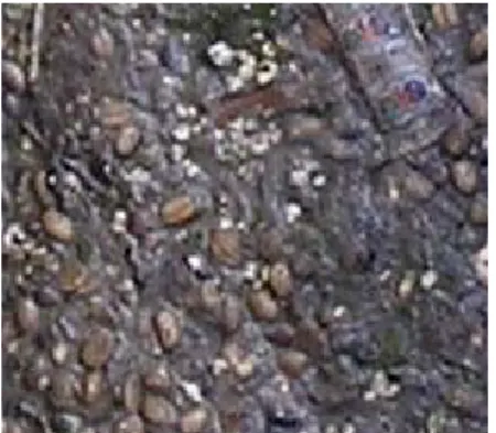
This staggering amount of early morning flow can be attributed to a combination of factors. According to the plumbers in Las Vegas from November – January many residents de-pulp coffee beans in their homes. In order to harvest the beans, the coffee berry must first be de-shelled. Many farmers bring the coffee berries home and leave them under running water throughout the night. The combination of softening and mechanical separation induced by the flowing water removes the shell. However, it also uses a lot of water. Dry methods exist for de-pulping coffee, but reputedly at the expense of altering flavor. During January 2008, the scum chambers in the Imhoff tanks accumulated a lot of coffee beans (Figure 5.12), suggesting this is a major issue. Other reasons for high flows during the nighttime include a large number of leaky faucets in the town as well as groundwater infiltration into the waste stream.
Figure 5.12 Coffee Beans in Scum Chamber
The data from the Experco 2003 study and January 2008 Hodge study do not represent the variations in seasonal flow. During the rainy season (May-September) the plumbers mentioned that the majority of the freeboard in the sedimentation tank is utilized. One is also able to visually observe these high water marks on the interior sides of the tanks. Fred Stottlemyer, director of the International Rural Water Associations Honduras projects, has worked in Honduras for over 10 years. He estimates that during the rainy seasons surface and groundwater infiltration increases flow into the system by 200% (F. Stottlemyer, personal communication, January 11, 2008). This quantity would not only place an extremely large amount of “extra” water flow on the system, but also substantially dilute the actual wastewater loads.
5.4.4 Loads
During the same 2003 study mentioned above, Experco measured the load on the Imhoff tank. The sampling regime for this study is unknown so it is not clear if the results are from a single grab sample or averaged over the course of the study. All samples were preserved by the norms established by “Standard Methods.” The data for Experco in Table 5.2 is taken from Herrera (2006).
The work in January 2008 focused on total suspended solids (TSS), total coliforms, and BOD/COD as performance metrics. The reported values are averaged from all of the tests run by Mattthew Hodge (TSSin n = 5, TSSef n = 6, CODin n = 3, CODef n = 5, BODin n= 4, BODef n = 2, TCin n = 1, TCef n = 3) (Hodge, 2008). Measurements were taken using the following methods before any structural changes (such as the introduction of baffles and gates that will be described in section 5.4.5 Maintenance):
Total Suspended Solids
The most prevalent and recommended method to measure TSS is the “Total Suspended Solids Gravimetric Method” (Standard Method 2540). This method was used for the influent and effluent testing of the Las Vegas Imhoff tank. TSS is a measure of both suspended solids and dissolved solids. Typical municipal wastewater has a TSS of between 450 and 1250 mg/L (Reynolds, 1996).
Chemical Oxygen Demand
Chemical Oxygen Demand (COD) is a measure of the oxygen required to chemically oxidize all of the organic material in a water sample. To test the COD of water samples in this project the HACH Chemical Oxygen Demand Colorimetric Method (Method 8000) was used.
Biochemical Oxygen Demand
Biochemical Oxygen Demand (BOD) is a measure of the oxygen needed for aerobic microbes to fully decompose organic wastes in water. This is a more relevant water quality measurement than COD, but requires more time (typically a BOD5 day test) than COD tests. The method that was used to test BOD5 was Standard Method 5210.
Total Fecal Coliforms and E. Coli
Total Fecal Coliforms is a measure of the total microbial activity in a water sample. It is used as a surrogate for a measure of pathogens in the water. Typically an absence of coliforms correlates to an absence of pathogens. The approved method for measuring coliforms is the “Membrane Filter Technique for Members of the Coliform Group” (Standard Method 9222). Due to limitations of onsite laboratory equipment, another testing method was utilized in place of the standard method. 3M E.Coli/Coliform Petrifilm Count Plates were used to measure total fecal coliforms in this project.
Table 5.2 Las Vegas Imhoff Tank Loads (Herrera, 2006 & Hodge, 2008)
Experco 2003 MIT January 2008 Parameter Units Regulation Influent Effluent Influent Effluent
pH 6.0 - 9.0 7.36 7.26 8.0 Conductivity µs/cm 474 479 Settlable Solids mL/L/hr 1 3.5 2.5 Total Suspended Solids mg/L 100 205 110 190 140 Ammonia Nitrogen mg/L 20 8.96 10.64 TKN mg/L 30 10.64 11.76 Nitrites mg/L <0.01 <0.01 Nitrates mg/L 0.01 0.07 Total P mg/L 5 3.50 3.70 Fecal Coliforms UFC/
100 mL
5E+03 4E+07 5E+07 5E+08 1.8E+09 Fats and Oils mg/L 10 29.56 27.43
COD mg/L of O2 200 220 227 320 260 BOD mg/L of O2 50 123 138 150 120
At the times of our measurements, the Imhoff tanks were not performing as well as they were in 2003 for TSS and Fecal Coliforms. The tanks were achieving an average of 26% removal of
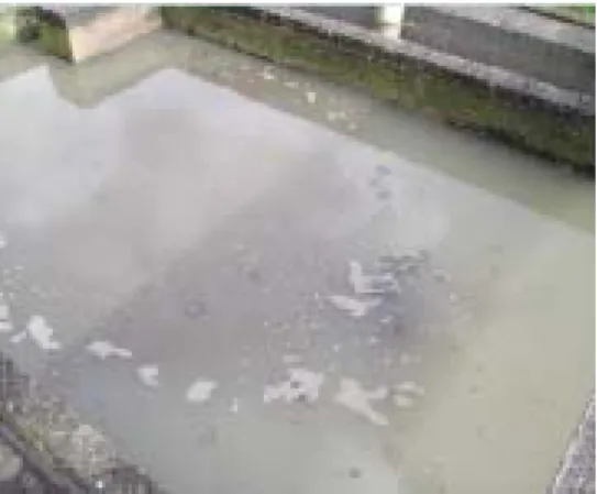
TSS whereas in 2003 it was 46%. The tanks were also experiencing an increase of 260% for fecal coliforms whereas in 2003 the increase was only 25%. However, it is difficult to make a direct comparison because we do not know if the Experco results are representative of average conditions during 2003. The poor performance may be connected to high flow through the system. High flow results in shorter detention times and in turn less settling. Additionally high flow can cause scouring, which causes partially digested sludge to surface and be discharged with the effluent before it has time to settle. During January these types of plumes were observed (Figure 5.12) and are suspected to have caused the increase in fecal coliforms. COD and BOD5 performance during 2008 improved, but neither meets applicable regulatory standards.
Figure 5.13 Scouring
5.4.5 Maintenance Sludge Removal
The Las Vegas Imhoff tanks did not receive maintenance until December 2007. As preparation for the MIT January 2008 tests, the municipality cleaned the digestion chambers for the first time since construction in 1992. The procedure took three men two days. Sand and other compacted solids clogged the valves at the base of the tank that were constructed for sludge removal. This resulted in several of the discharge pipes needing replacement after the cleaning. The sludge was emptied from the digestion chamber by rope and bucket. After removal it was buried along side of the Imhoff tanks since a sludge drying bed does not exist. Despite lack of sludge removal for 16 years, the tanks are in good structural condition. Hodge recommended to the municipality that it removes sludge (approximately 47 m3) semi-annually and design and build a sludge drying bed adjacent the Imhoff tanks (Hodge, 2008).
Flow
The distribution of flow between the two Imhoff tanks is inherently uneven. This results in unequal residence times and less than optimal removal of solids. There are several correctable causes of uneven flow distribution. The first is poor quality and improperly utilized flow gates. Flow gates should be located in eight positions in the bypass channel that surrounds the sedimentation chambers. The flow gates should be used to bypass the sedimentation chambers during cleaning. They should also be used to reverse the flow so that solids will be deposited along the entire length of the digestion chamber rather than primarily in the effluent end.
Flow gates were all together missing at the start of January 2008. We constructed wooden gates in January, but it was difficult to create a seal and so many short-circuited. Placing a rubber tire along the cement-wood interface did not help to correct this issue. The plumbers of Las Vegas came up with the idea of using bags of sand as further means to block the flow behind each wooden flow gate. The bags are easier to remove and did a better job than the wooden flow gates alone. Finally, if the proper placement of flow gate locations in order to maximize their effectiveness is not intuitively obvious, (Herrera, 2006) contains sketches trying to explain placement procedure. The MIT team recommended that the municipality maintain eight flow gates consisting of the wooden planks and bags of sand (Figure 5.14) and to use them monthly to reverse the flow through the system.
Figure 5.14 Wooden + Sand Bag Flow Gate
Additionally, the inlets into the sedimentation chambers do not facilitate even flow distribution between and within the two Imhoff tanks. Wooden baffles with two rows of holes were installed during January 2008 to even out the flow (Figure 5.15).
Approximately 13 holes per row were installed using a hand drill. They were approximately one inch in diameter and spaced one inch apart. The positioning and size of the holes were determined through trial and error. First a single line of holes was created, then a second. The original boards did not provide enough free board in the influent channel when the holes became clogged, so the boards were cut shorter. The ultimate goal is to have an even amount of flow in both Imhoff tanks and for that flow to spread across the entire width of the sedimentation chambers. While the baffles do help to even out the flow distribution they also clog very easily because the overall system does not possess a grit chamber. Plastic bags and large pieces of feces block the holes after several hours. Once the holes are blocked the water flows over the top of the baffles. Nevertheless the flow between the tanks was still better distributed than without the baffles. Cleaning the baffles requires poking a stick in the holes and removing plastic bags. It was observed that this transforms the influent channel into a grit chamber where many more solids are deposited. An effort must be taken to clean the influent channel out on a daily basis and the baffles several times a day.
Scum
Gases generated during sludge digestion produce bubbles that rise to the surface of the tank carrying with them partly digested pieces of solids. The majority of the gas and solids rise in the scum chamber portion of the tank. As a result a layer of solid crust forms in the scum chambers (Figure 5.16). This layer must be routinely broken up in each of the four scum chambers to afford an easy escape of gas from the digestion chamber. The operator can construct a scraper similar to the one shown in Figure 5.16 that is used by the operator in Marcala, La Paz. It is recommended to removal scum from the four scum chambers and sedimentation chamber bi-weekly.
Sedimentation Chamber
In order to achieve the highest possible levels of solids removal from the sedimentation chamber an operator needs to routinely clean the tanks. A rubber squeegee can be used along the sloping walls of the settling compartment to remove any solid material. This can be performed while the tanks are full of water. This prevents scouring and deposits the material into the lower digestion