Publisher’s version / Version de l'éditeur:
Vous avez des questions? Nous pouvons vous aider. Pour communiquer directement avec un auteur, consultez la première page de la revue dans laquelle son article a été publié afin de trouver ses coordonnées. Si vous n’arrivez pas à les repérer, communiquez avec nous à [email protected].
Questions? Contact the NRC Publications Archive team at
[email protected]. If you wish to email the authors directly, please see the first page of the publication for their contact information.
https://publications-cnrc.canada.ca/fra/droits
L’accès à ce site Web et l’utilisation de son contenu sont assujettis aux conditions présentées dans le site LISEZ CES CONDITIONS ATTENTIVEMENT AVANT D’UTILISER CE SITE WEB.
Paper (National Research Council of Canada. Institute for Research in
Construction), 1987
READ THESE TERMS AND CONDITIONS CAREFULLY BEFORE USING THIS WEBSITE. https://nrc-publications.canada.ca/eng/copyright
NRC Publications Archive Record / Notice des Archives des publications du CNRC : https://nrc-publications.canada.ca/eng/view/object/?id=2c28c0e9-603c-478f-a5b2-682439b03523 https://publications-cnrc.canada.ca/fra/voir/objet/?id=2c28c0e9-603c-478f-a5b2-682439b03523
NRC Publications Archive
Archives des publications du CNRC
This publication could be one of several versions: author’s original, accepted manuscript or the publisher’s version. / La version de cette publication peut être l’une des suivantes : la version prépublication de l’auteur, la version acceptée du manuscrit ou la version de l’éditeur.
For the publisher’s version, please access the DOI link below./ Pour consulter la version de l’éditeur, utilisez le lien DOI ci-dessous.
https://doi.org/10.4224/40001376
Access and use of this website and the material on it are subject to the Terms and Conditions set forth at
Fire drainage system
Ser TH1
N21d National Research Conseil national no. 1479
k
~ancll c a m de n c h e r n h6. 2
BLDC
Institute for lnstitut de Research in recherche en-- Construction construction
Fire
Drainage System
by T.Z. Harmathy and I. Oleszkiewicz
Reprinted from A N A L Y Z E D
Fire Technology
Vol. 23. No. 1. Februaw 1987 p. 26-48
(IRC Paper No. 1459)
Price $3.00 NRCC 27714
p r d v i s i o n d ' i n c e n d i e s h y p o t h d t i q u e s se p r o p a g e a n t p a r d e s t r u c t i o n d e s p a r o i s d e compartiments s u c c e s s i f s , Un nouveau syst3me d e s k c u r i t d i n c e n d i e , a p p e l e "systsme d e confinement du f e u " , e s t c o q u pour l u t t e r c o n t r e les i n c e n d i e s r g e l s , q u i se propagent e s s e n t i e l l e m e n t p a r convection. Ce systsme l i m i t e l e f e u e t l a fum6e B l a p i e c e d ' o r i g i n e e t B une s e c t i o n d e c o u l o i r a d j a c e n t e . I1 p e u t S t r e concu d e f a c o n a f o n c t i o n n e r s a n s e a u e t s a n s 6 l e c t r i c i t B . Le p r e s e n t document d e c r i t les p r i n c i p e s e s s e n t i e l s du systeme e t f a i t S t a t d e q u e l q u e s r 6 s u l t a t s exp6rimentaux.
Fire Drainage System
by T. Z. Harmathy and I. Oleszkiewicz
Reprinted from FIRE TECHNOLOGY Volume 23, Number 1
February 1987 Pages 26-48
Copyright O National Fire Protection Association. All Rights Reserved.
Fire
Drainage
System
T. Z. HARMATHYI. OLESZKIEWICZ
National Research Council of Canada
(Manuscript received October 1985, accepted September 1986)
Present firesafety measures were conceived to deal with hypo- thetical fires spreading by destruction of successive compartment boundaries. A new firesafety system, referred to as the "fire drainage system," is designed to cope with real-world fires spreading mainly by convection. I t confines fire and smoke to the room of origin and to
a small corridor element adjacent to the room. The system can be de- signed to operate without the use of water and electric energy. The fundamentals of its design are described and some experimental in-
formation is presented.
INTRODUCTION
HE ESTABLISHED THEORY of fire protection is based on the
T
assumption that fire spreads through a building by either conduction of heat through the compartment boundaries, followed by ignition of com- bustible items in the neighboring spaces, or collapse or partial failure of the compartment boundaries and subsequent direct penetration of flames into the adjoining spaces. Consequently, to check the spread of fire all compart- ment boundaries have been required to exhibit specified fire resistance, that is, proven ability to resist heat conduction and structural damage for specified periods.Available information indicates that the spread of fire is primarily a con- vective process. Flames and hot fire gases driven by pressure differences penetrate other compartments through open doors, ducts, shafts, and other openings. Issuing from windows, they may ignite the floor above. Struc- tural failure is usually the result, not the cause, of expansion of fire.
Realizing that dividing a building into fire resistant compartments is not the complete answer to the problem of firesafety, today's building codes Reference: T. Z. Harmathy and I. Oleszkiewicz. "Fire Drainage System," Fire Technology, Vol. 23, No. 1, February 1987, p. 26.
Key Words: Fire drainage, fire spread, fire resistance, compartment boundaries, heat conduc- tion, structural damage, convection, corridors.
Fire Drainage 27
prescribe a host of requirements in addition to those of fire resistance in an effort to combat the spread of fire through buildings. The approach to fire safety described in this paper is quite different. The technique to be outlined ensures that if fire occurs it will develop in a controlled manner and be con- fined to the room of origin and a small section of the corridor adjacent to it.
VENTING OF FIRES
Venting in certain, mainly industrial occupancies, has long been re- garded as an effective tool in controlling fires, primarily from the point of
view of improving visibility for fire fighting and rescue.
The
theoretical aspects of fire venting were dealt with quite early by Yokoit and by Thomas and ~ o w o r k e r s ~ . ~ and the practical aspects have been outlined in NFPA 204M, Guide for Smoke and Heat Venting.4Although all work in this field has so far been related to large, single area, single story buildings, a few cases are known in which the concept was applied to two story structures. No consideration has so far been given to fire venting of multistory buildings for which the concept would, in fact, of- fer greater advantages.
Rooms are the spaces in buildings where fires usually start, and air cur- rents (drafts) the vehicles that spread flame and smoke. Corridors are the thoroughfares for the spread. Unobstructed and relatively low in fire load, corridors are ideally suited for the installation of devices designed to arrest spread. The essence of the fire drainage system is the venting of a corridor element adjacent to the room on fire in a manner designed to minimize fire damage.
PRESSURE DISTRIBUTION IN BUILDINGS
As the spread of fire and smoke is determined largely by prevailing pressure gradients, knowledge of the pressure distribution in a building is a
,
prerequisite of designing firesafety systems. Based on studies of the; pressure distribution in heated multistory buildings carried out by Tamura
; and Wilson,"," the following approximate equation was introduced7 to d e
scribe the pressure p (Pa) in a building space at some elevation, z (m):
i
I
i
pa (Pa) is the pressure of the outside atmosphere,provided that pa at ground level, z
=
0, is taken as the reference pressure. In Equations 1 and 2 g (m s-') is gravitational constant, q, (kg m-') is den- sity of outside air, qi(kg m+) is density of heated interior air, b (m) is eleva- tion of the so-called neutral pressure plane inside the building (i.e. the planea t which p = pa), and
x
(dimensionless) is a factor characteristic of the space to be considered.p = p, if
x
= 0;x
= 0 therefore characterizes the outside atmosphere.With
x
= 1, Equation 1 will describe the pressure distribution in large,unobstructed vertical ducts (e.g. staircases, elevator shafts), to be referred to as "shafts," in the core of a heated building. For other spaces 0
<
x
<1and depends on the airtightness of the building and the resistance to flow of air between the space in question and the nearest shaft. Available data in-
dicate that for corridors
x
"
0.9 is a good all purpose average.For a building with a uniform compartmentation pattern throughout its height, the neutral pressure plane is roughly a t midheight, i.e.
where Hb (m) is the height of the building. With this expression for b, Equa- tion 1 will take the following form:
According to this equation, (p - p,)
<
0 for z<
Hb/2, and (p-
pa)>
0 for z>
Hb/2. These pressure conditions determine the pattern of air circula- tion (drafts) in the building. Below midheight, air infiltrates through the building envelope into the rooms, then moves via the corridors into the shafts. Here it rises to the upper floors, then moves via the corridors and rooms to exfiltrate through the building envelope. Fire and smoke (of the two, smoke is by far the more mobile) tend to spread by following the route of air circulation.If fire breaks out in a room above the midheight of the building, the prevailing air currents will tend to drive the flames and smoke through any openings (broken windows or balcony doors) to the outside and keep them from penetrating the corridors in a massive way. Below midheight, on the
other hand, the air currents will promote the movement of flames and
smoke through the corridors into the shafts, and through them to the upper floors. Clearly, design techniques aimed a t preventing the spread of fire and smoke through the building (e.g. sprinklering, fire drainage) are less useful when applied to the floors above midheight where the possibility that they will spread along the facade is the principal problem. That problem requires a different design approach, e.g. the use of flame deflectors.'
The pressure distribution discussed so far is that typical of a quiet day. Wind may substantially change the pressure distribution by superimposing horizontal and vertical components on the existing pressure gradients. The overall effect is usually an upward shift of the neutral pressure level on the windward side of the building and a slight descent of that level on the leeward side. Since wind and its velocity and direction are unpredictable fac-
F i e Drainage 29 tors, they cannot be taken into account in the design of firesafety measures. As far as fire drainage is concerned, wind is usually a factor beneficial to the operation of the system.
FIRE DRAINAGE CONCEPT
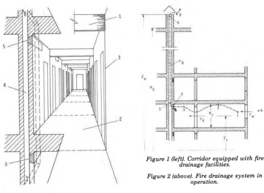
Figure 1 shows a corridor equipped with fire drainage facilities. These in- clude a series of retracted "fold-up curtains," 1, fastened to the ceiling at regular intervals. These curtains are made of metal strips mounted on ceramic cloth. Their purpose is twofold: to limit, while retracted, the spread of hot gases along the ceiling during the incipient phase of a fire in an adja- cent room, and to confine any fire that might penetrate the corridor after buildup in the fire room to a "corridor element,'' 2, formed after the two cur- tains on either side of the door of the fire rooms have been activated by heat or smoke. The two fold-up curtains slide down in grooves, 3, in the corridor walls. "Drainage ducts," 4, one for each corridor element, run vertically in the wall for the full height of the building. Under normal circumstances they are separated from the corridor by "entry gates", 5, located on one side of the corridor immediately below the ceiling. These gates are kept closed, usu- ally by a fusible device, until shortly after the release of two fold-up cur- tains. Deployment of any entry gate will trigger the opening of an "exit gate" (not shown, to be discussed later) installed at the top of each drainage duct (above the roof level).
With the opening of the entry and exit gates, the room on fire and the corridor element (formed by the released fold-up curtains) become connected
Figure I (teft). Corn'dor e uipped with fire drainage faciities.
Figure 2 (above). Fire drainage system in operation.
to the outside atmosphere above the roof level by means of the two gates and the drainage duct. Once the drainage duct has been filled with hot fire gases, a depression is created in the corridor element that will impede the spread of flames and smoke along the corridor. Figure 2 shows the fire drainage system in operation.
Clearly, operation of the fire drainage system blocks a section of cor- ridor. I t is only common sense, therefore, not to permit deadend corridors in buildings equipped with fire drainage facilities.
DESIGN PRINCIPLES
At first sight the design of the system may seem to be poorly defined. Owing to the randomness of a number of important factors, the severity of room fires is subject to considerable variation. As well, the formulation of the design problem depends a great deal on whether the door separating the fire room from the corridor is open or closed. With certain design assump- tions, however, these difficulties can be overcome:
1. That the temperature of fire gases, T, (K), is constant throughout the 1 system and higher than 373.2 K (100°C);
!
2. That the mass flow rate of the gases, U, (kg s-I), is essentially equal to ,
the mass flow rate of air entering the fire compartment, U, (kg s-'), ' and the density of fire gases, Q, (kg m-7, is essentially equal to that of
1
air at T,; 1
3. That the door of the fire cell is open and its windows (andlor the balcony door) have been destroyed by fire.
1
With respect to the first assumption, some of the input variables are ran- dom, so that the temperature of the fire gases cannot be estimated with any accuracy even for the room on fire. The gases cool as they pass through the corridor element and the drainage duct. Fortunately, as will be proved later, the design of the system depends only weakly on the value of T,. All in all, regarding the temperature of the fire gases as constant throughout the system and higher than about 100°C appears to be an acceptable assump- tion.As to the second assumption, it is known-hat the mass flow rate of fire gases is not more than 17 percent higher than the flow rate of the air enter- ing the fire room, so that
U,
'
U. is a fair approximation. Furthermore, since the fire gases consist predominantly of nitrogen, regarding them as essen- tially air a t a temperature T, is correct within a few percent tolerance.For the third assumption, that the door of the fire compartment is open and that its windows have been destroyed by fire, the design is expected to err on the safe side.
F i e Drainage 31 1. I t should keep the fire short and its severity relatively low.
2. I t should cause the combustion products originating from a fire in any of the rooms to be removed in an organized manner through the drainage ducts.
3. I t should keep the pressure in the corridor element (with the activa- tion of the fold-up curtains this will form part of the system) below the level of pressure in the adjacent corridor sections. This will prevent leakage of smoke into the rest of the building through either the cur- tains or gaps around them.
Fuel surface controlled (well ventilated) fires are knowd to be short and of low potential for destruction.' Requirement 1 is fulfilled if the designer ensures that the ventilation of the fire is high enough to bring about fuel surface controlled burning of fuel. Earlier indicated that for con- ventional furniture the condition for fuel surface controlled burning is
where G (kg) is fire load in the room, i.e., the mass of combustibles ex- pressed as calorifically equivalent mass of cellulosic fuel (0.005 is a dimen- sional constant; its dimension is s-I). If Equation 5 is satisfied, the duration of the fire will rarely exceed 1,200 s (20 min).
Requirement 2 concerns the dimensioning of the drainage ducts. The following information should be available to the designer:
G fire load in the room (kg);
G, cross-sectional area of all window openings (andlor balcony door) of the compartment (mZ);
Ad cross-sectional area of the door connecting the compartment with the corridor (m2);
al, a, tentatively selected dimensions of the (rectangular) drainage duct (m);
I
Hb
height of the building (m);H,
height of the room (and corridor) (m);I Z, elevation (above ground level) of the exit gates (m);
Z, elevation (above ground level) of the midheight of the floor con- sidered (m);
I
:
and, of course, the values fore,
ande,.
Using assumption 2 and the gas law, 'these densities can be calculated from the following equation:
where T
(K)
is temperature and 353.5 is a dimensional constant; its dimen- sion is kg K m-3.through the fire drainage system is usually negligible in the fire room and the corridor element. I t becomes significant only where the gases move through three constrictions: window openings, the doorway, and the drainage duct. The mass flow rate of the gases can be expressed in terms of ,
their velocities in these constrictions as follows:
where the
U,
'
U.
approximation has been used, and v,, vd, and VD (m s-') aregas velocities through the windows, doorway, and drainage duct, respec-
tively. I
The pressure distribution along the A-1-2-3-4-5-6'-6-B path of gas flow (Figure 2) will now be formulated. The Ap's (Pa) indicate pressure differences between two points (shown in the subscript) along the flow path. The varia- tion of pressure is associated partly with dynamic pressure losses and partly with static pressure differences. The pressure losses are expressed in terms of velocity heads. The velocity heads for gas flow through the drainage duct, doorway, and windows, VD, Vdr and V, (Pa), respectively, are as follows:
where T. (K) is the temperature of the outside air.
The loss for the flow of air across the windows (i.e., between points A and 1, Figure 2) consists of an entry and an exit loss; together they amount to approximately 1.5 velocity heads.
Between points 1 and 2 the gases heat up from T. to T,. The static pressure difference between points 1 and 2 is
The pressure loss for flow of gases across the doorway (between points 2 and 3) again amounts to 1.5 velocity heads.
Fire Drainage 33 An entry loss between points 3 and 4 amounts to a 0.5 velocity head.
Between points 4 and 5 the loss is due to the turbulence associated with entry of the gases into the vertical duct and to a change in flow direction. I t may be written as
where
fi
(dimensionless) is a factor with a value between 1.9 and 3.1, as willbe discussed later.
(fi
-
2.5 may be taken as an all-purpose design value.) The pressure difference between points 5 and 6 consists of two contribu- tions:a static pressure difference,
and a pressure loss due to frictional resistance of the drainage duct,
where f (dimensionless) is the friction factor for the drainage duct, and r (m) is the hydraulic radius of the duct. The expression for r is
To obtain f, one estimates the value of the surface roughness, E (m) for the
duct from Table 1, then calculates f by interpolation using Table 2.
I
Finally, the loss from fire gases leaving the exit gate (between points 6'
and B) amounts to 1 velocity head.I
TABLE 1. Surface r ~ u g h n e s s . ' ~ Surface c (m) Roueh brickwork -0.0075 ~ i v ~ e d steel 0.001-0.01 Concrete 0.0003-0.003 Cast iron -0.00025 Galvanized iron ~ 0 . 0 0 0 1 5 Wrought iron -0.00005The total pressure difference between points A and B along a path through the fire drainage system is obtained by totaling the pressure dif- ferences given in Equations 11 to 17 and 19. The result is
where a (dimensionless) is the pressure loss coefficient, introduced as a con- venient notation with the following meaning:
The total pressure difference between points A and B can also be ex- pressed along a path through the outside atmosphere:
After equating the right sides of Equations 20 and 22 and substituting for .
VD and Q, from Equations 8 and 6, respectively, the following expression is
1
derived for the velocity of gases in the drainage duct:
I
With this expression for VD the flow rate of gases, U,, is obtained
Ug
=
353.5 ADt/%
(Z
-
Zf)
a Tc,Tg2 (24)
in which Equations 6 and 7 have been used.
Examination of this equation reveals that U, has a maximum a t T, = 2T,. The variation of U,I(U,),., with T, for T, = 253.2 K (-20°C) is shown by the solid curve in Figure 3. I t may be seen that for a practical range of T,, U,I(U,),,
"
0.95, and therefore U, can be approximated asIn the light of Equation 5 the designer can now ascertain whether the condition of fuel surface control is fulfilled, i.e. whether the fire will be of short duration. If the designer finds that
U,
from Equation 25 is either less or much larger than 0.005 G , he should select new values for a, and a, (the dimensions for the fire drainage duct) and repeat the calculations.To complete the design, the designer should estimate whether the pressure in the corridor element at ceiling level (where the entry gate of the drainage duct is located), p,. (Pa), is lower than the pressure at the same level in the adjoining corridor sections, p, (Pa). According to Figure 2, p,.
Fire Drainage can be expressed as
After substituting from Equations 11 to 13, this can be rearranged in the form
where a' (dimensionless) is again a pressure loss coefficient for gas flow
through the windows and doorway, to be interpreted as
An expression for p, is obtained from Equation 4, with x = 0.9 and z =
Zf
+
Hr/2,The condition of no leakage is (p,, - p,)
<
0. Deducting Equation 29 from27, this condition can be expressed by the following:
1.1 I I I I I 1 . 0
-
A,---,,-- 0 o . B o o ern d-
-
-
3-
1'
E X P E R I M E N T A L P O I N T S-
0 . 5 - / T H E O R E T I C A L C U R V E S 0-l 3 I 0 . 4 - 1 0 S E R I E S I]
Ta = Ta = - 2 0 ° C-
I S E R I E S I I---
Ta = 1 5 ° C 0 . 3 - I-
I 0 . 2-
- 0 . 1 - - O 0 I I I I I 1 0 0 2 0 0 3 0 0 4 0 0 5 0 0 6 0 0 G A S I E M P E R A I U R E . f g . "CNeglecting the first term on the left side of the inequality (which results in an error on the safe side) and substituting from Equations 6,7, and 8, the condition of no leakage of gases to the adjoining corridor sections is ob- tained, after rearrangement, as
where
Ug*
(kg s-') is the required minimum air flow rate to achieve no leakage and T,(K)
is temperature in the heated interior of the building, usu- ally 293.2 K (20°C).Equation 31 is rather difficult to apply because of the random nature of two variables:
T,
andT,.
The designer may selectT,
in the 600 to 1,000K
range and
T.
in the 253.2 to 283.2 K (-20 to 10°C) range. If it is difficult to satisfy Equation 31, special measures (to be discussed Iater) may be taken to minimize the Ieakage of smoke through the curtain and through any gaps into the neighboring corridor sections.COMPONENTS OF THE FIRE DRAINAGE SYSTEM
The design of a few critical components of the fire drainage system will be discussed in this section, namely, the drainage ducts, the entry and exit
gates, and the fold-up curtains. In designing these components one should remember that fire is a very rare occurrence. Repair of components directly involved in fire need not be considered.
As to the drainage ducts, clearly they must be provided with sufficient insulation to prevent damage to building spaces adjacent to them. The re- quirements are very light, however. As the system is designed to cause the fire burn under fuel surface controlled conditions and the duration of fuel surface controlled fires is about 1,200 s (20 min), any noncombustible con- struction having a t least 30 min fire resistance is acceptable. For extra safety, it is recommended that the ducts be lined on the inside with a lightweight insulating blanket 2 to 3 cm thick. In order to reduce the fric- tional resistance this would present, a galvanized sheet steel cover may be applied over the insulation.
Entry and exit gates can be designed to be opened by the heat from the fire or, if an uninterrupted supply of electricity can be counted on, by smoke penetrating the corridor element. Only the first alternative will be discussed in this paper. The devices illustrated in Figure 4 have been selected to facilitate understanding of the operation;" they do not necessarily repre-
sent the best practical solutions.
In Figure 4 , l indim- the wall
of
the drainage duct and 2 the lining in-sulation. Each entry grtte. consists of two panels. 3 and 4, both attached to the gate frame, 5 , by hinges, 6, located near the lower inner edge of the frame. Insulation, 7, is added to the duct-side panel, 4, to protect the gate assembly from heat when the duct is filIed with hot gaseous products
F i e Drainage 37
originating from a fire on a floor
blow.
Both the duct-side and corridor-side panels are sealed to the frame. The duct-side seal, 8, must be made of rnoderateIy heat resistant material, whiIe the corridor-side seal, 9, can be any ordinary sealant.The
corridor-side panel is locked to the inside rimof
the frame by J - s h a d studs, 10, and nuts, 11, made of a low melting alIoy. The nuts are thermally insulated from the inner panel with washers, 12, possibly of a plastic material. A spring, 13, is compressed between the duct side and corridor side panels, which are connected by a short piece of wire rope, 14, that
will
prevent them from separating by more than a specified angle.Operation of the gate is fairly straightforward. As the fire builds up in the area, the fusible nut, 11, melts and causes the spring, 13, to open the corridor-side panel, which in turn pulls with it the duct-side panel via the wire rope, 14. Closed, the gates generally occupy a strip area 200 to 300 mm wide adjoining the ceiling. They may be concealed under wallpaper.
Gaseous products leave the fire drainage ducts through an exit gate
Figure 4. Fire drainage duct and entry and exit gates.
(Figuse 4) consisting of a frame, 15, and a doublewalled gate, 16, attached
to the frame by hinges, 17, and sealed to its rim by an ordinary sealant, 18.
The g ~ t e is
locked
in the frame by a small lever, 19, held in position by a U-shaped tongue, 20, and by the pulling force of a combustible rope or low melting wire, 21. If the pull ceases, a smalI spring, 22, removes the tongue from between the gate wall and the Ewer, thus allowing the lever to clear theframe. By its own weight the gate then falls down about its hinges. The pull on the rope or wire is provided by a weight, 23, hanging near the bottom of the duct. Pulleys, 24, transfer t h e pull to the U-shaped tongues.
Obviously, the unlocking of the exit gates must be precedd by the open-
ing of one entry gate along the drainage duct. The flames penetrating the duct then burn or melt away the rope or wire, 21. The fall of the weight, 23, causes the gate to open. A small door may be provided at the bottom of each
duct for cleaning and inspection. Ideally, the d u d gate system would be as-
sembled from prefabricated units.
Figure 5 shows a possible solution for the fold-up curtains.
The
curtainitself consists of a multitude of metal strips, 1, mounted on a ceramic cloth,
2. To the ends of every third or fourth strip. two studs, 3, are fastened that serve as axes for spherical rollers, 4, that are guided in vertical grooves, 5, when the curtain is deployed. Unfolding is initiated by a weightier bottom strip, 6. Even when completely unfolded, the curtain will retain a zig-zag pattern, to better resist the pressure difference between its two sides. (It is recommended that the whole curtain assembly, especially
a
strip area closeto the vertical edges, be treated with a n intumescent material to reduce, after deployment of the curtain, any infiltration of air into the corridor ele- ment through the ceramic cloth and the gaps along the vertical edges, or possibly the exfiltration of £ire gases if the depression in the corridor e l e ment is not sufficient.) The curtains are held in a folded position by a thin
Fire Drainage 39 metal strip, 7, interrupted on both sides by a fusible link, 8. Alternatively, the strip may be made from plastic that softens and releases the curtain at a desired temperature.
As mentioned earlier, all the critical components of the system can also be triggered by an electrical signal produced by heat or smoke sensors. To have the system activated by smoke detectors mounted in the corridors would offer some extra advantages. Even when the door of the fire room is closed, the activated system would function as a smoke shaft, preventing the spread of smoke along the corridors and to the upper stories of the building. In case the door burns through a t some advanced stage of the fire, the system would assume its principal function: to isolate the fire room from the rest of the building.
EXPERIMENTAL WORK
Experiments were conducted in a ten story building (1) to check the reliability of all components of the system, and (2) to obtain design informa- tion on its most critical component, the drainage duct.
The experimental corridor element was constructed on the third floor of the building (Figures 6 and 7). I t was formed by a 200 mm thick cinder block wall on one side, and the concrete wall of the building on the other. Both walls were covered with 25 mm thick Fiberfrax blanket to protect them from fire damage in the repeated experimental runs.
When retracted, the fold-up curtains were enclosed in a light steel sheet
a ,.
case, hinged a t the bottom and held closed by a metal strip. A fusible link, rated to melt at 90 to 95OC, was installed into the strip on both sides of the case.
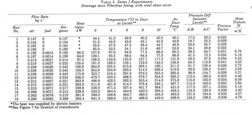
The corridor element was served by two drainage ducts fabricated from galvanized steel sheet and lined with 25 mm thick Fiberfrax blanket on the inside. The net cross-sectional area of the ducts was 300 by 150 mm. In one, the surface of the Fiberfrax lining was covered with steel sheet to reduce its frictional resistance to gas flow. Only one of the two ducts was in use in any one experiment.
The entry gates to the ducts were simple double-walled devices made from steel sheet and insulated with several Fiberfrax layers between the walls. The gates were hinged along the bottom edge, spring loaded on the duct side at the top, and secured in the closed position against the spring force with fusible pins, also rated to melt at 90 to 95°C. Because of their smaller surface areas, these pins melted and released the entry gates only after deployment of the two fold-up curtains. Two other entry gates iden- tical to those serving the corridor element were installed in the drainage ducts on the floor above to see whether they would stay reliabIy closed while the ~ystem was in operation as a result of a fire on the floor below.
The design of the two exit gates was, in the main, similar to that shown in Figure 4. Each was held closed by a weight hanging from a combustible string below the level of the entry gates.
Fire entering the corridor element from an adjacent room was simulated by two sand burners heated with propane gas.
y---q
THERMOCOUPLES1
/ / / / / / , p / l J J ' /
TABLE 3. Series I Experiments
Drainage duct: Fiberfrax lining, with steel sheet cover.
- -
(0
Flow Rate Pressure Diff
kg s" Temperature (OC) in Duct A v between Heat
Heat at Levels ** Duct L e ~ e l s * ~ Transm
R u n fire input Temp Friction
3
No. air fuel gases kW 3 4 6 8 10 "C A-B A-C Factor m2K
16 0.206 0.0071 0.213 328.6 532.0
17 0.202 0.0078 0.210 361.0 585.0
18 0.200 0.0085 0.208 393.4 641.3
*The heat was su by electric heaters
Several experiments were conducted to check the operation of the mov- ing parts and the correct sequence of the various phases of activation. In all of these the slide of the curtains was stopped 20 to 50 mm from the floor to allow air to enter the corridor element for the combustion of propane. There were no problems with the activation of the system. The two curtains always started the operation, sliding down in their grooves in quick succes- sion about 1 min after the start of the fire, when the temperature of the gases near the ceiling was about 140°C. Half a minute later the entry gate opened, and in another 10 sec, the exit gate. The entry gates on the floor above always remained reliably closed during these experiments.
The rest of the experiments were designed to study variables needed as input information in the design of the drainage ducts. To make the flow rate of gases in the drainage duct quantifiable, the fold-up curtains were r e placed by two steel sheet walls and air was introduced at a measured rate. To eliminate air leakage through the gaps around the steel sheet walls, the pressure difference between the corridor element and the surroundings was maintained as closely equal to zero as possible by appropriately adjusting the air flow rate. Pressure taps and thermocouples were located a t various heights along the corridor element and drainage ducts (Figure 7).
Two series of experiments were conducted, using one or the other duct (Tables 3 and 4). The sand burners were not used in the first few ex- I
periments of either series; the air pumped into the corridor element was i heated electrically, with the purpose of obtaining experimental points for the ascending section of the U,I(U,),, versus T, curve. Results are compared -
with theoretical prediction (dashed-line, Figure 3).
In Series I the Fiberfrax lining of the duct was covered with steel sheet to reduce frictional losses. The dynamic pressure losses were measured be- tween levels A-B and A-C (Figure 7). These values were used to determine the factor
fl
in Equation 15, and the friction factor, f. I t was found that 1.9<
fl
<
3.1, and thatfl
increased somewhat with the temperature of the fire gases. As Table 3 shows, the friction factor for the duct averaged 0.032. Ac- cording to Tables 1 and 2, this value of f corresponds to a surface roughness of about 0.0012 m, characteristic of riveted steel surfaces.Table 3 also gives information on the overall heat transfer through the wall of the duct, calculated using the formula
where h (W m-2K-1) is the coefficient of overall heat transmission through the duct, c (J kglK-') is the specific heat of the fire gases (air in essence; c
-
1030 J kglK-l), A, (m2) is the total of the inside surface area of the duct, T3 and Tlo (K) are temperatures at the bottom and top of the duct, respectively (i.e. between levels 3 and 10, see Figure 7). and To (K) is the temperature out- side the duct.Fire Drainage
r;
a
fire gases in the drainage duct is not an important piece of information as far as the design is concerned. Under real-world conditions, where walls are in all probability formed by masonry, the cooling of the fire gases is ex- pected to be less than that in the steel walled, Fiberfrax lined ducts used in these experiments.
Information on the Series I1 experiments is given in Table 4. In this series the insulating Fiberfrax formed the inside duct surface. The dynamic pressure loss was measured only between levels A and C (Figure 7). In calculating the friction factor it was assumed that the pressure loss between levels A and B was roughly the same as that in Series I. The friction factor averaged 0.072, which corresponds to a surface roughness of 0.01 m. I t is clear from the results of this series that a smooth duct surface is important for the satisfactory operation of the fire drainage system. According to the last column of Table 4, heat loss from the fire gases was considerably less than that in Series I. I t is assumed that the higher heat loss in the Series I experiments was due to heat conduction between the inside and outside steel sheets through some connecting elements.
EXAMPLE DESIGN
The task is to provide a 20 story office building with fire drainage facilities. The building has a uniform compartmentation pattern throughout its height. The rooms are, on the average, 20 m2 in area; they have two win- dows (total area 4.0 m2) and one door (area 2.0 m2) opening to the corridor. The height of the rooms is 2.4 m, the total height of the building is 53.0 m, and the elevation of the exit gate of the planned fire drainage system is 56.0 m.
As explained in the section Pressure Distribution in Buildings, equip- ping of the 10 lower stories with fire drainage facilities will only be con-
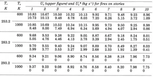
TABLE 5 . Results o f example calculations T, = 293.2 K.
T. T, U, (upper figure) and U,* (kg s-') for fires on stories
Fire Drainage
45
sidered. Statistical data indicate12 that the specific fire load in office buildings is about 25 kg m-2, so that the fire load in the office rooms is 20 X
25 = 500 kg. The condition of fuel surface controlled conditions is, accord- ing to Equation 5,
U. 2
0.005 X 500 = 2.5 kg s-'. The inside area of the drainage ducts is tentatively selected as 4.0 X 0.3 m.The operation of the fire drainage system will be examined in detail for the most adverse case: fire on the first floor during the winter heating season. The outside temperature is 253.2 K (-20°C); the temperature inside the building is 293.2 K (20°C). The temperature of the fire gases is assumed to be 600 K, which is about the lower end of the plausible range.
The input information can now be summarized as follows:
The hydraulic radius of the duct is (Equation 18):
The surface roughness of the ducts is taken (according to the experimental results) as 0.0012 m; thus ~ 1 4 r = 0.00215 and, from Table 2, f = 0.0243.
fl
(Equation 15) is assumed to be about 2.5. From Equation 21,From Equation 25,
From Equation 28,
I
I t may be seen that U, is much larger than the air flow rate necessary to
achieve fuel surface controlled condition (2.5 kg s-I). Yet, this high flow rate of air (or fire gases) is necessary to fulfill the U,
>
U,* condition, or in other words, to make it certain that there will be no leakage of gases from the cor- ridor element to be protected to the adjacent corridor sections.Table 5 gives the results of a complete set of calculations worked out for stories 1 to 10 and the following temperatures:
253.2 K (winter condition)
T.,
=(
283.2 K (yearly average) 293.2 K (summer condition)600
K
(cool fire)T8 = lo00
K
(hot fire).The values show that
1. The throughput (U,) of the system decreases only slightly with the level of the fire floor and outside temperature.
2. U, is practically unaffected by the temperature of the fire gases. 3. The possibility of leakage of fire gases from the comdor element to
the rest of the building (as characterized by U,*) is highest if fire breaks out on one of the first 3 floors during the winter heating season.
The designer may elect, in an effort to reduce the cost of the system, not to satisfy the U, 2 U,* requirement for these most adverse conditions, and to lessen the possibility of gas leakage to the unaffected areas of the
building by applying an intumescent coating to the fold-up curtains. I
Although the drainage ducts are installed on only one side of the cor- I
ridors, they serve rooms opening into the corridors from both sides. The loss of useful area with installation of a fire drainage system is usually 2 to 3 per- cent. I t may be less if the leakage problem under the most adverse condi- tions is only partially eliminated.
SUMMARY
I
Conventional fire protection practices are directed against hypothetical
fires assumed to spread through compartment boundaries. Real-world fires
usually spread by convection: by the advance of flames and hot fire gases. The fire drainage system arrests convective spread and confines the fire to the room of origin plus the small corridor element adjacent to it. The system may be designed in such a way that it does not rely on availability of water or electricity. If correctly designed and installed, it will ensure that any fire is of short duration and that the smoke does not leave the affected area.
Fire Drainage 47
NOMENCLATURE inside dimension of drainage duct, m.
area, cross-sectional area, m'.
elevation of neutral pressure plane, m. specific heat, J kg-'K-'.
friction factor, dimensionless.
P
avitational constant, m s-' ire load, kg.coefficient of overall heat transmission, W m"K-' height, m.
pressure, Pa.
E
ressure difference, Pa. ydraulic radius, m. temperature, K. mass flow rate, kg s-'. critical mass flow rate, kg s-'. velocity, m s-'.velocity head. Pa. elevation (variable), m. elevation, m.
pressure loss coefficient, dimensionless. surface roughness, m.
density, kg m-'.
factor, characteristic of a building space, dimensionless. Subscripts max 0 r s W of atmospheric air. of the building. for the corridor. for the corridor element. of, for, or through the doorway. of, for, or through the drainage duct. of the exit gate.
of the floor considered. of the fire ases. of the builfing interior. maximum
outside the drainage duct. of the room.
of the inside surface of the drainage duct. of, for, or through the window opening.
REFERENCES
' Yokoi, S., "A Method of Determining the Size of Vents", Building Engineering, Vol. 95,
pp. 46-52, 1959. Translation by National Research Council of Canada, Division of Building Research, TT 884, Ottawa, 1960.
' Thomas, P. H., Simrns, D: L., Hinkley, P. L., and Theobald, C. R., "Roof Venting of Burn- ing Enclosures, Part 111. Ventlng Fues of Constant Heat Output," JFRO. Fire Research Note No. 419. 1960.
' Landon-Thomas, G. J., and Hinkley, P. L., "Fire Venting in Single-Storey Buildings," JFRO, Fire Note No. 5, HMSO, London, 1965.
Guide for Smoke and Heat Venting, National Fire Protection Association, Quincy, MA, NO. 204M-1982.
Tamura, G. T., and Wilson, A. G., "Pressure Differences for a Nine-Storey Building a s a Result of Chimney Effect and Ventilation System Operation." ASHRAE Trans., Vol. 72, Part I, pp. 180-189, 1966.
Tamura. G. T., and Wilson, A. G., "Pressure Differences Caused by Chimney Effect in Three High Buildings," and "Building Pressures Caused by Chimney Action and Mechanical Ventilation." ASHRAE Trans.. Vol. 73. Part 11. 1967.
~ a r m a t h ~ , T. Z., " ~ e s i ~ n ' o f ~ u i l d i n ~ s for kire Safety," Fire Technology, Vol. 12, p. 95,
p. 219, 1976.
Harmathy, T. Z., "A New Look a t Compartment Fires," Fire Technology, Vol. 8, p. 196.
Harmathy, T. Z., "Some Overlooked Aspects of the Severity of Compartment Fires,"
Fire Safety Journal, Vol. 3. 261. 1981.
l o Streeter. V. L.. and ~ & e . E. B., FluidMechanics, McGraw-Hill Ryerson, Toronto, 1981.
p. 237.
" Harmathy, T. Z., "Means for Retarding the Spread of Fire from a Building Space," U.S.
Patent 3,955,323 (June 4, 1975), Can. Patent 1,009,889.(May 10, 1977).
" Pettersson, O., Magnusson, S. E.. and Thor, J.. "Fue Engmeermg Design of Steel Struc- tures," Swedish Institute of Steel Construction, Stockholm, Bulletin 50, 1976.
T h i s paper i s b e i n g d i s t r i b u t e d i n r e p r i n t form by t h e I n s t i t u t e f o r Research i n C o n s t r u c t i o n . A l i s t of b u i l d i n g p r a c t i c e and r e s e a r c h p u b l i c a t i o n s a v a i l a b l e from t h e I n s t i t u t e may be o b t a i n e d by w r i t i n g t o t h e P u b l i c a t i o n s S e c t i o n , I n s t i t u t e f o r Research i n C o n s t r u c t i o n , N a t i o n a l Research C o u n c i l o f C a n a d a , O t t a w a , O n t a r i o , KIA 0R6. Ce document e s t d i s t r i b u g s o u s forme de t i r e - 3 - p a r t p a r 1 ' I n s t i t u t de r e c h e r c h e e n c o n s t r u c t i o n . On p e u t o b t e n i r une l i s t e d e s p u b l i c a t i o n s de 1' I n s t i t u t p o r t a n t s u r les t e c h n i q u e s ou l e s r e c h e r c h e s e n matisre d e bdtiment e n d c r i v a n t 3 l a S e c t i o n d e s p u b l i c a t i o n s , I n s t i t u t d e r e c h e r c h e en c o n s t r u c t i o n , C o n s e i l n a t i o n a l d e r e c h e r c h e s du Canada, Ottawa ( O n t a r i o ) , KIA 0R6.