HAL Id: lirmm-00906202
https://hal-lirmm.ccsd.cnrs.fr/lirmm-00906202
Submitted on 19 Nov 2013
HAL is a multi-disciplinary open access
archive for the deposit and dissemination of
sci-entific research documents, whether they are
pub-lished or not. The documents may come from
teaching and research institutions in France or
abroad, or from public or private research centers.
L’archive ouverte pluridisciplinaire HAL, est
destinée au dépôt et à la diffusion de documents
scientifiques de niveau recherche, publiés ou non,
émanant des établissements d’enseignement et de
recherche français ou étrangers, des laboratoires
publics ou privés.
A Novel 4 DoFs (3T-1R) Parallel Manipulator with
Actuation Redundancy - Workspace Analysis
Samah Aref Shayya, Sébastien Krut, Olivier Company, Cédric Baradat,
François Pierrot
To cite this version:
Samah Aref Shayya, Sébastien Krut, Olivier Company, Cédric Baradat, François Pierrot. A Novel
4 DoFs (3T-1R) Parallel Manipulator with Actuation Redundancy - Workspace Analysis. MeTrApp:
Mechanisms, Transmissions and Applications, Oct 2013, Bilbao, Spain. pp.317-324,
�10.1007/978-94-007-7485-8_39�. �lirmm-00906202�
1
with Actuation Redundancy – Workspace
Analysis
Samah SHAYYA (a), Sébastien KRUT (b), Olivier COMPANY (b), Cédric
BARADAT (a), and François PIERROT(b)
(a)- TECNALIA FRANCE– MIBI Building, 672 Rue du Mas de Verchant, 34000 Montpellier, France- www.tecnalia.com
(b)-LIRMM –Université Montpellier 2 - 161 rue Ada, 34095 Montpellier, France E-mails: samah.shayya/[email protected]
krut/company/[email protected]
Abstract. This paper presents a novel 4 dofs (3T-1R1) parallel actuatedly redundant mechanism and
its workspace analysis, based on a performance index involving velocity and force capabilities. The ro-bot is capable of performing a half-turn2 about the z axis. Moreover, having all of its prismatic
tors along one direction; the x motion is independent- only limited by the stroke of the prismatic actua-tors. The mechanism is characterized by elevated dynamical capabilities having its actuators at base.
Key words: Parallel mechanism, actuation redundancy, 4 dofs mechanism, large rotational capacity, velocity and force performance index.
1 Introduction
For most industrial applications (such as machining) 6 dofs are too much. Thus studies have been conducted regarding the synthesis of 3 dofs (3T), 4 dofs (3T-1R) and 5 dofs (3T-2R) parallel manipulators. In fact, regarding some tasks, 4 dofs (3T-1R) parallel manipulators are sufficient. In others, where another rotation is required it can be provided either by the table or by an additional actuator in se-ries with the parallel mechanism. Many 3T-1R parallel manipulators exist in
1 3T-1R: Three-translational degrees of freedom (dofs) and one rotational
degree of freedom.
2 Samah SHAYYA, Sébastien KRUT, Olivier COMPANY, Cédric BARADAT, and François PIERROT
ature such as the famous Delta robot [2] (with the R-U-P-U 3 chain), the Kanuk
[10], the SMG in [1], the H4 in [8], the I4 in [6], the Par4 in [7] with its industrial-ized version Adept Quattro [9] (fastest industrial pick-and-place robot). Also, an interesting family of fully-isotropic parallel 4 dofs (3T-1R) manipulators, in addi-tion to decoupled manipulators, has been synthesized in [4]. In [4], there is an elaborated referencing to other 4 dofs manipulators.
However, these and other existing manipulators have some drawbacks. For ex-ample, in the case of Delta with a huge workspace (even much larger with linear Delta), the presence of the RUPU chain connecting the base to the platform to supply the rotational dof is a weak element reducing the workspace. Others pre-sent problems of singularities, limitation of workspace (and particularly) in rota-tional capability, complexity of obtaining analytical expressions for the direct ge-ometric model, and /or the use of transmission systems with the articulated platform as in the case [6-9] which impacts the accuracy of the robot. The manipu-lators in [4], despite their interesting isotropic property, have a limited workspace, are complex from manufacturability point of view, and have poor rigidity.
In this paper we present, a 4 dofs (3T-1R) parallel mechanism with two degrees of actuation redundancy that responds to the major requirements: large operational workspace, high rotational capability, absence of singularities, design simplicity, high rigidity, and high dynamical capabilities with analytical expressions for the inverse and direct geometric models. The paper introduces the mechanism in sec-tion 2, its geometrical elements, its inverse geometric model and the inverse jaco-bian matrix. Then section 3 describes the new performance index and workspace analysis of this mechanism. The paper ends with section 4 giving the conclusions.
2 The New 4 DoFs (3T-1R) Manipulator (ARROW)
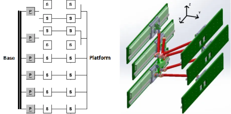
The graph diagram of the four dofs (3T-1R) parallel mechanism, called ARROW (Accurate Rapid Robot with Large Operational Workspace), is shown with its CAD drawing in Fig. 1. In Fig.2 we show the frontal view of the robot and platform details.
The robot consists of six actuators along the same direction (x-axis) and can perform four motions x, y, z and Θ (rotation about z-axis). The robot is redundant (having two extra actuators). It is quite clear that this robot can move along x in-dependently of the other motions y, z and Θ. This motion along x is only limited by the available stroke for the prismatic actuators. The role of parallelograms in
3 R, U, and P: correspond to rotational, universal, and prismatic joints. Bold
faced letter means actuated, and underlined letter means the joint position is measured.
chains (III) and (IV) (see Fig. 2) is to constraint the platform rotation about any axis that is perpendicular to the z axis of the base frame.
Fig. 1 Graph diagram of the mechanism on the left and CAD drawing of the robot with its base frame on the right. P: prismatic joint, S: spherical joint4. Gray box means actuated, while white
box means passive. The underlining signifies that the joint position is being measured.
These two parallelogram arms cooperate with the other four simple arms to po-sition the TCP and control the platform orientation about the z axis.
Let Li be the length of ith arm A Bi i (all simple arms are of equal length Ls
and parallelogram arms of equal length Lp) with Ai
qi yi zi
T and
Ti i i
i xb yb zb
B in the base frame. Note that
0
Ti i m m b b x z m i B in
plat-form frame and the terms yi and zi can be determined from Fig. 2. Denote
Tx y z
P (TCP coordinates) and the pose x
x y z
T ( : rota-tion about z-axis). Then the inverse geometric model (IGM) is given by:2 2 2 ( ( ) ) , 1...6 i i i b b b i i i i q x L y y z z i (1) cos( ) sin( ) 0 , with sin( ) cos( ) 0
0 0 1 m i i B P R B R (2)
4 Note that spherical joints practically can be replaced by three revolute joints
as to overcome the problem of limited angular deviations in commercial spherical joints.
4 Samah SHAYYA, Sébastien KRUT, Olivier COMPANY, Cédric BARADAT, and François PIERROT
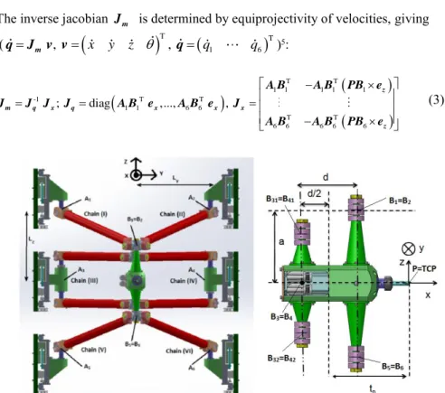
The inverse jacobian Jm is determined by equiprojectivity of velocities, giving
(
T
T 1 6 , x y z , q q m q J v v q )5:
T T 1 1 1 1 1 -1 T T 1 1 6 6 T T 6 6 6 6 6 ; diag ,..., , z m q x q x x x z A B A B PB e J J J J A B e A B e J A B A B PB e (3)Fig. 2 Frontal view of the robot on the left and platform details on the right (TCP at origin of base frame with zero rotation). The Ly and Lz are related to yi and zi coordinates of point Ai. Note that chains (III) and (IV) are parallelograms. The points A3 and B3 are along the virtual axis of parallelogram (III) (mid-line). The same applies for chain (IV). The TCP (tool center point) is
shown also and is denoted by P and it is the origin of the platform moving frame.
The singularity analysis (although is not discussed here in details due to space limitation) shows that if the mechanism is to have parallel type singularities they are necessary coincident with serial type singularities which cannot take place ex-cept at the boundary of the geometrically accessible workspace (when one of the arms happens to be in the yz plane provided that the corresponding pose is geo-metrically accessible). Hence, we can assure that there are no singularities of any type (serial or parallel) within the geometrically accessible workspace excluding its boundary.
5 Note that f df
dt
is the time derivative of a function f t( ). Note also that
x
3 Workspace Analysis
The workspace analysis can be limited to investigating the yz region that allows a half-turn (or a certain range of rotation) and where the value of the chosen perfor-mance index is within the acceptable range. There are several indices in literature that might be used to evaluate the robot’s performance [5, 11, 12] and each has its own limitations. However, in our case, we are interested in assuring a certain min-imal kinetostatic performance in all directions; more precisely assuring a minmin-imal speed capability while being capable at the same time of supporting a minimal ex-ternal force, regardless of the velocity or force direction. The robot under study being redundant, the singular values of the jacobian matrix are no longer signifi-cant regarding this aspect and so is the condition number based on the ratio of largest singular value to the minimal one. So, in our study and evaluation of the workspace, we have defined the following index:
min w , w wl wl v f FVI v f (4)
The terms vw and fw are the worst speed and the worst force respectively,
whereas vwl and fwlare the desired lower bounds for the worst speed and worst
force (not inducing internal stresses), respectively. Actually, vw is nothing except
the largest isotropic speed (radius of the largest sphere included in the zonotope of the operational velocities), and fw is similarly the largest isotropic force (radius of largest sphere included in the operational force zonotope not inducing internal stresses). In our case, we have chosen vwl0.25qmax and fwl0.25max. The terms qmaxand maxare respectively the maximum speed and maximum force of the linear actuator (all actuators are considered identical).
Since we have mixed dofs (translation and rotation), it is mandatory to homog-enize Jm before evaluating the index at each pose if we are interested in all dofs
(as to detect singularity while evaluating kinetostatic analysis)6. For this purpose,
we may use a suitable characteristic length... However, in our case, we are only in-terested in the translational dofs (x, y and z motions), so we will consider only the translational part ofJm, call it Jmp composed of the first three columns of Jm.
Note that this would not be sufficient unless a separate singularity analysis prior to this has been made and it is our case here (the study is not included here due to space limitation, but it is done). The terms vw and fw are given by:
6 Note that we can show that when 0 w
v , we have serial-type singularity and when fw 0 we have parallel-type singularity. So the closeness of FVI to zero can serve as a singularity measure as well.
6 Samah SHAYYA, Sébastien KRUT, Olivier COMPANY, Cédric BARADAT, and François PIERROT max 1...6 1...6 max 1 1 min , min || || w i || || w i v q f jmpri jpci (5) The terms i mpr j and i pc
j mean the ith row vector of matrix mp
J and ith column
vector of the matrix J , the pseudo-inverse of p Jmp. The proof of Eq. (5) is
simi-lar to the proof of the dynamic index introduced in [3].
In what follows we have established the yz region with zero orientation ( 0 ) and the yz region with rotation
45 45
despite the fact that the robot can produce half-turn (±45° being sufficient for our application) (see Fig. 3). Regarding the case of yz region with rotation, we have evaluated FVI for a set of different rotational angles particularly ±45°,±30° and 0° for the purpose of reduc-ing computation time and we assumed the worst value of this index for the corre-sponding ( , )y z position (in this case the minimal value of FVI). For this study, we used the following optimized parameters: Ls0.72m, Lp0.86m,0.35
y
L m, Lz 0.314m, d0.12m , a0.164m, and tp0.18m.
Notice that the robot has its workspace symmetric with respect to xz and yz planes, and convex. The latter property, namely convexity, is very advantageous regarding trajectory planning; any two points in the workspace can be connected by a straight line trajectory.
To avoid collision with slider guides, the TCP should be at least at a distance 0.2
l
t m in case of rotation ±45° and at a distance tw0.073m in case of zero rotation. Note that tw and tl are generally imposed by the platform dimensions,
spindle motor and tool size. These plots show that the yz region with and without orientation is large, especially when we consider the available space between its slider guides and collision limits with the sliders, which is quite interesting.
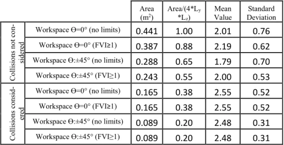
For better insight on the results regarding the workspace areas and variations of the index, we have tabulated them (see Table 1).
4 Conclusions and Future Work
In this paper, we have presented a new 4 dofs (3T-1R) parallel redundant mecha-nism (ARROW). It has 6 actuators for 4 dofs; the interest in this actuation redun-dancy is eliminating singularities and improving performance. The geometric models and inverse jacobian were derived. Singularity analysis results were briefed due to space limitation. We have then calculated the different workspaces and presented a new kinetostatic performance index “FVI” which is suitable for redundant and non-redundant robots equally well.
The workspace of this mechanism along x direction is independent of the other motions and only limited by the available stroke of the linear actuators, which is
one of its major advantages. The yz accessible regions are large in both cases with and without orientation, especially when compared to the space between its slider guides. The mechanism is particularly interesting having the capability to perform a half-turn (complete rotation is not possible due to unavoidable collisions).
Fig. 3 Accessible yz regions for ϴ=0° (left) and for ϴ between -45° and +45° (right): quarter of the region is shown since it is symmetric with respect to y-axis and z-axis. The red solid lines show the boundaries that should not be exceeded by the TCP to avoid collisions with the sliders
(vertical red line) and inter-arm collisions (horizontal red lines).. Dotted black line shows the available space within the linear sliders.
Table 1: Workspace analysis and FVI index variations over the workspace. Area (m2) Area/(4*L*L y z) Mean Value Standard Deviation C ol lis io ns n ot c on-si de re d
Workspace ϴ=0° (no limits)
0.441
1.00
2.01
0.76
Workspace ϴ=0° (FVI≥1)0.387
0.88
2.19
0.62
Workspace ϴ:±45° (no limits)0.288
0.65
1.79
0.70
Workspace ϴ:±45° (FVI≥1)0.243
0.55
2.00
0.53
C ol lis io ns c on si d-er edWorkspace ϴ=0° (no limits)
0.165
0.38
2.55
0.52
Workspace ϴ=0° (FVI≥1)0.165
0.38
2.55
0.52
Workspace ϴ:±45° (no limits)0.089
0.20
2.48
0.31
Workspace ϴ:±45° (FVI≥1)0.089
0.20
2.48
0.31
Besides, having the arms connected to the platform and actuators via spherical joints, puts these arms under tension/compression forces making it easier to model deformation and compensate for it. In brief the simplicity of the design, the actua-tion redundancy, the actuaactua-tion at base, and the high stiffness of the mechanism8 Samah SHAYYA, Sébastien KRUT, Olivier COMPANY, Cédric BARADAT, and François PIERROT
contribute to the high dynamical capabilities (regarding pay-load, acceleration and velocity) as well as to its enhanced performance regarding accuracy. Regarding the future work, the introduced robot is currently being under further study (re-garding dynamics) and under optimization in the sense of implementing it and producing a prototype on which real performance can be evaluated.
Acknowledgement
This work has been supported partially by the French National Research Agency within the ARROW project (ANR 2011 BS3 006 01) and by Tecnalia France.
References
1. Angeles J., Caro S., Khan W., Morozov A., « The kinetostatic design of an innovative Schonflies-motion generator », Proceedings of the Institution of Mechanical Engineers, Part C: Journal of Mechanical Engineering Science 220 (7) (2006) 935–943.
2. Clavel R., “Une nouvelle structure de manipulateur parallèle pour la robotique légère », APII, 23(6), 1985, pp. 371-386.
3. Corbel D., Gouttefarde M., Company O., and Pierrot F., “Towards 100G with PKM. Is actuation redundancy a good solution for pick-and-place?” 2010 IEEE International Conference on Robotics and Automation, Anchorage, Alaska, USA, May 3-8, 2010. 4. Gogu G., “Structural synthesis of fully-isotropic parallel robots with Schonflies motions via
theory of linear transformations and evolutionary morphology”, European Journal of Mechanics A/Solids 26 (2007) 242-269.
5. Gosselin C. and Angeles J., “Global performance index for the kinematic optimization of robotic manipulators”, Transaction of the ASME, Journal of Mechanical Design, Vol. 113, no. 3, pp. 220-226, 1991.
6. Krut S., Company O., Benoit M., Ota H., and Pierrot F., “I4: A new parallel mechanism for Scara motions,” in Proc. of the 2003 Int. Conf. on Robotics and Automation, Taipei, Taiwan, September 2003, pp. 1875–1880.
7. Nabat V., Company O., Krut S., Rodriguez M., and Pierrot F., “Par4: very high speed parallel robot for pick-and-place”, in Proc. IEEE International Conference on Intelligent Robots and Systems (IROS’05), Edmonton, Alberta, Canada, August 2005.
8. Pierrot F., Company O., H4: a new family of 4-dof parallel robots, In: Proc. of the IEEE/ASME Int. Conf. on Advanced Intelligent Mechatronics, Atlanta, USA, 1999, pp. 508–513.
9. Pierrot F., Nabat V., Company O., Krut S., “From Par4 to Adept Quattro”, in Proc. Robotic Systems for Handling and Assembly - 3rd International Colloquium of the Collaborative Research Center SFB 562, Braunschweig, Germany, (2008).
10. Rolland L., “The Manta and the Kanuk: Novel 4 dof parallel mechanism for industrial handling”, in Proc. of ASME Dynamic Systems and Control Division IMECE’99 Conference, Nashville, USA, November 14-19, 1999, vol. 67, pp. 831-844.
11. Salisbury J. K. and Craig J. J., “Articulated hands: force control and kinematic issues”, International Journal of Robotics Research, Vol. 1, no. 1, pp. 4-17, 1982.
12. Yoshikawa T., “Manipulability of robotic manipulators”, International Journal of Robotics Research, Vol. 4, no. 2, pp. 3-9, 1985.