Publisher’s version / Version de l'éditeur:
Journal of Applied Polymer Science, 28, 3, pp. 1033-1044, 1983-03
READ THESE TERMS AND CONDITIONS CAREFULLY BEFORE USING THIS WEBSITE.
https://nrc-publications.canada.ca/eng/copyright
Vous avez des questions? Nous pouvons vous aider. Pour communiquer directement avec un auteur, consultez la
première page de la revue dans laquelle son article a été publié afin de trouver ses coordonnées. Si vous n’arrivez pas à les repérer, communiquez avec nous à [email protected].
Questions? Contact the NRC Publications Archive team at
[email protected]. If you wish to email the authors directly, please see the first page of the publication for their contact information.
NRC Publications Archive
Archives des publications du CNRC
This publication could be one of several versions: author’s original, accepted manuscript or the publisher’s version. / La version de cette publication peut être l’une des suivantes : la version prépublication de l’auteur, la version acceptée du manuscrit ou la version de l’éditeur.
Access and use of this website and the material on it are subject to the Terms and Conditions set forth at
Morphology of polyurethane modified by plasticizing, blending, or
reinforcing
Blaga, A.; Feldman, D.
https://publications-cnrc.canada.ca/fra/droits
L’accès à ce site Web et l’utilisation de son contenu sont assujettis aux conditions présentées dans le site LISEZ CES CONDITIONS ATTENTIVEMENT AVANT D’UTILISER CE SITE WEB.
NRC Publications Record / Notice d'Archives des publications de CNRC:
https://nrc-publications.canada.ca/eng/view/object/?id=4ea3330b-06cd-4789-bdab-5075d1ed2a40 https://publications-cnrc.canada.ca/fra/voir/objet/?id=4ea3330b-06cd-4789-bdab-5075d1ed2a403er
National Research
Conseil national
rHl
'
Council Camda
de recherches Canada
N21d
MORPHOLOGY OF POLYURETHANE MODIFIED BY PLASTICIZING, BLENDING, OR REINFORCING
by A. Blaga and D. Feldman
ANALYZER
Reprinted from
Journal of Applied Polymer Science Vol. 28,1983, p. 1033
-
1044DBR Paper No. 1097
Division of Building Research
Price $1.25 OTTAWA
W.
RES.
La morphologie d ' u n p o l y u r 6 t h a n e t h e r m o p l a s t i q u e m o d i f i s a 6 t 6 CtudiCe p a r m i c r o s c o p i e 6 l e c t r o n i q u e b b a l a y a g e e t p a r c a l o r i m 6 t r i e d i f f g r e n t i e l l e b b a l a y a g e . Le p o l y u r 6 t h a n e a 6 t 6 m o d i f i 6 p a r a d d i t i o n d e d i f f 6 r e n t e s q u a n t i t E s de p h t a l a t e de d i b u t y l e (DBP), un p l a s t i f i a n t , de polymeres v i n y l i q u e s (PVA, PVAc, PVC, copolymere VAc-VC), d e p o l y s i l o x a n e ou de f i b r e s ( d e v e r r r ou d e c o t o n ) b un d i o l p o l y C t h e r , p u i s il a 6 t 6 mElangE b d u diph6nylmGthane-diisocyanate e t a g i t 6 vigoureusement. L'examen a u microscope G l e c t r o n i q u e b b a l a y a g e a rEvEl6 que l e p o l y u r 6 t h a n e e t l e p r o d u i t m o d i f i s p r g s e n t a i e n t une s t r u c t u r e c e l l u l a i r e (mousse). On a o b s e r v 6 u n e m a t r i c e homogene d a n s l e s mslanges b i n a i r e s p o l y u r S t h a n e - p h t a l a t e d e d i b u t y l e pour d e s r a p p o r t s a l l a n t d e 2 0 : l 5 6,6:1; d a n s l e s m6langes a v e c l e PVA, l e PVAc e t l e copolymere VAc-VC d a n s un r a p p o r t massique de 4 0 : l ; e t d a n s l e p o l y u r g t h a n e r e n f e r m a n t d e s f i b r e s de v e r r e ( 2 0 : l ) ou d e s f i b r e s de c o t o n ( 4 0 : l ) . On a confirm6 l a m i s c i b i l i t 6 d e s c o n s t i t u a n t s d e s m6langes p o l y u r 6 t h a n e - p h t a l a t e de d i b u t y l e p a r c a l o r i m e ' t r i e d i f f g r e n t i e l l e B b a l a y a g e , mais c e t t e mgthode n ' a p a s permis d f 6 v a l u e r l a m i s c i b i l i t 6 d e s c o n s t i t u a n t s d a n s l e s a u t r e s m6langes b i n a i r e s . Les d l a n g e s PU-PVA ( r a p p o r t m a s s i q u e 20: 1 )
,
PU-PVC ( r a p p o r t m a s s i q u e 20: 1 b 5: 1 ) ou PU-polysiloxane G t a i e n t hgtCrogCnes, donc non m i s c i b l e s , c o r n l ' i n d i q u a i e n :l e s r C s u l t a t s de l'examen a u microscope g l e c t r o n i q u e . A l ' e x c e p t i o n d e s m6langes PU-PSO, l e comportement t h e r m i q u e d e s mglanges h 6 t 6 r o g S n e s ne permet p a s de t i r e r de c o n c l u s i o n q u a n t 2 l a m i s c i b i l i t g .
Morphology of Polyurethane Modified
by Plasticizing,
Blending, or Reinforcing
A. BLAGA, Division of Building Research, National Research Council of Canada, Ottawa, Canada K I A 0R6, and D. FELDMAN, Centre for Building
Studies, Concordia University, Montreal, Canada
Synopsis
The morphology of modified thermoplastic PU has been studied by SEM and DSC. The PU was modified by addition of various amounts of dibutyl phthalate (DBP) plasticizer, vinyl polymers (PVA, PVAc, PVC, VAc-VC copolymer), polysiloxane or fiber reinforcement (glass or cotton) to diolpo- lyether, followed by mixing and vigorous stirring with dephenylmethane diisocyanate. SEM oh- servations indicated that PU and its modi."ications have a cellular (foam) structure. A homogeneous matrix was observed in binary blends of PU and DBP in ratios of 20:l down to 6.6:l; PVA, PVAc, VAc-VC copolymer with a weight ratio of 40:1, PU containing glass fiber (20:l) or cotton fiber (40:l). Blends of PU-with PVA at a weight ratio of 20:1, with PVC in ratios from 20:l down to 5:1, or with polysiloxane polymer-were heterogeneous and thus not miscible, as evidenced by SEM observations. With the exception of the PU-PSO mixtures, the thermal behavior of the heterogeneous blends did not permit any conclusion regarding miscibility.
INTRODUCTION
The usefulness of polymers can be considerably increased by physical blending. By careful selection of two or more polymers in certain proportions it is often possible to achieve in the end product (polymer blend) more desirable properties than those inherent in the components. Specific properties such as mechanical, electrical, or thermal properties may be modified by blending polymers or by mixing them with special additives, for example, plasticizers and reinforcing agents.
Commercial polymer blends are numerous and are used in a wide range of app1ications.l They are based on either miscible polymers such as those used in polystyrene-poly(pheny1ene oxide) and PVC-nitrile rubber products or on immiscible polymers such as those in rubber blends in tires or the well-known impact-modified plastics.2
For many purposes miscibility in polymer blends is neither required nor de- ~ i r a b l e . ~ Most commercial blends consist of mixtures of two polymers, the majority of them not miscible, with the result that the blends are heterogeneous. Phase morphology and adhesion are therefore more important considerations in polymer blend technology since they critically influence many properties and subsequent uses of the end product.
Because of their good chemical and physical characteristics, including excellent abrasion resistance, polyurethanes (PU) and derived blends are used in various applications as foams, plastics, adhesives, elastomers, and coating^.^^^ The good properties of these materials are exhibited throughout the moderate temperature
Journal of Applied Polymer Science, Vol. 28,1033-1044 (1983)
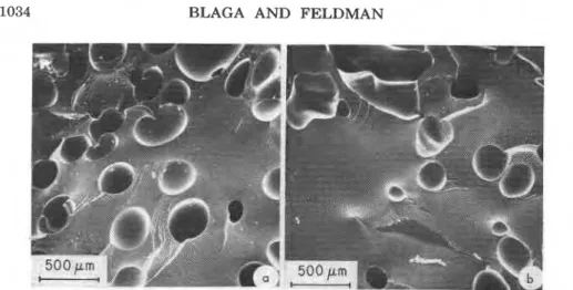
Fig. 1. SEM photomicrograph of fracture surface: (a) unblended PU; (b) PU-DBP (ratio of 1o:l).
range and in oil and oxidative atmospheres. They are not outstanding a t high temperature nor in atmospheres where hydrolytic action may be strong. The elevated temperature resistance depends upon service conditions and the type of polymer used.3 Many studies have been conducted on blends of polyurethane with polybutadieneY5 polyacrylamide,6 and poly(viny1 ~ h l o r i d e ) ~ , ~ and other
thermoplastic^,^ but most have dealt with theoretical aspects of blends. Re- corded results on morphology of blends prepared by practical methods are still scarce.
The work now reported is part of a study of P U blends prepared by adding a plasticizer, thermoplastic polymer or a reinforcement to one of the liquid reac- tants (the polyol) used subsequently to produce polyurethane. Previous papers described results of work on mechanical and adhesive properties and on the weathering resistance of some of these blends to artificial and natural expo- ~ u r e . ~ - l l This paper reports results of a study by scanning electron microscope (SEM) and differential scanning calorimetry
(DSC)
techniques of the mor- phology ofPU
modified by plasticization, blending with thermoplastic polymers, or reinforcing with fibers.I'
Fig. 2. PU-PVA (ratio of 20:l).MORPHOLOGY OF POLYURETHANE 1035
Fig. 3. (a) and (b) PU-PVA (ratio of 20:l).
EXPERIMENT Materials
In all blends a two-component, adhesive-grade PU formulation supplied by Reichhold Chemicals (Canada) Ltd. was used, the main reactants consisting of I
1 a diol polyether and diphenylmethane diisocyanate (MDI) in a 1:l weight ratio.
I
The other materials were also commercial grades, as follows: poly(viny1 chloride)(PVC,
103E-FF-7 Resin, B. F. Goodrich); poly(viny1 acetate) (PVAc, Mowillith 30, Hoechst) ; poly(viny1 alcohol) (PVA, Anachemia); vinyl acetatRviny1 chloride copolymer (VAc-VC Copolymer,
Hostaflex
M
131, Hoechst) ; polysiloxane(PSO,
Silpruf, General Electric Co.); glass fibers with a length distribution in the range of 10to
15 mm; cellulose fibers with a length distribution in the range of 20-25 mm; dibutyl phthalate (DBP, Anachemia). The composition of the mixtures is given as weight ratios of PU to the added material.To prepare the blends, the appropriate amounts of plasticizer, polymer, or reinforcing fibers were added to the diol polyether, then mixed with the MDI to form the PU. Vigorous stirring ensured good mixing.
I
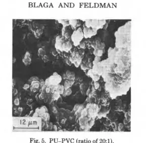
1036 BLAGA AND FELDMANFig. 5. PU-PVC (ratio of 20:l). Apparatus and Procedures
Fracture surfaces of the various samples were observed with a Cambridge Stereoscan Mark IIA SEM operated at 20 kV and tilt angle of 45 deg. The fracture surfaces were obtained by using a chisel and hammer to split samples cooled at the liquid nitrogen temperature. This technique was found to provide the most satisfactory fracture surface for observation and for drawing conclusions about the bulk. The specimens were coated first with carbon and then with gold to prevent electrical charging.
The DSC curves were recorded with a DuPont 1090 thermal analyzer over a temperature range of -110 to 240°C at a heating rate of 20°C/min under nitrogen, but thermal behavior outside the -80 to 120°C range was of no consequence for the present discussion. Only portions of the DSC curves corresponding to the narrower range will therefore be discussed.
RESULTS AND DISCUSSION
Typical microscopic structures of samples of modified PU are illustrated by the SEM photomicrographs presented in Figures 1-9. SEM observations on
MORPHOLOGY OF POLYURETHANE 1037
Fig. 7. (a) and (b) PU-polysiloxane (ratio of 1:2).
the various samples are summarized in Table I. The fracture surface of each sample of PU modified by plasticizing, blending, or reinforcement was examined at magnifications of up to 100,000. With only a few exceptions the magnifica- tions of the photomicrographs range between 30 and 350. DSC curves are shown in Figures 10 and 11, and the thermal transitions are listed in Table 11.
Dibutyl Phthalate (DBP)-Modified Polyurethane (PU)
SEM examination of fracture surfaces indicated that addition of DBP to the PU formulation results in blends with a single, homogeneous solid phase. In Figure 1 the fracture surface of unblended PU is compared with that of a PU- DBP blend having a 10:l weight ratio. The surface of the unblended PU [Fig. l(a)] has portions of smooth areas and variously shaded, approximately circular depressions resulting from the fracture of the cells (voids). Thus the polyure- thane has a cellular (foam) structure caused by the formation of COa bubbles due to traces of water, and the matrix (solid phase) is homogeneous a t magnifi- cations up to 100,000.
The appearance of the fracture surface of PU-DBP blends is very similar to that of unblended PU, the solid material consisting of a single phase. The
Fig. 9. (a) and (b) PU reinforced with cellulose fibers (ratio of 40:l).
PU-DBP blends also have a foam structure, but the number of cells per unit volume is smaller than the number in the unblended PU [Fig. l(b)] and generally decreases with increasing DBP content. Thus, PU and DBP are miscible in the concentrations used in this study, like the well-known PVC-DBP system.
In Figure 10, the DSC curve of unblended PU is compared with curves for the PU-DBP blends. The thermal behavior of thermoplastic polyurethane polymer has already been studied.12-l4 Because of its complex molecular structure the DSC of PU polymers generally has several thermal transitions.12 Thermoplastic P U polymers consist of blocks or segments of two dissimilar repeat units along the molecular chain backbone and are called block or segmented copolymers. At service temperature one of the block components (the soft segments), usually a polyether or polyester chain, is rubbery; the other is glassy or crystalline in nature (the hard segments), consisting of polyurethane chain segments. Most of the segmented copolymers exhibit a two-phase microstructure (with hetero- geneity on the segmental level) due to the immiscibility of the two dissimilar segments.12 The heterogeneity due to segmental immiscibility could not be detected by SEM. Generally, thermal transitions in thermoplastic polyurethane occur in five temperature ranges.12 Important transitions found in most ther- moplastic polyurethanes include glass transition of the soft segment, Tgs, between -80°C and -10°C; microcrystalline melting of the soft segments, T,,, between 10°C and 20°C; endotherm associated with the dissociation of short-range, or- dered, hard segment domains, Tdh, (30-60°C); microcrystalline melting of hard-segment domains, Tmh, (130-200°C). Although a glass transition of hard-segments (Tgh) should occur, it is not always detected.12J4
The thermal transitions detected by DSC measurements in the unblended PU occurred a t -46°C (T,,), 12°C (T,,), 60°C (Tdh), and 219°C (Tmh) (not shown). The endotherm of the glass transition of the soft segments (Tgs) in PU and PU-DBP blends was very broad and of low intensity. The effect on T,, of adding DBP to PU could not be determined, therefore. The glass transition of the hard segments was not observed in the DSC curves. Addition of DBP plasticizer to the PU formulation, however, induced changes in two of the en- dotherms of the DSC curve of the resulting blends (Fig. 10). The endotherm a t 12"C, resulting from crystalline melting of the soft segment domains in the
TABLE I
Results of SEM Observations of Fracture Surfaces of Modified Polyurethanea Weight
Sample ratio Observations Sample Weight Observations
PU - Matrix homogeneous; relatively small PU-PVC 40:l' Two-phase matrix, PVC component dispersed as
number of c a b particles of
PU-DBP 20:l Matrix homogeneous; smaller number of PU-PVC 20:l varying s i r ~ s emhedded in
I
PU-DBP 1O:l cells than in unblended PU-PVCb 20:l wallsand
E
struts; particles 0
PU, decreasing with DRP
PU-DBP 6.6:l con tent PU-PVC 10:l consiab of
agreggates of
x
PU-PVA 40:l Matrix homogeneous; PU-PVC 1 ; approximately
P
very l a x e number of spherical 0 0
close-packed cells granulm 4
PU-PVA 20:l Matrix in two phases; PU-PSO 2:l' Two-phase matrix;
many large cella cell wall
thickness 'd
PU-PVAc 40: 1 Matrix homogeneous; PU-PSOC 2:l increasing with
many large cells I PSO content,
P
4with very thin but, number of cells C
PU-(VAc-VC) 40:l walls (membranes) PU-PSO 1:l cells larger
than in PU 4
PU-PSO 1:2 /
PU-GFd 20:l Homogeneous matrix; weak
E
adhwion of matrix to
3
glass fibrea
PU-CFd 40:l Homogeneous matrix; cotton fibers segregated and located excluaively in surface layer~
a All samples have a cellular (foam) structure. In blends with heterogeneous matrix, the adhesion between polymer components was good. b Slow mixing waq used during preparation.
This sample contained a small amount of carbon black. d GF and CF designate glass fiber and cotton fiber, respectively.
0 I- a Y - 2 0 - - 2 4 - 2 8 -32
-
-
-
-
1 n 1 r 1 4 i o - 8 0 -40 0 40 80 120 TEMPERATURE, 'CFig. 10. DSC curves of polyurethane (PU) and polyurethane-dibutyl phthalate (DBP) blends: (A) PU; (B) PU-DBP (20:l); (C) PU-DBP (10:l); (D) PU-DBP (6.6:l).
unblended PU, decreased in intensity so that its onset temperature (T,,) was
shifted to a lower value with increasing DBP content of the blends (Table 11).
At a weight ratio of 6.6:l the
T,,
was only 1°C. Similarly, the onset temperature 1of the higher endotherm at 60°C in the unblended PU was lowered to approxi-
I I I I l I I 1 I
d
- 3 2 - L ' 1 n 1 4 . - 8 0 - 4 0 0 40 80 120
TEMPERATURE. " C
Fig. 11. DSC curves of polyurethane (PU), polysiloxane (PSO), and PU-PSO blends: (A) PU; (B) PU-PSO (2:l); (C) PU-PSO (1:l); (D) PU-PSO (1:2); (E) PSO.
I
MORPHOLOGY OF POLYURETHANE 1041
TABLE I1
Thermal Transitions of Polymer Blends and Blend Components
Thermal Thermal Thermal
Weight transitions Weight transitions Weight transitions
Sample ratio (OC) Sample ratio (OC) Sample ratio (OC)
PU" - 12; 60 PU-PVC 40:l 9; 60 PU-GFd
-
12; 60PU-DBP 20:l 3; 60 PU-PVC 20:lb 8; 60 PU-CFd
-
12; 60PU-DBP 10:l 7; 56 PU-PVC 20:l 15; 60 PVA - 11; 48
PU-DBP 6.61 1; 20 PU-PVC 1O:l 7; 61 PVAc 11; 50
PU-PVA 40:l 12; 60 PU-PVC 5:l 8; 60 VAc-VC
-
9; 30; 73copolym.
PU-PVA 20:l 18; 60 PU-PSO 2:l -42; 9; 60 PVC - 9; 86
PU-PVAc 40:l 8; 32 PU-PSO 2:lc -42; 9; 57 PSO - -42; 2(sh)
PU-(VAc-VC) 40:l 9; 60 PU-PSO 1:l -42;9; 57
PU-PSO 1:2 -42; 8; 56
a The T,, (glass transition temperature of soft segment) at -45OC was not affected by plasticization,
blending, or reinforcing; the transition at 12OC is due to crystalline melting of soft segments and that a t 60°C is associated with breakup of short-range ordered hard segment.
Slow mixing was used during preparation.
This sample contained a small amount of carbon black.
GI? and CF designate glass fiber and cotton fiber, respectively.
mately 20°C in the same PU-DBP blend. These changes can be interpreted in the following manner. When compatible nonpolymeric plasticizers or solvents are added to polymers, they are attracted to portions of the molecules and pen- etrate between adjacent molecular chains. This causes less well-ordered mo- lecular structures less able to fit in a crystalline lattice, resulting in reduced crystallinity and thus a lower crystalline melting point.15 Because in these blends the T,, is lowered to a greater extent than the Tdh, it is suggested that DBP has a greater affinity for the soft segment material and mixes with it before any significant mixing occurs in the hard segment regions. This induces an increase in the size and a lowering of the temperature of the corresponding endotherm (Fig. 10).
Blends of Polyurethane with Vinyl Polymers
Binary blends of PU were prepared with poly(viny1 alcohol) (PVA), poly(viny1 acetate) (PVAc), vinyl acetate-vinyl chloride (VAc-VC) copolymer, and poly- (vinyl chloride) (PVC). Observation by SEM of the fracture surfaces revealed that, like the PU-DBP blends, these materials have a cellular structure. The matrix is homogeneous in blends of PU-PVA, PU-PVAc, and PU-(VAc-VC) copolymer with a 40:l weight ratio, but it is heterogeneous in PU-PVA with a
20:l ratio and in all the PU-PVC blends (Table I). An illustration of the surface structure of the blends with homogeneous matrices is provided by the SEM photomicrograph in Figure 2. The surface structure indicates that the blend
!
consists of a large number of close-packed cells and a single phase matrix; thecell walls (membranes) are thinner than those of the unblended PU. In the
I PU-PVA blend with a 20:l ratio phase separation in the matrix was detected
at relatively lowhagnification [Fig. 3(a)]. The particles of PVA vary in size and are irregular in shape [Fig. 3(b)]. Furthermore, the cell size is larger than in the
40:l PU-PVA blend (with a homogeneous matrix) and considerably larger than that in the unblended PU [Fig. l(a)].
In PU-PVC blends PVC is present (in the matrix) in the form of a dispersed particulate phase, as is illustrated by the SEM photomicrographs in Figure 4. The PVC particles are embedded in the cell membrane and struts. Examination at higher magnifications indicates that each particle consists of an aggregate of small, approximately spherical granules (Fig. 5). Similar morphologies were present in all blends. Thus, mixing of PU and PVC homopolymer in weight ratios from 20:l down to 5:l results in cellular blends with non-homogeneous matrices, i.e., PU and PVC are immiscible. The SEM examination also revealed that adhesion between PVC particles and the PU matrix is good. It is known that good adhesion between the components of a blend is important because it determines the mechanical properties.2
The DSC curves of all these blends could not be used to determine the misci- bility of the polymer components. In fact, the two pertinent transitions of the vinyl polymers and the unblended PU occurred within a relatively narrow tem- perature range (Table 11). The changes induced in these endotherms by blending are therefore complicated by overlapping.
Polyurethane-Polysiloxane Blends
The SEM photomicrographs of fractured surfaces of PU-PSO blends with composition ratios of 2:l and 1:2 are shown in Figures 6 and 7, respectively. The blend with the higher composition ratio yields a foamed material with larger cells and thinner walls than those in the blend of lower ratio. In the former, the polysiloxane phase is detectable as particles of varying size and shape. The fractured surface of the particles is very rough, in contrast with the smooth ap- pearance of the PU phase [Fig. l(a)]. The blend with the higher polysiloxane content (lower PU-PSO ratio) yields a foam with smaller cells and thicker walls and struts than those in blends of lower polysiloxane content. The polysiloxane polymer becomes the continuous phase and exhibits, again, a rough surface; the PU phase has a smooth appearance. Addition of 1% carbon black to a blend of PU-polysiloxane (2:l ratio) did not affect the morphology of the resulting blend.
Similar morphology was observed in PU-PSO with a 1:l ratio. Thus, SEM observations indicate that PU and PSO are essentially not miscible. In all the PU-PSO blends good adhesion of the components was observed.
Normally, blends of immiscible polymers that segregate into distinct phases exhibit glass transitions identical in temperature and width to those of the un- blended components.16 In the DSC curves of PU-PSO blends there is a sharp endotherm having the same onset temperature (-42OC) and peak half-width as those of the unblended PSO component (Fig. 11 and Table 11). The un- blended PU has a low-intensity, very broad endotherm assigned to the glass transition of the soft segments
(T,,)
at -450C.12 The low intensity of this en- dotherm and the overlapping temperature range of the transitions does not permit an inference on the partial miscibility of the PSO component with the soft segments of the PU. The next transition, T,,, in PU is also in the same temperature range as a minor thermal transition (2OC) in the PSO. Although addition of PSO to PU affects the endotherm somewhat, no definite conclusionMORPHOLOGY O F POLYURETHANE 1043 can be drawn regarding partial miscibility. A broadening of the PU endotherm at 60°C and a slight depression of the Tdh, however, may suggest that some PSO is interfering with the short-order, hard segment regularity and thus that some slight mixing with these segments may have occurred.
Reinforced P U
The fractured surface of PU reinforced with glass fibers is presented in Figure 8. The glass-fiber-reinforced blend is a foam containing a considerably greater number of cells than does the unmodified PU. Thus, addition of glass fiber in- creases the foamability of PU. The glass fibers occur in bundles of several fila- ments that are relatively well distributed Fig. 8(a)]. The adhesion between the glass fiber and the polyurethane resin is relatively weak [Fig. 6(b)]. Indeed, most fibers undergo easy "pullout" during the fracture process and their surface is relatively free of resin. Both phenomena indicate adhesive failure.
SEM observations of polyurethane containing cellulose fiber (40:l) indicated that the fibers were not well distributed; essentially, all of the reinforcing fibers segregated in bundles a t the surface of the foamed matrix (Fig. 9). Possibly because of their low density the cellular fibers are pushed to the surface during foaming. Thermal behavior of PU was not affected by addition of small amounts of either glass or cellulose fiber reinforcement (Table 11).
CONCLUSIONS
SEM observations indicate that addition of thermoplastic polymers and re- inforcement (glass or cotton fiber) to polyether diol prior to reacting it with MDI enhances the foamability of the formulation, resulting in products with a larger number of cells than is possible with the unmodified reactants. In contrast, addition of dibutyl phthalate plasticizer considerably reduces foamability, as evidenced by a smaller number of cells of comparable size in the blends than in the product from the unaltered formulation. Like the matrix of the unmodified PU foam, the matrix of the cellular blends produced by the addition of DBP plasticizer at weight ratios of PU-DBP down to 6.6:l was homogeneous. Thus, the two components are miscible in blends of these proportions. From the DSC curves reported, soft phase miscibility or interaction cannot be deduced. The usual criterion for compatibility is a single T, varying linearly with composition between those of the pure phases. This has not been observed either because of T, overlap or, possibly, because of "cold crystal1ization"of the PU phase at the low temperatures, the resulting exotherm offsetting the base line shift (due to T,). The DSC results presented do indicate some loss in the crystal structure organization due to plasticization.
A homogeneous matrix was also observed by SEM in binary blends of PU and PVA, PVAc, or VAc-VC copolymer with a weight ratio of 40:1, and in PU con- taining glass-fiber (20:l) or cotton-fiber (40:l) reinforcement. The DSC results
I
could not be used to determine the miscibility of the polymer components. I Blends produced by the addition of PVA at a weight ratio of 20:1, PVC in ratios from 20:l down to 5:1, or polysiloxane polymer were heterogeneous, as indicated by SEM observations. With the exception of the PU-PSO mixtures, the thermal behavior of these blends did not permit any conclusions regarding miscibility of the components.
The authors wish to thank A. Clarke, E. G. Quinn, R. Lacroix, and G. M. Polomark for performing the experimental part of this study, and also we wish to thank the Formation des Chercheurs d'Aetion Concertde du Qdbec and the Natural Sciences and Engineering Research Council, Ottawa, Canada, for partial financial support to the second author. This paper ie a contribution from both the Division of Building Research, National Research Council of Canada, and t.he Centre For Building Studies, Concordia University, Montreal.
References
1. D. R. Paul and J. W. Barlow, J. Macromol. Sci., Reo. Macromol Chem., ClS(l), 109-169
(1980).
2. D. R. Paul and S. Newman, Eds., Polymer Blends, Academic. New York, 1978. Voh. I and 11.
3. J. H. Saunders, in Polymer Chemistry of Synthetic Elastomers, J. P. Kennedy and E. G. M.
Tornqvist, Eds., Interscience, New York, 1969, Part 11, p. 755.
4. E. N. Doyle, The Development and Use of Polyuwthnn~ Products, McGraw-Hill, New York,
1971.
5. C. M. Brunette, S. L. Hsu, W. J. Macknight, and N. S. Schneider, PoIym. Eng. Sci., 21,163
(1981).
6. M. Dror, M. Z. Elsabee, and G. C. Berry, J. Appl. Polym. Sti., 26,1741 (1981). 7. N. K. Kalfoglou, J. Appl. Polym. Sci., 26,823 (1981).
8. C. B. Wang and S. L. Cooper, J. Appl. Polym. Sci., 26.2989 (1981).
9. D. Feldman, Polym. Eng. Sci., 21,53 (1981). 10. D. Feldman, J. Appl. Polym. Sci., 26.3493 (1981).
11. D. Feldman, to appear.
12. T. R. Hesketh, J. W. L. Van Bogart, and S. L. Cooper, Polym. Eng. S c i . , 20,190 (1980).
13. G. I. Wilkes and J. A. Emerson, J. Appl. Phys., 47,4276 (1976).
14. D. S. Hugh and S. T. Cooper, Polym. Eng. Sci., 11,369 (1971).
15. R. D. Deanin, Polymer ~tructur-e, ~ r o i e r t i e s and Applications. Cahners Books, Boston, 1972.
16. S. Krause, in Polymer Blends, D. R. Paul and S. Newman, Eds.. Academic, New York, 1978.
Vol. 1, p. 185.
Received June 1,1982 Accepted October 6,1982
- 9 .
L X . I B publication is being d i s t r i b u t e d by the Division of
Building R e s e a r c h of t h e National R e s e a r c h Council of Canada. I t should not b e r e p r o d u c e d in whole o r i n p a r t without p e r m i s s i o n of the o r i g i n a l p u b l i s h e r . T h e Di- v i s i o n would b e glad t o b e of assistance i n obtaining s u c h p e r m i s s i o n .
P u b l i c a t i o n s of t h e Division m a y b e obtained by m a i l - ing t h e a p p r o p r i a t e r e m i t t a n c e ( a Bank, E x p r e s s , o r P o s t Office Money O r d e r , o r a cheque, m a d e payable t o t h e R e c e i v e r G e n e r a l of Canada, c r e d i t NRC) t o t h e National R e s e a r c h Council of Canada, Ottawa. K I A OR6.
S t a m p s a r e not a c c e p t a b l e .
A l i s t of a l l p u b l i c a t i o n s of t h e Division i s a v a i l a b l e and m a y be obtained f r o m the Publication8 Section, Division of Building R e s e a r c h . National R e s e a r c h Council of Canada, Ottawa. KIA OR6.