Publisher’s version / Version de l'éditeur:
Vous avez des questions? Nous pouvons vous aider. Pour communiquer directement avec un auteur, consultez la première page de la revue dans laquelle son article a été publié afin de trouver ses coordonnées. Si vous n’arrivez pas à les repérer, communiquez avec nous à [email protected].
Questions? Contact the NRC Publications Archive team at
[email protected]. If you wish to email the authors directly, please see the first page of the publication for their contact information.
https://publications-cnrc.canada.ca/fra/droits
L’accès à ce site Web et l’utilisation de son contenu sont assujettis aux conditions présentées dans le site LISEZ CES CONDITIONS ATTENTIVEMENT AVANT D’UTILISER CE SITE WEB.
Building Research Note, 1980-06
READ THESE TERMS AND CONDITIONS CAREFULLY BEFORE USING THIS WEBSITE. https://nrc-publications.canada.ca/eng/copyright
NRC Publications Archive Record / Notice des Archives des publications du CNRC : https://nrc-publications.canada.ca/eng/view/object/?id=dedb6c58-2f18-4f50-bc58-34fdc627c50d https://publications-cnrc.canada.ca/fra/voir/objet/?id=dedb6c58-2f18-4f50-bc58-34fdc627c50d
NRC Publications Archive
Archives des publications du CNRC
This publication could be one of several versions: author’s original, accepted manuscript or the publisher’s version. / La version de cette publication peut être l’une des suivantes : la version prépublication de l’auteur, la version acceptée du manuscrit ou la version de l’éditeur.
For the publisher’s version, please access the DOI link below./ Pour consulter la version de l’éditeur, utilisez le lien DOI ci-dessous.
https://doi.org/10.4224/40000550
Access and use of this website and the material on it are subject to the Terms and Conditions set forth at
Fire test on a roof-ceiling assembly with 1-inch concrete topping
FIRE TEST ON A ROOF-CEILING ASSEMBLY WITH I-INCH CONCRETE TOPPING
W . W . Stanzak
This report describes a fire test on a joist-supported seeel r o o f system w i t h 1 - i n . concrete t o p p i n g , p r o t e c t e d b y
a suspended ceiling membrane o f mineral board
i n
a n i n v e r t e dII T I I suspension s y s t e m .
ANALYZED
In Canadian building construction it has become common d e s i g n p r a c t i c e to use relatively light-gauge steel r o o f deck to s p a n 6 ft
11-83 m] or more. Although this practice is theoretically sound i n areas o f law snow load, several in-service difficulties have been n o t i c e d . The most s e r i o u s o f t h e s e are susceptibility t o damage by unexpected impacts
and membrane damage caused by deflection from temporary concentrated loads In addition, it h a s been found in fire tests that light-gauge steel decks
[ 0 . 0 3 0
in.,
0 - 7 6 mm) spanning more t h a n about 5 ft (1.52 rn) tend to early load failure, with l a r g e deflections.I t i s proposcd t h a t a r o o f system with a small amount of concrete t o p p i n g would p r o v i d c t h e stiffness and heat s i n k p r o p e r t i e s desired. -4 1-in. ( 2 5 . 4 m m ) t o p p i n g thickness was chosen because it i s tlme minimum
t h a t can bc uscd without encountering s e r i o u s cracking problems. As w e l l ,
t h i s thickness provides a significant h e a t s i n k e f f e c t , as shown in Figure
1 ( 1 ) . 'I'he Canadian S t e e l Industries Construction C o u r ~ c i l has built and t e s t e d a p r o t o t y p e s y s t e m and found that it h a s t h e required stiffness and r e s i s t a n c e to cracking.
The f i r e t e s t t o be d e s c r i b e d was conducted to demonstrate t h e s u p e - rior f i r e endurance properties of this r o o f s y s t e m . A conventional r o o f - ceiling assembly af similar c o n s t r u c t i o n , but without c o n c r e t e t o p p i n g ,
would a c h i e v c iL f i r e endurance time of a t most 1 h. DESCRIPTION OF SPECIMEN
Specification
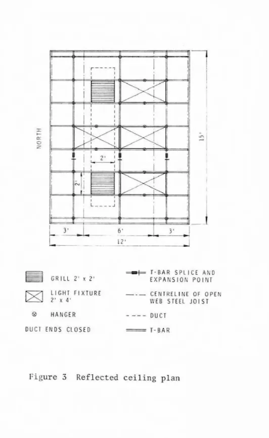
Details of t h e t e s t specimen are shown in Figures 2 and 3; the item numbers below correspond to t h e p a r t numbers in Figure 2.
(4.83 m), w i t h an e f f e c t i v e span o f 15 f t G i n . (4.72 m ) , moment o f
i n e r t i a 3 8 . 3 8 in.4 (15.97 x ~ L I ~ r n r n ~ ] fabricated of CSA 640 20-44W steel. 2. S t e e l r o o f deck unit, fluted 8 in. (205 mm) O . C . 0 0 . 0 3 0 in. (U.76 mmj
wiped zinc-coated s t e e l , 14 i n . (38 mm) deep by 311 i n . (762 ~ n m ) wide.
Deck units a t t a c h e d t o t h e j o i s t s w i t h $-in. 133 mm) arc s p o t w e l d s
(puddle w e l d s ) t h r o u g h welding washers 16 in. (406 m j O.C. Interlocking flanges of a d j a c c n t units were crimped t o g e t h e r on 24-in. (610 m ) centres.
5. Concrete t o p p i n g , I i n . (25.4 mm) deep over t o p of steel deck. Density 1 4 9 l b / f t 3 (2388 kg/m3], 3,300 p s i ( 2 2 . 8 MPa] average compressive
s t r e n g t h , placed a t 3 in. slump.
4 . Vapour b a r r i e r .
5 . Mineral board i n s u l a t i o n , 15 i n . (38 mm) i n two 3 / 4 - i n . (19 m) layers, t o t a l thermal resistance 4.4 f t 2 bb " F / B ~ U (0.77 m2 K / W )
.
6 . Roof c o v e r i n g , 3 - p l y f e l t membrane w i t h a s p h a l t interlayers.7 . S t e e l duct, e n d s c l o s e d , manufactured from 0 . 0 2 4 - i n . ( 0 . 6 mm) g a l -
v a n i z ~ d s t e e l 1 2 in. (305 mm) by 24 in. (610 mm) cross-section, by 1 2 ft
( 3 . 6 6 m) l o n g , provided with t w o h e a d e r s 18 i n . 2 (456 rnrn2).
8. D i f f u s e r grille, 24
in.2
(610 m m 2 ) , lay-in type (compatible w i t h sus- pension system) c o n s t i t u t i n g an opening a r e a o f 6 4 0 in.2 / I 0 0ft2
(4.44%]of
ceiling arca.9 . Recessed-type l i g h t i n g f i x t u r e , nominally 2 f t (610 rnm) by 4 ft
( 1 . 2 2 m), manufactured from 0,024-in. (0.6 mm] steel, compIete w i t h b a l -
l a s t and lamp8iolders. F o u r f i x t u r e s were used constituting an area of 1 8
pcr cent of t h e ceiling a r e a .
1 0 . Main t e e x , manufactured from 0 . 0 2 0 - i n . ( 0 . 5 mm) wiped zinc-coated stecl, 12 ft 1 2 - 6 6 m) l o n g , 1% in. (38 mm] deep with a I - i n . (25 mm) f l a n g e capped w i t l a a white p r e - p a i n t e d steel 0.OIO in. ( 0 . 2 5 mm) thick. Each length of member i n c o r p o r a t e s one expansion point.
11. Cross t e e * , same s e c t i o n as main t e e , equippcd with interlocking ends, supplied i n 4 ft ( 1 . 2 2 m) and 2 ft (610 mm) lengths.
1 2 . Mineral f i b r e b o a r d a c o u s t i c a l c e i l i n g panel*, n o m i n a l l y 24 in. (610 mm) by 4 8 i n . 11220 rn) by 5/8 in. (16 mm) thick.
13. P e r i m e t e r moulding angles (not shown) , 1 2 - f t ( 3 . 6 6 rn] long 3 / 4 - i n .
(19 mrn) by 3 / 4 - i n . (I!, mm) angle s e c t i o n manufactured from 0 . 0 2 1 - i n .
(0.5 mm) wiped zinc-coated s t e e l .
" L i s t e d and labelled by Underwriters' L a b o r a t o r i e s of Canada; L i s t of
1 4 . Iinnger wire [not shown), 0.105-in. ( 2 . 7 mrn) galvanized s t c e l wire
spaced 24 i n . (610 mm) O.C. a l o n g main t e e s at t h e i n t e r s e c t i o n o f t h e crass-tees and a t centre a f cross-tees a d j a c e n t t o l i g h t i n g fixtures.
15. Ijald-down clips ( n o t s h o w t ~ ) , made from 0.015-in. ( 0 . 4 mm) s p r i n g
s t e c l , clampet3 o v e r b u l b o f t e e bars t o p r e v e n t tilcs from l i f t i n g .
16. Lighting f i x t u r e p r o t e c t i o n * * jnat shown), acoustical ceiling panel
placed on top o f lighting f i x t u r e leaving ends and sidcs open to p r o v i d e ventilation f o r t h e f i x t u r e .
17. Duct p r o t e c t i o n * " ( n n t shown), one acoustical c e i l i n g p a n c l c e n t r e d
over each o p e n i n g .
The assembly was designed to be simply s u p p o r t e d i n t h e r e f r a c t o r ) - c o n c r e t e frame o f t h e f l o o r f u r n a c e . Space w a s l e f t round t h e perimeter
t o a l l o w f o r thermal expansion; t h e c o n s t r u c t i o n i s t h c s e f o r e c l a s s i f i e d
as ' ' u ~ ~ r e s t r a i n e d ' b c c a r d i r r g t o the t e s t s t a n d a r d ULC-SlOl (33 [ASTPI E l 1 9
141
3
-
"Partial p r o t e ~ z i o n ~ ~ was designed f o r t h e lighting fixtures and d u c t w o r k t o reduce the c o s t of the f i r e resistive ceiling installation.
In addition, the service l i f e o f a recessed lighting fixtwrc increases considerably wllcn t h e f i x t u r e is well v e n t i l a t e d .
Construction and IVorkrnanshiu
A 1 1 structural c o n s t r u c t i o n was c a r r i e d out by members of the s t a f f
o f t h e Division o f B u i l d i n g Research. T h e r o o f i n g , ductrrork and ceiling installation were done by workmen in t h e employ o f local c o n t r a c t o r s .
The f o u r OWSJ were pIaced on b e a r i n g p l a t e s in the l o a d i n g frame and s t e e l deck was a r c spot welded t o t h e t o p c h o r d s o f t h e j o i s t s using % - i n .
(15 mm) welding washers 16 in. (406 mm) O.C. Interlocking fIanges of ad- jacent units were crimped t o g e t h e r on 2 4 - i n . (610 mm) centres. A wooden form was constructed round the perimeter of t h e roof deck t o p r o v i d e t h e d e s i r e d 1 - i n . ( 2 5 mm) concrete cover. One c u b i c yard (0.765 m3) of r e a d y - mix concrete from a local source was dcsigned t o y i e l d a m i r ~ i m u m compres-
sive strength o f 3000 p s i ( 2 0 . 7 MPa); t h e mix comprised t h e following:
p o r t l a n d cement p i t sand g r a v e l a g g r e g a t e ~ s a t e r 420 # 1191 kg) 1400 # (636 kg) 1780 # (809 kg) 265 t! I120 kg)
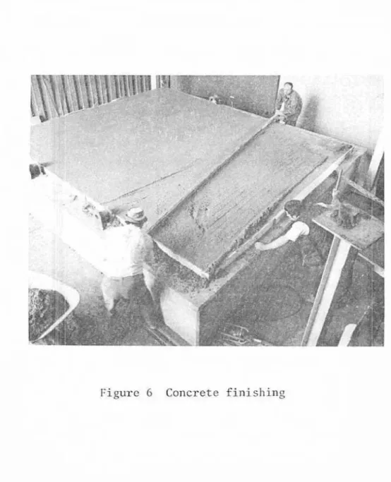
F i g u r e s 4 to 6 are photographs o f t h e sample during the construction process. Slump of t h e concrete a t time o f placement a v e r a g e d 3 i n . (76 mm).
**
T h i s t y p e o f protection is known as "partial protection" ( 2 ) and i sTWQ cylinders of c o n c r e t e were t a k e n f o r compressive t e s t s .
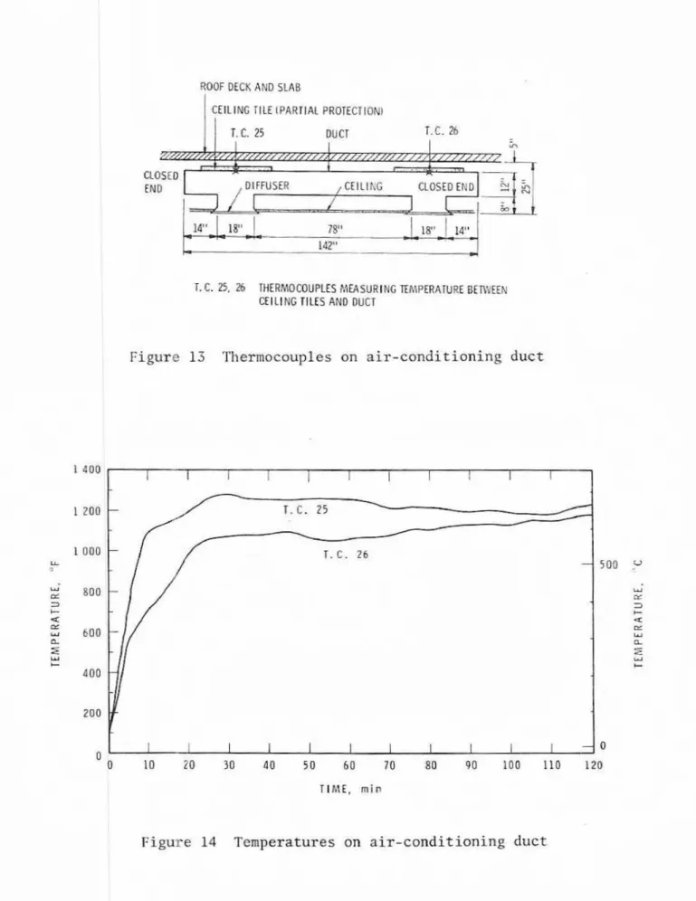
The d u c t w o r k , ceiling and lighting f i x t u r e s w e r e i n s t a l l e d and located a s shown i n Figure 3 . Both t h e t o p s of t h e headers t o the d u c t
and t h e t o p s of t h e lighting fixtures were p r o t e c t e d by l a y i n g on a
f u l l - s i z e cciEing panel to p r e v e n t radiative heat transfer. Workmanship
on a l l parrs a£ t h e specimen was j u d g e d t o he good.
F I R E TEST
The specimen \<as s u b j e c t e d t o f i r e t e s t i n accordance w i t h t h e
provisions of ULC 5101-1975 (31 (ASThI E 1 1 9 - 7 3 ( 4 3 ) . Avcrage moisture con- t e n t of the concrete t o p p i n g w a s 2 p e r cent by weight at the time of the
test.
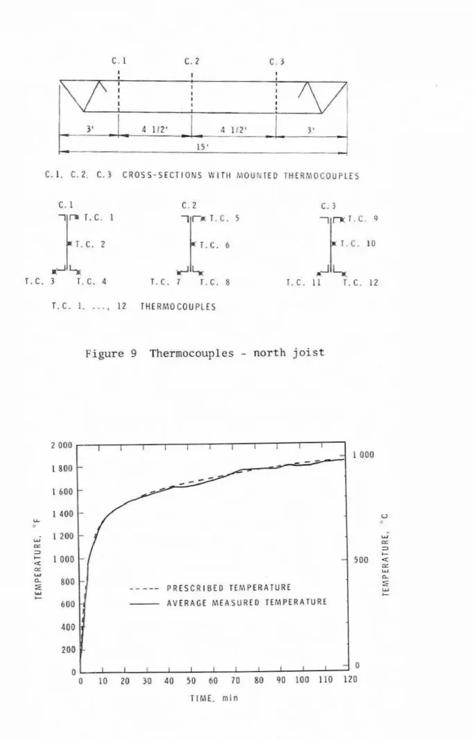
Gas flow i n t o t h e furnace was controlfed automatically so a s to f o l - low c l o s e l y the temperature-time c u r v e p r e s c r i b e d hy t h e s t a n d a r d . Fur-
nace temperature was measured by n i n e s p n ~ e t r i c a l l y distributed thcrmo-
couplcs enclosed i n 13/16-in. (20.6 mm) Q.D. inconel t u b e s h a v i n g a w a l l t h i c k n e s s o f 0 . 0 3 5 i n . (0.89 mm) and equipped w i t h a carbon s t e e l cap a t t h e t o p . The h o t j u n c t i o n of t h e thermocouplcs was p l a c e d I 2 i n . (305 mm)
from t h e exposed f a c e of t h e specimen. Both individual telnpesatures at
t h e n i n e p o i n t s and t h e average were recordcd d u r i n g t h e test.
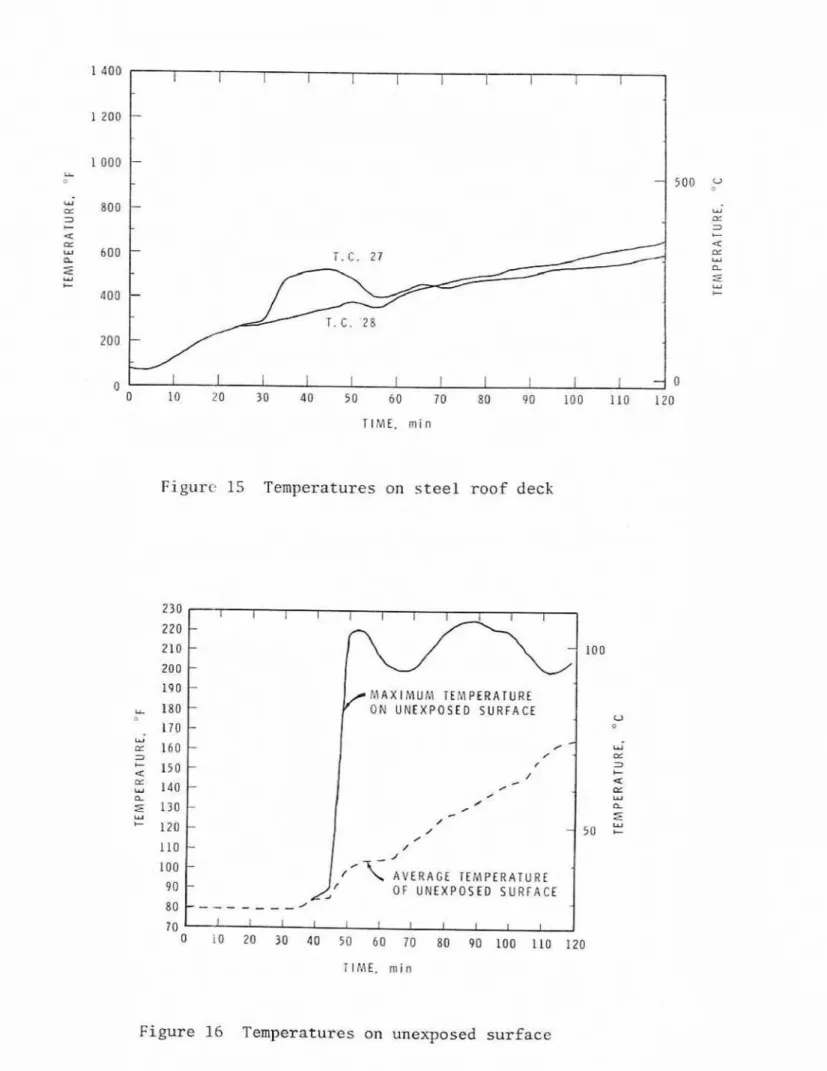
Temperature on the unexposed s u r f a c e was rneasurcd by n i n e themo- c o u p l e s ; f i v e were located at t h e c e n t r e and q u a r t e r p o i n t s of thc assem- b l y ; f o u r o t h c r s were l o c a t e d adjacent t o p a r t i a l l y protected f i x t u r e s . A l l unexposed s u r f a c e thermocouples wcre covered with standard asbestos pads 6 i n . (152 mm] s q u a r e and 0 . 4 in. (10 mm) t h i c k .
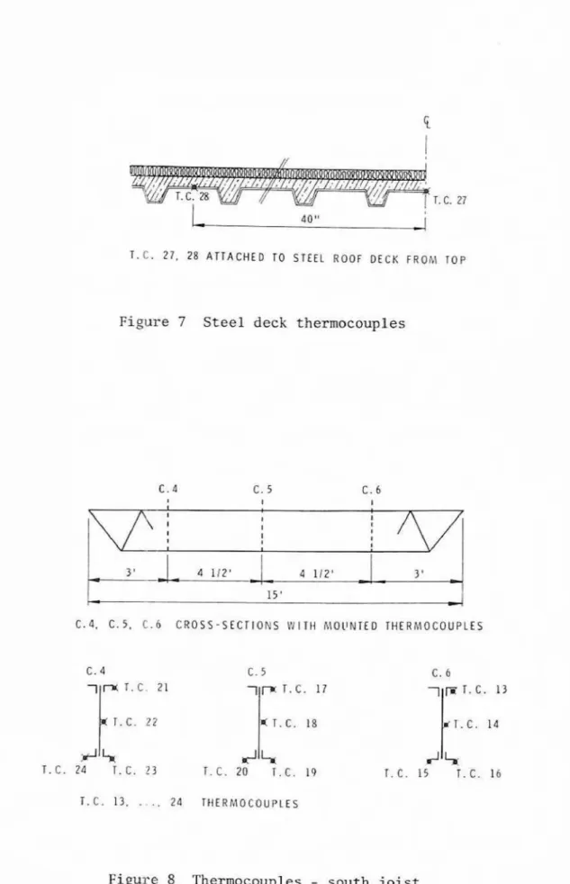
S t e c l deck temperatures were measurcd a t t h e c e n t r c of t h e assembly and at a p o i n t 40 in. (1016 mm) a l o n g t h c centreline o f the assembly, as
shown in Figure 7.
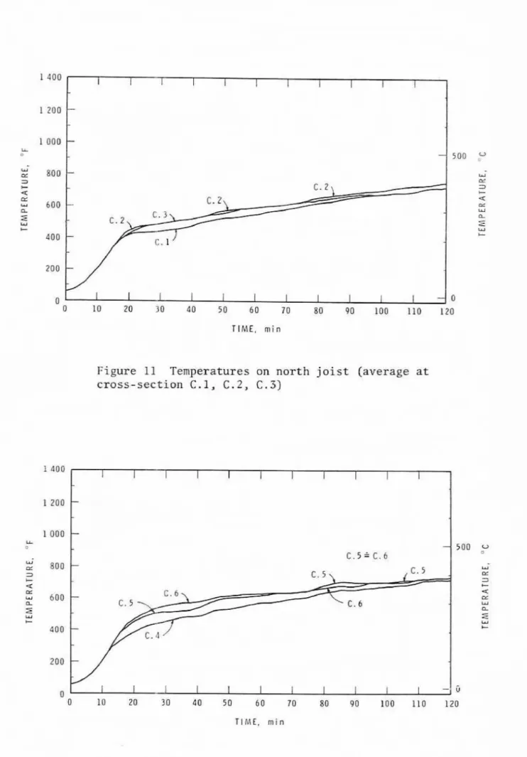
Joist temperatures were measured at 24 p o i n t s a t t h e c e n t r c and
q u a r t e r s p a n s , Location o f t h e thermocouplcs on t h e cross-section is shown i n Figures 8 and 9 .
D u r i n g t h e t e s t a l i v e l o a d of 50 l b / f t 2 (2394 bJ/rn2) was a p p l i e d t o t h e r o o f assembly. To e t h e r w i t h t h e estimated dead load (self-weight)
5
o f 2 2 1 b / f t 2 ( 1 0 7 kg/m ) t h e a p p l i e d l o a d w a s c a l c u l a t e d to s t r e s s the s t e e l joists and deck to t h e maximum allowable by CSA S16-1969 (5). 'l'he
l i v e l o a d d e f l e c t i o n o f t h e assembly was 0 . 3 1 2 i n . ( 7 . 9 mm] measured a t
t h e c e n t r e of each j o i s t b y an electrical d e v i c e . At t h e start o f t h e
t e s t t h e deflection w a s zeroed so t h a t deflections due t o t h e e f f e c t s o f
E i r e on t h e assembly were recorded d u r i n g t h e f i r e t e s t .
Several thermocouples were distributed t h r o u g h o u t t h e plenum space to measure temperatures o f t h c unexposed ceiling f a c e , a i r , and ductwork.
OBSERVATIONS
Significant o b s c s v a t i o n s wcrc recorded d u r i n g t h e f i r e t e s t . A t 3 min t h e ceiling panel s u r f a c e had d a r k c n c d and t h e e x p a n s i o n points on t h e main runners had operated. It was n o t e d that t h e f l a n g e at onc of d h e s e p o i n t s had buckled upward i n s t e a d o f downward a s t h e d e s i g n i n t e n d s .
A t about Ifl min t h e cei 1 i n g panels had l i g h t c n e d again and t h c s u s p e n s i o n system was d e f l e c t i n g s l i g h t l y dormward. T h i s gradual deflection con-
t i n u e d u n t i l the t e s t was t e r m i n a t e d . No p a n e l s dropped from t h e ceiling during t h e f i r e t e s t .
No changes were o b s e r v e d on the unexposed s u r f a c e , e x c e p t t h a t small
q u a n t i t i e s of smoke were generated d u r i n g t h e e a r l y m i n u t e s . ? ' h i s was produced by t h e lighting fixture ballasts and t h e combustible c o n t e n t of
t h e m i n e r a l f i b r e c e i l i n g p a n e l s .
RESULTS
Because roof assemblies i n Canadian b u i l d i n g s r e q u i r e a maximum f i r e
r e s i s t a n c e r a t i n g o f 2 h , t h e f i r e t e s t i m s terminated a t 2 h 5 min. A t
t h i s time no f a i l u r e p o i n t , a s j ~ r c s c r i b e d i n t h e t e s t s t a n d a r d , had been rcachcd. Accordingly, t h e f i r e resistance classification of t h e assembly i s 2 h .
Information r e l a t i n g t o t e m p e r a t u r e s developed i n t h e f u r n a c e and in t h e tcst assembly is Tllustrated in Figures 10 to 16; t h e y a r e labelIed s o a s to be self-explanatory.
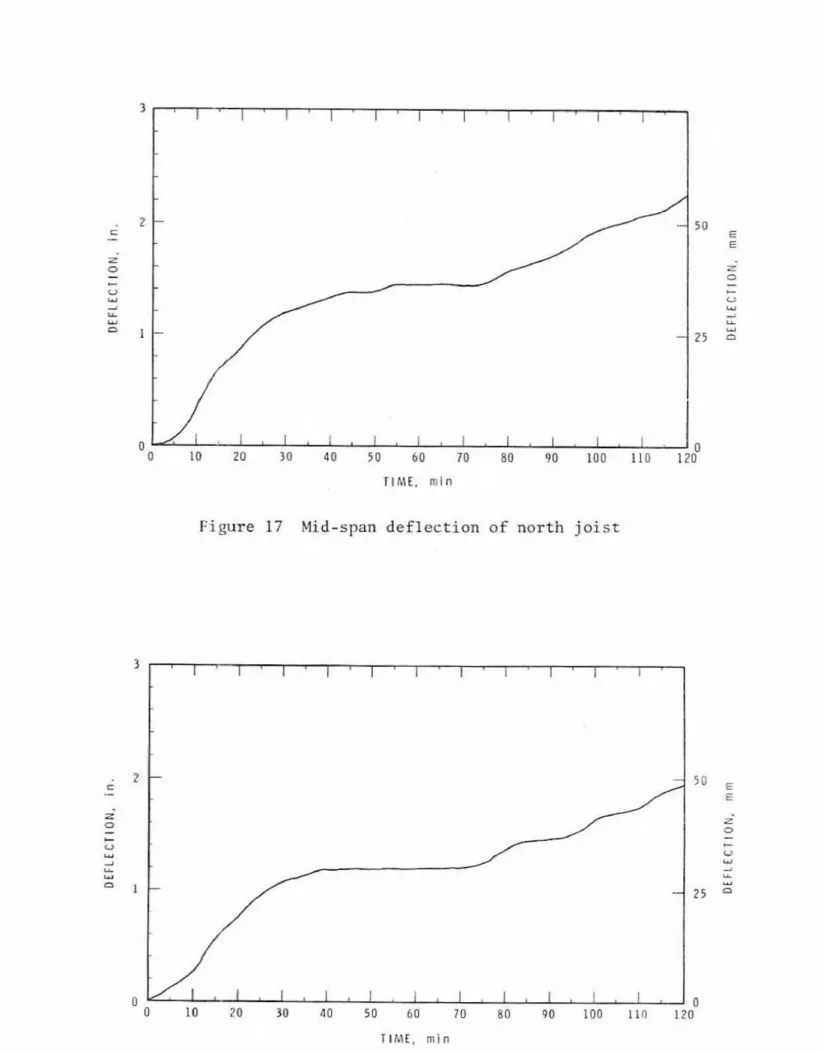
U c f l c c t i o n s measured over each j o i s t a t t h e c e n t r e l i n e o f t h e a s s e m b l y are shown i n Figures 17 and 1 8 .
P r o v i s i o n af t h e 1 - i n . concrete cover [heat sink) changed t h e fire
e n d u r a n c e time of t h e assembIy from b a r e l y 1 h t o o v e r 2 h , as had been
a n t i c i p a t e d i n t h e dcsign. 'Ibis test demonstrated once a g a i n ( 6 ) how e f -
f e c t i v e a h e a t c a p a c i t y remote from t h e fire-exposed surface can be i n p r o l o n g i n g t h e f i r e r e s i s t a n c e o f a c o n s t r u c t i o n assembly. From t h e tem- peeraturc c h a r t s it may be seen t h a t " p a r t i a l p r o t e c t ion" (2) was q u i t e e f f e c t i v e i n minimizing heat transmission t h r o u g h ductirtork and lighting
fixtures. It i s recommended that t h i s econamical p r o t e c t i o n be used i n p l a c e of l i g h t i n : f i x t u r e protection boxes and E i r e s t o p f l a p s ( c e i l i n g dampers).
CONCLUSIONS
I . 'The f i r e resistance classifica~ion o f t h e r o o f ceiling assembly t c s t e d is 2 h according t o t h e c r i t e r i a f o r acceptance o f ULC S l 0 1 - 1 9 7 5
(ASTM E119-7.3).
2 . A 1 - i n . concl-ete t a p p i n g on s t e e l roof d e c k r e s u l t s i n mudl improved
f i r e e n d u r a n r c and s t r u c t u r a l q u a l i t y , as compared t o r o o f - d e c k w i t h - out c o n c r e t e t o p p i n g .
3 . " P a r t i a l p r o t e c t i o n " ( c h a t i s , p l a c i n g a c e i l i n g p a n e l on t o p o f a l i g h t i n g fixture) i s satisfactory f o r this t y p e of asscmbly and o f f e r s c o n s t r t ~ c t i o n economy.
1. Protection o f cci l i n g opcnirlgs f u r a i r 1a;lnclling 1,- "j1;11-t i31 11sotcc-
t i o n " ( p l a c i n g 3 ceiling p a n e l an t o p o f tllc d u c t o v c r t l ~ c hcador] proved to be s a t i s f a c t o r y . T h i s installation is a substitute for the r a t h e r c o s t l y f i r e - s t o p f l a p o r c e i l i n g damper normally used.
T h i s p r o j e c t \<as p a r t o f a cooperation agreement between t h e N a t i o n a l Research C o u i r c i l o f Canada and t h e Canadian S t e e l I n d u s t s i c s
C o n s t r u c t i o n C o u n c i l known as t h e S t e e l I n d u s t r i e s F e l l o w s h i p Program. 'I'his r e c o r d o f t h c p r o j e c t is p u b l i s h e d w i t h t h e approval of t h c l l i r e c t e r
o f t h e Division o f h i f d i n g Research and t h e Chairman o f t h e Canadian
S t e e l I n d u s t r i e s C o n s t r u c t i o n Council.
REFERENCES
1. S t a n z a k , Il'.lV, a n d L. Konicek, Effect of T h e r m a l Insubation and
Heat S i n k on t h e Structural F i r e Endurance o f S t e c l Roof Assemblies.
Canadian Journal o f C i v i l E n g i n e e r i n g , Vol. 6 , No. 1, March 1979, I'
-
5 2 - 3 5 .2 . S t a n z a k , lf.l\r., O p e n i n g s i n Fire P r o t c c t i v c Ceilings: Lxpcrirncntal i n v e s t i g a t i o n s nn Stecl-Supported Construction. Division of Building 17cscarch, Nat i o n 2 1 licscarch C o u n c i l o f Canada, Bui l d i n g Research N o t e
No.
5 . ULL-S101-1975, S t a n d a r d Metl~ods o f Fire Endurance T e s t s o f B u i l d i n g C o n s t r u c t i o n a n d Materials. Underwritersf Laboratories a f C a n a d a ,
Scarborough, 1 9 7 5 .
4. AS'TF.1-EI19-73, S t a n d a r d Methods of Firc T e s t s of Building Construction
and M a t e r i a l s . American S o c i e t y f o r T e s t i n g and Y a t e r i a l s , P h i l a d e l p h i a , U . S . A . , 1973.
5 . CSA 516-1969, S t e e l S t r u c t u r e s f o r B u i l d i n g s . Canadian S t a n d a r d s Association, Kcxdale, 1965.
6 . S t a n z a k , I9.W. and 'S.Z. Marmathy, E f f e c t of Deck on Failure Temperature o f S t e e l Beams. F i r e Technology, \'ol. 4, X o . 4 , 1968, p . 2 6 5 - 2 7 0 .
Figure 1 Dependence o f f i r e resistance on thickness of concrete topping
4 10
G R I L L 2 ' r 2 ' ==@=== T - B A R S P L I C E A N D E X P A N S I O N P O I N 1
[XI
k!:Hl, F I X T U R F C E N T H f l l N E O F O P E N i8JEB STEEL J O I S T 8 H A N G E R - --- D U C T DUCT E N D S C L O S E D I - B A RT . C . 2 7 , 2 8 A T T A C H E D T O S T E E L R O O F D E C K FRQhl T O P
F i g u r e 7 S t e e l deck thermocouples
C . 4 . C . 5. C . 6 C R O S S - S E C T I O N S \ V I T H h l O l l N T f D T H F R M O C O U P L E S
Figure 8 Thermocouples - south j o i s t
C . 4 C. 5 C . 6 1 T Y T . C 21
I
T . C . 2 2 7wT.C. 17 7 p T . C . 13 *l T . C . 1 8I.
T. C. 144 %
I.C. 24 T. C. 2 3 T - C. 20dh
T . C . 1 9 T. C 15d 4
T . C . 16I
y
I I 4 1 t 2 ' 4 112" 3 ' 1 5 '+
C. 1 , 13.2. C. 3 C R O S S - S E C T I O N S W l T H M O U W T E D T H E R A I O C O U P L E S T . C . 1 . . . . " 1 2 T H E R M O C O U P L E S C. 1 C. 2 E. 3 1 P T . C . 1 1 n T . C . 9Figure 9 The~mocouples - north j o i s t T . C . 6
*"L*
--- P R E S C R I B E D T E M P E R A T U R E A V F R A G E M E A S U R E D TEMPERATURE*
T . C . 1 0 T I K I E , m i n T - C . 3 T. C . 4 T . C . 7 1 . C . 8 T . C . 11J&
T . C . 12TlhlE, rnin
Figure 11 Temperatures on n o r t h j o i s t [average at cross-section C . l , C.2, C.3)
0 i,
0 10 20 30 40 5 0 b 0 70 80 90 100 110 120
T I M E , m i n
Figure 12 Temperatu~es on south j o i s t (average at cross-section C . 4 , C . 5 , C - 6 )
ROOF DECK AND SLAB
I
I
F I L I N G TILE IPARTIAL PROTtCTlONlDUCT S . C . 2h
T. C. 25. 26 THERMOCOUPLES MEASURl NG KR1PERAWRE BEIISEEN
CEILING TILES AND DUCT
F i g u r e 13 Thermocouples on air-conditioning d u c t
TIME, m i n
TIME. m i n
Figurc 15 Temperatures on steel r o o f deck
Figure 16 Temperatures on u n e q o s e d surface
230 ..
,
220 210 I 1 I - - 100 20 0 190 MRXFMUM T E M P E R A T U R E 180 1 7 0 W 1 6 0 1 O N U N E X P O S E D S U R F A C E $ 150 140 e s 1 3 0 Y + 120 110-
/ - - --
100 90 80 70 I U 0 N - - A OF U N E X P O S E D S U R F A C E- - - -
- - - - C 1 1 1. I 1 1 I I I I I 0 10 20 30 40 50 60 7 0 80 90 100 110 120 TIME. m i n ,' r / / - / / fl-
1 / 0 - / E =I C u c W t~ z 4 50 cTIME, m i n
Figure 17 Mid-span deflection o f n o r t h j o i s t
3
2
TlhlE, m i n
F i g u r e 18 Mid-span deflection of south joist
/ m l ' ~ ' ~ T ~ l 1 /. 1 ~' ~ , ~ q ~ - - - 50 E E - Z D - - ' l q " l ' l ' l n l n l -C 0 Ly