HAL Id: hal-02915246
https://hal.archives-ouvertes.fr/hal-02915246
Submitted on 13 Aug 2020
HAL is a multi-disciplinary open access
archive for the deposit and dissemination of
sci-entific research documents, whether they are
pub-lished or not. The documents may come from
L’archive ouverte pluridisciplinaire HAL, est
destinée au dépôt et à la diffusion de documents
scientifiques de niveau recherche, publiés ou non,
émanant des établissements d’enseignement et de
Experimental study of single and two-phase adiabatic
flow distribution in compact heat exchangers
Frédéric Poggi, Hélène Macchi-Tejeda, Alain Maréchal, Denis Leducq, André
Bontemps
To cite this version:
Frédéric Poggi, Hélène Macchi-Tejeda, Alain Maréchal, Denis Leducq, André Bontemps. Experimental
study of single and two-phase adiabatic flow distribution in compact heat exchangers. 18e Congrès
Français de Mécanique, 2007, Grenoble, France. �hal-02915246�
Experimental study of single and two-phase adiabatic flow distribution in compact heat exchangers.
Frederic
Poggi (a), H
el
en
eMa
cch
i-T
ej
eda (a), Alain Marechal
(b), Denis Leducq(a),
And1·eBontemps
(b,c)(a) Cemagref, GPAN, Pare de Tourvoie, BP 44, Antony, 92 163, France
(b) CEA - GREThE, 17 avenue des martyrs, Grenoble, 38 054, France
(c) Universile Joseph Fourier, LEG!, 1021, rue de la piscine, Saint Martin d'heres, 38 042, France
Corresponding author: frederic.poggi@cemagref..fr. Tel: + 33 1 40 96 61 21 Abstract:
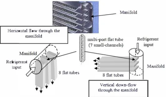
Small-channel heal exchangers are widely used for car air-conditioning. However information about theh" behaviour remains scarce. An experime111al device was built to characterize the distribu1ion o.f single and two-phase adiabatic flows in a small channel heal exchanger, and to measure ils singular and regular pressure losses. A transparent polycarbonate test section comprised a 16 mm dia1neter header connected to 8flat tubes with 7 small channels (D11 = 0.889 mm). Both were studied with horizontal flow
and vertical down-flow through the manifold. The mass flux range was between I 5 and 650 kgl(m2.s) in the manifold and between 100 and 3 000 kgl(m2.�) in the small channels. The range of vapour quality values at the test section inlet was b.etween 0.1and0.9. The two-phase refrigerant was condensed at the outlet of each flat tube in order to measure each flow rate separately.
Resume:
Les echangeurs de chaleur compacts a mini-canaux sont largement repandus dans la climatisalion automobile. Cependant /es informations sur leur comportement demeurent rares. Un dispositif experimental est realise pour caracteriser la dislribution des ecoulements adiabatiques mono- et diphasiques dans un echangeur compact a mini-canaux. Les pertes de pression singulieres et regulieres sonl mesurees. Une section d'essai en polycarbonate transparente comportant un distributeur de 16 millimetres de diametre relie a 8 barrettes de 7 mini-canaux (D1, = 0.889 mm) est realisee. Deux
configurations sont etudiees : ecou/ements horizontal et vertical descendant dans le distributeur. La gamme de densite de flux massique varie de 15 a 650 kgl(m2.s) dans le distributeur et de 100 a 3 000 kgl(m2.s) dans Jes mini-canaux. Les valeurs de titre en vapeur en entree de section d'essai sont comprises entre 0,1 et 0,9. le refrigerant diphasique est condense en sortie de chaque barrette a.fin de mesurer chaque debit separement.
Key-wor
ds
:Distribution ; compact beat exchanger ; small channel ; pressure drop
1
IntroductionThe study described in this paper answers a triple objective:
- Environmental objective: reduction of the refrigerant charge of refrigerating systems
thanks to the implementation of small-channel heat exchangers (protocols of Montreal [1987]
and Kyoto [I 997]),
- Industrial ob
j
ective
:
the studied exchanger is similar to automobile air-conditioners or
1 �,. C 011gi·es Frnm;nis de Mecanique Gre11ob/e, 21-31 aOlif 2007
- Scientific objective: to folftl the lack of data and models concerning distribution and singular pressure drops on millimen·e scale n1bes.
Thus, this work experimentally snidies a p011ion of small-channel beat exchanger with li
q
uid single-phase flow and two-phase flow. The selected geometry is that of the automobile's
equ
i
p
m
e
n
ts
(FI
G
.
1).
Amanifold distributes the refrigerant in the small channels of
8successive
extmded flat tubes in two positions (holizontal flow and vertical down-flow in the manifold). This geometry can be industrially manufacmred by fining together the flat tube inlets inside themanifold
bya protrns
i
on
.
The tube protrnsion depth
i
nt
o the manifold will also affect the
dis
tr
ibu
ti
on. Webb and al. (2004) and Hrnjak (2004) provided recent reviews on this subject.
In this paper, we smdied the refii.gerant distribution; regular and singular pressure drops in the small-channels and along the distributor were also studied by Poggi and al.(2007),
but are not presented in this paper.Horizontal flow through the manifold
Refrigerant input
8 flat tubes
Manifold
multi-port flat tube (7 small-cham1els)
Refrigerant
8 flat tubes
Vertical dov.·n-flow through the manifold
Manifold
FIG. 1 -Distributor for small-channel heat exchangers used in industrial applications.
2 Experimental device 2.1 General desniptioo
The
FIG.2 describes the exp
e
rimental device. It consists of 4 main loops
:
- The evaporation loop: providing vapour quality at the inlet of the test section,
- The test loop: including the test section,
- The condensatio
n
loop
:
providing heat balance at the outlet of the test section,
- The subcooling loop: to avoid pump's cavi
t
a
ti
ons in
t
he test loop.
A
Wafer-Mag Brooks electromagnetic and a Danfoss Mag 1100 flowmeters were
respectively used to measure the mass flow rate in evaporation(
t-.
+
/
-
0
.
020
%
of mass flow rate)and condensation
(!l+/-0.033% of mass flux) loops.
Thevapour quality was set at the in
l
et of
the test section thanks to the evaporation loop.
Iut
he test loop, all tubes were well insulated in
order to consider the flow as adiabatic. A special attention was given in a device design and manufacniring in order to minimize instabilities in the whole loop, especially for the two-phaseflow.
Test
loop
Evaporation
loop
Subcooling:
�
--
oop
Flov.mere:r (Evaporation loop) 2 Pump (Test loop)
3 Bypass Valve
4 Control Valve
S Flov.weter (Test loop) 6 8 flowmeters (Test loop)
7 Flov.mete:r (Condensation loop)
8 8 Flowmeters (Condensation loop)
9 Control Valve (Condensaion loop)
T Temperature sensor
P Pressme sensor
M Differential pressw·e sensor
FIG.
2
-The expe1imental device.
2.2 Test section
The t
es
t section was built in polished polycarbonate in order to visualise the flows inthe
manifold and in the small ch
annels.
Them
anifold
diameter is 16 mm with a 90 mmlength;
8m
ulti-po
r
t flat tubes are inserted inside
the manifold. Each fiat tube cont
ains 7 r
ectangular small channels (Dh =O.S89
nun)
(FIG.1,
3). The r
efrigeran
tHFE-7
1
00 was used
inor
d
er to cany ou
t experiments dose to atmospheric pressureand
ambient temperature.Manifold ... Ho1izontHJ flow • th
ro
ugh the manifold -Refirigenmtl;;'
�
..�
mm=rn
�
input 8parall
el flHt tubes"'-.
"' · ' " · " · tubesl J I I
RefrigerHnt outlet to condensers aod flowmetersFIG. 3 -
Representation and photographs of the
t
es
t
se
ctio
n.
The instrnme
n
ta
ti
on allows
themeas
ur
em
en
t
of
th
e flow rate and the vapom quality at
theoutlet of each multi-p011 flat tube
.
The distribution of the flow ra
t
e
i
n
t
he manifold can be
d
e
t
ermined as a fhnc
t
i
on of
theinlet vapour quality
andtotal tlow rate
.
ADanfoss
M
ass 2
1
00
mass flowmeter
(
/!!.
+
/
. 0.033%) was
installed at the inletof the test section. The temperature was
measured
witha p
l
at
inumresistance
sensor
(
il
+/
-
0.3%) and the pressure was
measured with anabsolute pressure sensor Rose
m
ount0
/
2
bars(
A
+/
-
0.2%).
At the outlet of the test section,8
1 �,. C 011gi·es Frnm;nis de Mecanique Gre11ob/e, 21-31 aOlif 2007 and outlet temperatures of condensers were measured with
16 platinum resistance sensors
(1'!+/-0.3%), bo
th on the refrigerant side and on the water side. Two sets of 8 mass flowmeters Micromotion type F (11+/-
0.3%) were used to measure respectively the flow rates in the fla
t tubes and on the water side. A heat balance was pe1fonned on the water circuit to determine the vapour quality at the outlet of each flat tube. The instmmentation of the test section was transfened to a high speed data logger "N ational instmments NI SVXI
-1000
"
connected to a computer.3 Results and disrnssion
3.1 Single phase flow distribution
The range of mass flux was
15
to650
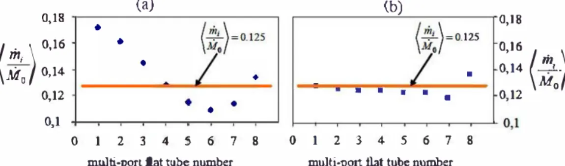
kg/(m2.s) at the inlet of the test section. The dimensionless flow rate in each flat rube \flow rate per flat tube/total flow rate at the inlet of the test section) is presented in the Figure 4. In vertical down-flow through the manifold, the dimensionless representation shows a rather homogeneous distribution whatever the inlet flow rate, the mean dimensionless flow rate being0.125 (± 0
.
03
)
in each multi-port tube. In horizontal flow through the manifold (a), the distribution is less homogeneous, with over providing of the3
first flat rubes. This could be explained by the gravity.0,18
(
m;l
0,16M
0,14 0 0,12 0,1 • • \a) (b)(
tt;)
=
0.
1
25
(�)
=
0
.125 :::: ( )
• 0/
•/
• 0,14";;0
I • • • • 0 12 • • • . ' 0 1 2 3 4 5 6 7 8 0 1 2 3 4 5 6 7 8multi-port flat tube number multi-port flat tube number
FIG. 4 -Repartition of the mass flow rates at the outlet of the multi-poll flat tubes.
(a) Horizontal flow through the manifold,
(b)
Vertical down-flow through the manifold.This quite good distribution in both distributor positions is in good agreement with the rule given by Peny & Green
(1997
).
These authors indicated that a homogeneous distribution is obtained with a ratio of10
between the pressure drop in the manifold and that in the small channels (for vertical down-flow. the maximal pressure drop in the manifold was to300
Pa and17
000 Pa in the small channels; for horizontal flow, the maximal pressure drop in the manifold was to340
Pa and20 000
Pa in small-channels). Nevertheless, the "accumulative pressure" forces the refrigerant towards the last multi-port flat tubes.3.2 Two-phase flow distribution
The flow rate distribution in the small channels was measured for different vapour qualities at the test section inlet. The mass flux was in the range of
35
to1 20
kg/(ni2.s) and the flow inside the manifold was recorded for each flow rate and vapour quality.3 . 2.1.
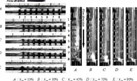
Visualisation of the flow patternsFIG.
5
shows the flow pattern in the manifold for a55
kglh mass flow rate. Ill the case of horizontal flow, at low vapour qualities \x �0. 15),
an intermittent flow was observed \slug flow+ stratified flow), with the whole manifold flooded. For medium vapour qualities
(0. 15
< x <0.60),
a wavy flow was obse1ved, as already seen by Watanabe and al.(1995).
Forx >
0
.
60,
tlle flow was semi-annular with stratification and droplet wrenching at the impact with the first flattube. For tbe higber vapour quality
(x
=0.85), an
annular flow was obse1ved before tbe impactof tbe fluid witb the first fl.at tube; tben the droplet wrenching led to fog formation. In tbe case
of ve11ical down-flow, for all vapour qualities, we obse1ved an annular flow with liquid
accumulation at bottom. All the bigber then the inlet vapour qu ality was low. On the contra1y,
tbe thickness of tbe annular liquid fihn decreased as tbe q
u
ality increase. Ftllthennore thegravity effect amplified botb tbe thinning of the liquid film in annular down-flow before the
impact of tbe fluid on tbe first flat tube and tbe l iquid accumulation in tbe rear of the manifold.
Droplet wrenching was also observed wben the fluid impacted tbe first flat tube; wben the
vapour quality increased, tbe droplet wrencbing led to fog formation.
Flow dirllCtiM --�
&
.e
iiliblj1�
'
!!!il
r
�
A - ·�--· -:!:! 0 � B � 1
�
2[
3I
4 5 6 c D 7 g E A B c D E A :X;n=15% B :xin=30% C:X;,,=45% D:X;11=75% E:X;11=90%FIG. 5 -Photogrnph of the flow patterns in the manifold for a 55 kg/b mass flow rate and
various inlet vapour qualities for both positions (a) horizontal flow (b) vertical down-flow through the manifold.
3.2.2. Influence of the inlet vapour quality on tbe distribution
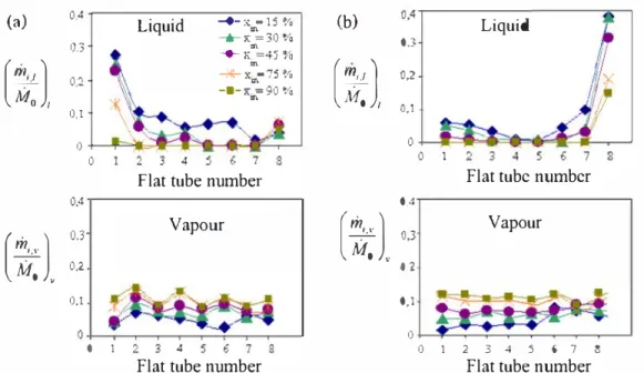
FIG. 6 shows tbe liquid and vapour dimensionless mass flow rates in tbe
8
multi-port flat tubes for both hmizontal flow and vertical down-flow througb the manifold in adiabatic condition for a55
kg/h mass flow rate. In the case of borizontal flow, the liquid dimensionless mass flow rate bad a quite high value for the first channel because of gravity. Then, tbe liquid dimensionless mass flow rate grndually decreased as tbe cbannel number increased, excepted for the last flat tube. Indeed the "accumulative pressure" forces the liquid towards the last flat n1bes. The vapour dimensionless mass flow rate showed an opposite trend, especially for the low vapour qualities. Wben tbe inlet vapour quality increased, the liquid dimensionless mass flow rate decreased strongly in the first flat tube, but increased ligbtly in tbe last flat tube, so tbat the distribution tends to be more bomogeneous. In tbe ve11ical down-flow case, tbe liquid dimensionless mass flow rate also decreased as the cbannel number increased, fmther on the liquid dimensionless mass flow rate highly increased under the "accumulative pressure" forcing the liquid towards the last flat tube, effect amplified by the gravity. Tbe vapour dimensionless mass flow rate increased lightly as the channel nurriber increased, excepted the two last flat tubebecause of the liquid accumulation at tbe manifold bottom. Otberwise, for both manifold pos.itions, the va1iation of vapour disUibution was mucb less significant tban that oftbe liquid.
1 ff"'• Cong res Franr;ais de Meca11ique Grenoble, 27-31 aoiit 2007
(a)
0.4Liquid
-+-x. 111 -15 o/o(b)
0,4...,._K =30 % 0.3 0.3 U\ -.-;.:; =4� 'Yo
(�J,
m(
;;:
),
0,2 --'*"'" x ... -75 o/o 0,2 --9-K;,.=90 % 0,1 0,1Liquid
0 0 0 I 2 3 4 � 6 7 8 0 1 2 3 4 5 6 7 llFlat tube number
Flat tube number
0.4 0.4 0.3
Vapour
(�J.
0,3Vapour
(�J.
0.2 02 0,1�
0,1 0 0 0 I 2 3 4 5 6 7 8 0 I 2 3 4 5 6 7 8Flat tube number
Flat tube number
FIG.
6-
Dimensionless vapour quality for each flat tube for various inlet vapour qualities and
an inlet mass flow rate of
M
0 = 55kg/h for both positions (a) horizontal (b) vertical down-flow.
4
ConclusionsFlow distribution in small channels of compact heat exchanger has been experimentally
studied. In single-phase flows, the distribution did not depend on the inlet mass flow rate and it
was rather homogeneous in both configurations. However it was less homogeneous in the
horizontal flow than in the vertical one because of gravity.
Intwo-phase flows, for the
horizontal position, the flow patterns depended on the inlet vapour quality. On the contrary, in
the vertical position, the flow at the manifold inlet was always annular, whatever the inlet
vapour quality. As for the distribution, it was significantly affected by the manifold orientation
and the inlet vapour quality. When the inlet vapour quality increased, the phase distribution was
more homogeneous.
References