HAL Id: tel-01114217
https://hal.inria.fr/tel-01114217v2
Submitted on 10 Apr 2015
HAL is a multi-disciplinary open access
archive for the deposit and dissemination of sci-entific research documents, whether they are pub-lished or not. The documents may come from teaching and research institutions in France or abroad, or from public or private research centers.
L’archive ouverte pluridisciplinaire HAL, est destinée au dépôt et à la diffusion de documents scientifiques de niveau recherche, publiés ou non, émanant des établissements d’enseignement et de recherche français ou étrangers, des laboratoires publics ou privés.
verification and deployment of component-based
applications
Nuno Gaspar
To cite this version:
Nuno Gaspar. Mechanized support for the formal specification, verification and deployment of component-based applications. Other [cs.OH]. Université Nice Sophia Antipolis, 2014. English. �NNT : 2014NICE4127�. �tel-01114217v2�
UNIVERSITÉ DE NICE-SOPHIA ANTIPOLIS École Doctorale STIC
Sciences et Technologies de l’Information et de la Communication
THÈSE
pour l’obtention du titre de
Docteur en Sciences
Mention Informatiqueprésentée et soutenue par
Nuno Gaspar
Mechanized support for the formal
specification, verification and deployment
of component-based applications
Thèse dirigée par Eric Madelaine et co-encadrée par Ludovic Henrio
Soutenue le 16 Décembre 2014
Jury
Rapporteurs Frédéric Loulergue LIFO, Université d’Orléans
Alan Schmitt INRIA Bretagne Atlantique
Examinateurs Luis Barbosa Universidade do Minho
Yves Bertot INRIA Sophia Antipolis
Directeur de thèse Eric Madelaine INRIA Sophia Antipolis
iii
Résumé
Cette thèse appartient au domaine des méthodes formelles. Que ce soit par le biais d’approches automatiques ou interactives, l’objectif des méthodes formelles est d’accroître la confiance que l’on peut accorder aux propriétés d’un système. Dans cette thèse, nous concentrons leur application sur une méthodologie spécifique pour le développement de logiciels: l’ingénierie à base de composants.
Parmi tous les paradigmes de programmation, l’ingénierie à base de composants se présente comme une des approches les plus utilisées pour le développement de logiciels dans le monde réel. Elle met l’accent sur une séparation nette des préoc-cupations, ce qui le rend attrayant pour des buts industriels ou de recherche. En outre, elle permet des reconfigurations structurelles de l’architecture des appli-cations. L’avantage de la modification de l’architecture du logiciel vient de la nécessité de faire face à la multitude de situations qui peuvent survenir dans un système potentiellement massivement distribué et hétérogène. À cette fin, le Grid
Component Model (GCM) suit cette approche en fournissant tous les moyens pour
définir, composer, et dynamiquement reconfigurer les applications distribuées à base de composants.
Dans cette thèse, nous abordons la spécification formelle, la vérification et le déploiement d’applications GCM reconfigurables et distribués. Notre première contribution est un cas d’étude industriel sur la spécification comportementale et la vérification d’une application distribuée et reconfigurable: The HyperMan-ager. Cela favorise l’utilisation des méthodes formelles dans un contexte indus-triel, mais met également en évidence la nécessité d’approches alternatives et/ou
complémentaires afin de mieux répondre aux besoin de ces entreprises.
Notre deuxième contribution est une plate-forme, élaboré avec l’assistant de preuve Coq, pour le raisonnement sur les architectures logicielles: Mefresa. Cela comprend la mécanisation de la spécification du GCM, et les moyens pour raison-ner sur les architectures reconfigurables GCM. En outre, nous abordons les aspects comportementaux en formalisant une sémantique basée sur les traces d’exécution de systèmes de transitions synchronisés. Dans l’ensemble, elle fournit les premiers pas vers une plate-forme complète pour la spécification et la vérification des car-actéristiques structurelles et comportementales des applications GCM.
Enfin, notre troisième contribution est un nouveau langage de description d’architecture (ADL): Painless. En outre, nous discutons son intégration avec ProActive — un intergiciel Java pour la programmation concurrente et distribuée, et l’implantation de référence du GCM. Painless permet de spécifier des archi-tectures de GCM paramétrées, avec leurs reconfigurations structurelle, dans un langage déclaratif. La conformité avec la spécification de GCM est évaluée par le code fonctionnel certifié extrait de Mefresa. Ceci permet le déploiement et la reconfiguration sûre des applications du GCM.
Abstract
This thesis belongs to the domain of formal methods. Either by means of automatic or interactive approaches, the goal of formal methods is to increase the confidence one can place on a system’s properties. In this thesis, we focus on their application regarding a specific methodology for the development of software: component-based engineering.
Among all programming paradigms, component-based engineering stands as one of the most followed approaches for real world software development. Its emphasis on a clean separation of concerns makes it appealing for both industrial and research purposes. Further, it enables on-the-fly structural reconfigurations of the architecture of the application. The advantage of modifying the software architecture at runtime comes from the need to cope with the plethora of situations that may arise in a potentially massively distributed and heterogeneous system. To this end, the Grid Component Model (GCM) endorses this approach by providing all the means to define, compose and dynamically reconfigure component-based distributed applications.
In this thesis we address the formal specification, verification and deployment of distributed and reconfigurable GCM applications. Our first contribution is an industrial case study on the behavioural specification and verification of a recon-figurable distributed application: The HyperManager. This promotes the use of formal methods in an industrial context, but also puts in evidence the necessity for alternative and/or complementary approaches in order to better address such undertakings.
Our second contribution is a framework, developed with the Coq proof as-sistant, for reasoning on software architectures: Mefresa. This encompasses the mechanization of the GCM specification, and the means to reason about re-configurable GCM architectures. Further, we address behavioural concerns by formalizing a semantics based on execution traces of synchronized transition sys-tems. Overall, it provides the first steps towards a complete specification and verification platform addressing both architectural and behavioural properties.
Finally, our third contribution is a new Architecture Description Language (ADL), denominated Painless. Further, we discuss its proof-of-concept integra-tion with ProActive — a Java middleware for concurrent and distributed program-ming, and the de facto reference implementation of the GCM. Painless allows to specify parametrized GCM architectures, along with their structural reconfigura-tions, in a declarative-like language. Compliance with the GCM specification is evaluated by certified functional code extracted from Mefresa. This permits the safe deployment and reconfiguration of GCM applications.
Resumo
Esta tese pertence à disciplina de métodos formais. Que seja por meio de abor-dagens automáticas ou interativas, o objectivo dos métodos formais é aumentar a confiança se pode colocar sobre as propriedades de um sistema. Nesta tese, focamos a sua aplicação numa metodologia específica para o desenvolvimento de
software: engenharia baseada em componentes.
De entre todos os paradigmas de programação, a engenharia baseada em com-ponentes destaca-se como uma das abordagens mais usada para o desenvolvimento de software do mundo real. A sua ênfase numa clara separação de functionalidades e controlo, torna-a atraente para fins industriais e de investigação. Além disso, permite reconfigurações estruturais da arquitetura da aplicação. A vantagem de alterar a topologia da aplicação em tempo de execução vem da necessidade de lidar com a multiplicidade de situações que podem surgir em sistemas distribuí-dos. O Grid Component Model (GCM) segue esta abordagem, fornecendo todos os meios para definir, compor e reconfigurar dinamicamente aplicações distribuídas baseadas em componentes.
Nesta tese abordamos a especificação formal, verificação e implementação de aplicações GCM distribuídas e reconfiguráveis. A nossa primeira contribuição é um caso de estudo industrial sobre a especificação comportamental e verificação de uma aplicação distribuída e reconfigurável: The HyperManager. Isto promove o uso de métodos formais num contexto industrial, mas também põe em evidência a necessidade de abordagens alternativas e/ou complementares para este tipo de tarefas.
A nossa segunda contribuição é um modelo desenvolvido com o assistente de prova Coq, para o raciocínio em arquiteturas de software: Mefresa . Este, engloba a mecanização da especificação GCM, e os meios para raciocinar sobre ar-quiteturas reconfiguráveis GCM. Além disso, abordamos aspectos comportamen-tais através da formalização de uma semântica com base em traços de execução de sistemas de transição sincronizados. Em suma, fornecemos os primeiros pas-sos para uma plataforma de especificação e verificação abordando propriedades de arquitetura e comportamentais.
Por fim, a nossa terceira contribuição é uma nova Architecture Description
Lan-guage (ADL), denominada Painless. Além disso, discute-se a sua integração com
ProActive — um middleware Java para programação concorrente e distribuída, e a implementação referência do GCM. Painless permite especificar arquiteturas GCM parametrizadas, juntamente com suas reconfigurações estruturais, em uma linguagem declarativa. Conformidade com a especificação GCM é avaliada pelo código certificado extraído de Mefresa. Isto, permite o lançamento e reconfigu-ração segura das aplicações GCM.
Acknowledgments
I thought about doing a thesis several years before starting it. It was fascinating to see PhD students arguing their ideas with rather, let’s say, opinionated, researchers. I could see myself doing that. Not the easiest — or even the safest — choice, but it seemed personally rewarding. In the end, I’m happy its done, knowing for sure that this is not the finish line for me. A lot more is coming. It is exciting to wonder about what’s next. Time will tell. Oh, yeah, this is my thesis, so I took the liberty to write this paragraph. It will make me nostalgic one day. That said, let’s start thanking people.
I should first thank Françoise, for replying to my email regarding a thesis offer. I couldn’t have even started my PhD without this simple gesture. To Eric and Ludovic, for advising me throughout these three years. I appreciate the time they conceded me. I wish them the best of luck.
I am also grateful to the remaining members of the OASIS team — that later became the Scale team. My office mate, Vincent, was kind enough to proof-read to my French texts. Justine also contributed. In case there are remaining grammatical mistakes, it is fair to say that they share a quota of the responsibility. Further, to the Italian clan, Lorenzo, Federico... it was a pleasure arguing with them about football. On that note: to my chagrin, I had to write my thesis during the World Cup 2014. Luckily, Portugal exhibited such a poor performance that it permitted me to ignore the rest of the competition, and focus on my writing.
I must also mention several other INRIA colleagues. Amjad, Lokman, Yanwen, Michael, Cristian ... and all the remaining that couldn’t fit here.
I know that time is precious in research. I sincerely thank the reviewers and examiners composing the jury of my thesis. I am impressed and pleased with the effort that Alan Schmitt and Frédéric Loulergue put into reading my thesis and their subsequent notes and recommendations.
For last, to my Mom, for supporting and encouraging me all these years. I wouldn’t have done it without her kindness and patience.
Table of Contents
Résumé v
Abstract vii
Resumo ix
List of Figures xvii
List of Listings xix
List of Tables xxv
1 Introduction 1
1.1 Component-based software engineering . . . 2
1.2 Context — The Spinnaker project . . . 3
1.3 Contributions . . . 3
1.4 Organisation of this thesis . . . 4
2 Preliminaries 7 2.1 The GCM Component Model . . . 8
2.1.1 Overview of the GCM specification . . . 9
2.1.2 The GCM ADL . . . 12
2.2 ProActive — A middleware for distributed programming . . . 14
2.2.1 GCM/ProActive — a reference implementation for GCM . . 15 xiii
2.2.2 Specifying architectures with the ADL . . . 16
2.3 pNets: A formalism for defining behavioural semantics . . . 20
2.3.1 Behavioural semantics for GCM/ProActive applications . . . 22
2.3.2 Coping with structural reconfigurations . . . 23
2.4 The Fiacre specification language . . . 25
2.5 A brief overview of the Coq Proof Assistant . . . 29
2.5.1 Data types . . . 29
2.5.2 Functional programming in Coq . . . 31
2.5.3 Proving properties . . . 33
2.5.4 Extracting certified programs . . . 36
3 The HyperManager 39 3.1 The HyperManager architecture . . . 41
3.2 Formal specification and verification methodology . . . 43
3.3 The HyperManager as a formal methods case study . . . 47
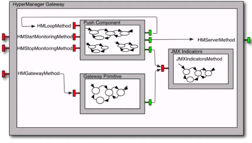
3.3.1 On HyperManager Gateway . . . 48
3.3.2 On HyperManager Server . . . 56
3.3.3 On System Product . . . 58
3.4 The case study reloaded: on structural reconfigurations . . . 61
3.4.1 On HyperManager Reconfigurable Gateway . . . 61
3.4.2 On HyperManager Reconfigurable Server . . . 62
3.4.3 On Reconfigurable System Product . . . 63
3.5 Discussion . . . 65
4 A mechanized framework for reasoning on software architectures 67 4.1 Mechanizing GCM with the Coq proof assistant . . . 68
4.1.1 Core elements . . . 69
4.1.2 Well-formed component architectures . . . 76
4.1.3 Well-typed component architectures . . . 83
4.1.4 Well-formedness and well-typedness decidability . . . 86
4.2 An operation language for composing architectures . . . 98
4.2.1 Syntax and semantics . . . 99
TABLE OF CONTENTS xv
4.3 Proving Properties . . . 108
4.3.1 Meeting the Specification: Absence of Cross-Bindings . . . . 108
4.3.2 Supporting Parametrized ADLs . . . 110
4.3.3 Structural Reconfigurations . . . 111
4.4 Discussion . . . 115
5 Painless integration with ProActive 119 5.1 Integration approach . . . 120
5.1.1 Computing states from operations . . . 121
5.1.2 Certified code, Painless interpreter, and the ProActive mid-dleware . . . 123
5.2 The Painless architecture description language . . . 126
5.2.1 Painless Semantics . . . 128
5.2.2 Painless hello world and beyond . . . 129
5.3 Discussion . . . 132
6 Mechanized behavioural semantics 135 6.1 Groundwork: Infinite data structures . . . 136
6.2 Labelled transition systems, and traces . . . 137
6.2.1 Encoding labelled transitions systems . . . 137
6.2.2 LTS traces . . . 138
6.3 Synchronization of LTS, and traces . . . 140
6.3.1 Encoding synchronizations between LTSs . . . 141
6.3.2 Net traces . . . 142
6.3.3 Synchronized Master & Slave example . . . 147
6.4 Towards GCM behavioural models . . . 154
6.5 Discussion . . . 159
7 Related work 161 7.1 On the HyperManager use case . . . 162
7.2 On the Mefresa framework . . . 163
8 Final remarks 167
8.1 Perspectives . . . 168
A Résumé de la thèse 171 A.1 Introduction . . . 171
A.1.1 Génie logiciel à base de composants . . . 171
A.1.2 Contexte — Le projet Spinnaker . . . 172
A.1.3 Contributions . . . 173
A.1.4 Organisation de cette thèse . . . 174
A.2 Conclusion . . . 175
Bibliography 177
List of Figures
2.1 A simple GCM architecture . . . 9 2.2 Normal Binding . . . 11 2.3 Import Binding . . . 11 2.4 Export Binding . . . 11 2.5 Components A and B . . . 15 2.6 A invokes f1 from B . . . 15 2.7 A blocks! wait-by-necessity . . . 162.8 B replies, and A is happy . . . 16
2.9 Simple GCM application example . . . 17
2.10 GCM composite application example . . . 18
2.11 pNet representing a primitive component . . . 22
2.12 Behaviour of proxy . . . 23
2.13 Behaviour of the proxy manager . . . 23
2.14 Binding controller . . . 24
2.15 pNet example for reconfigurable multicast interface . . . 25
3.1 Hierarchical representation of our case study . . . 41
3.2 HyperManager server component . . . 42
3.3 HyperManager gateway component . . . 43
3.4 Formal specification and verification workflow . . . 46
3.5 Behaviour of the JMXIndicatorsMethod method . . . 50
3.6 Behaviour of the HMGatewayMethod method . . . 52 xvii
3.7 Behaviour of the HMStartMonitoringMethod method . . . 53
3.8 Behaviour of the HMStopMonitoringMethod method . . . 53
3.9 Behaviour of the HMLoopMethod method for the HyperManager Gateway . . . 53
3.10 Behaviour of the HMServerMethod method . . . 56
3.11 Behaviour of the HMLoopMethod method for the HyperManager Server . . . 57
4.1 binding examples . . . 73
4.2 Use-Case Architecture . . . 112
4.3 Mefresa overview from a GCM perspective . . . 116
5.1 Overall integration of Painless with ProActive . . . 126
5.2 starter application . . . 130
5.3 composite application . . . 130
6.1 LTS of a queue, bounded by two requests . . . 155
List of Listings
2.1 GCM/ProActive slave component ADL . . . 17
2.2 GCM/ProActive Composite component ADL . . . 18
2.3 GCM/ProActive Master component ADL . . . 19
2.4 The Order type . . . 26
2.5 The Slave process (part 1/2) . . . 26
2.6 The Slave process (part 2/2) . . . 27
2.7 The Master process . . . 28
2.8 Process synchronization . . . 28
2.9 nat datatype . . . 30
2.10 list datatype . . . 30
2.11 plus function definition . . . 31
2.12 length function definition . . . 32
2.13 option datatype . . . 32
2.14 head function definition . . . 32
2.15 vector datatype . . . 33
2.16 vhead function definition . . . 33
2.17 is_even predicate definition . . . 33
2.18 Proof that 4 is even . . . 34
2.19 permut predicate definition . . . 34
2.20 Permutation proof example . . . 36
2.21 original vhead function . . . 37
2.22 Extracted vhead function . . . 37 xix
3.1 Queue specification of the JMX Indicators component in Fiacre (bounded
at two requests) . . . 43
3.2 Body specification of the JMX Indicators component in Fiacre . . . . 45
3.3 Specification for the JMXIndicatorsMethod argument and return types 48 3.4 JMXIndicatorsMethod specification . . . 49
3.5 HMGatewayMethod specification . . . 51
4.1 interface datatype . . . 69
4.2 ident, signature and path datatypes . . . 69
4.3 role datatype . . . 70
4.4 contingency datatype . . . 70
4.5 Boolean equality function for the role datatype values . . . 70
4.6 component datatype . . . 71
4.7 Projection for the component identifier element . . . 71
4.8 Function to find a component by its identifier . . . 72
4.9 binding datatype . . . 72
4.10 binding examples in Mefresa . . . 73
4.11 Model for component "Component N" (part 1 of 3) . . . 73
4.12 Model for component "Component N" (part 2 of 3) . . . 74
4.13 Model for component "Component N" (part 3 of 3) . . . 75
4.14 well-formed component definition . . . 76
4.15 unique_ids predicate definition . . . 76
4.16 well_formed_interfaces predicate definition . . . 77
4.17 Function to find an interface by its identifier and visibility values . . . 78
4.18 well_formed_bindings predicate definition . . . 79
4.19 normal_binding predicate definition . . . 79
4.20 export_binding predicate definition . . . 80
4.21 Proof script for the C_is_well_formed Lemma . . . 81
4.22 well_typed predicate definition . . . 83
4.23 sound_contingency predicate definition . . . 83
4.24 client_internal_mandatory_itfs_are_bound predicate definition . . . . 84
4.25 subc_client_external_mandatory_itfs_are_bound predicate definition 84 4.26 decidable predicate definition . . . 87
LIST OF LISTINGS xxi 4.27 well_typed_bool function definition . . . 93 4.28 sound_contingency_bool function definition . . . 93 4.29 client_internal_mandatory_itfs_are_bound_bool function definition . 93 4.30 client_internal_mandatory_itfs_are_bound_bool_one function
defi-nition . . . 94 4.31 check_if_recipients_are_mandatory_aux function definition . . . 94 4.32 state datatype . . . 99 4.33 operation datatype . . . 99 4.34 Notation for sequence of operations . . . 100 4.35 Reflexive transitive closure definition of step . . . 102 4.36 operation for the component "Component N" . . . 103 4.37 operation for the component "C" . . . 104 4.38 operation for the component "S" . . . 104 4.39 operation for binding the components . . . 104 4.40 Overall operation for component "Compoennt N" . . . 105 4.41 Logical statement regarding the reduction of build_running_example 105 4.42 well_formed predicate definition . . . 106 4.43 validity statement . . . 107 5.1 Excerpt of the build_state function definition . . . 121 5.2 validity statement . . . 122 5.3 wf_error_msg type definition . . . 123 5.4 custom_build_state function definition . . . 124 5.5 custom_build_state_correct lemma . . . 125 5.6 Shorthand for interfaces . . . 127 5.7 Role symmetry . . . 128 5.8 Interface symmetry . . . 128 5.9 A first Painless specification . . . 130 5.10 Painless specification for the composite tutorial . . . 130 5.11 Painless reconfigurations . . . 131 6.1 LList datatype . . . 136 6.2 Lazy list holding all natural numbers . . . 137 6.3 lts_state datatype . . . 137
6.4 action datatype . . . 137 6.5 message datatype . . . 138 6.6 LTS datatype . . . 138 6.7 Trace definition for a LTS . . . 139 6.8 lts_target_state function definition . . . 139 6.9 SynchronizationVector datatype . . . 141 6.10 A convenient notation for SynchronizationVector . . . 141 6.11 Net datatype . . . 142 6.12 net_state datatype . . . 142 6.13 net_target_states function definition . . . 142 6.14 init_net_state function . . . 144 6.15 attainable predicate definition . . . 145 6.16 Trace definition for Net . . . 146 6.17 Definition of the satisfies predicate . . . 147 6.18 Definition of the Always predicate . . . 147 6.19 Definition of the slave process lts_states . . . 148 6.20 Definition of the slave process actions . . . 148 6.21 Definition of the slave process transitions . . . 149 6.22 Definition of the slave process LTS . . . 149 6.23 Definition of the master process lts_states . . . 149 6.24 Definition of the master process actions . . . 149 6.25 Definition of the master process transitions . . . 150 6.26 Definition of the master process LTS . . . 150 6.27 Definition of the master process LTS . . . 150 6.28 Definition of the overall Net . . . 150 6.29 Definition of the interleaving predicate . . . 151 6.30 Definition of the Rma relation . . . 151 6.31 Definition of the Rma relation . . . 154 6.32 Encoding of the lts_states for the queue process . . . 155 6.33 Encoding of the transitions for the queue process . . . 155 6.34 Encoding of the initial lts_state for the queue process . . . 155 6.35 Encoding of the queue process . . . 156 6.36 Encoding of the body transitions . . . 156
LIST OF LISTINGS xxiii 6.37 Remaining definitions encoding body process . . . 157 6.38 Encoding of JMX Indicators method . . . 157 6.39 Encoding of the component system . . . 158 6.40 Definition of the recursive Net datatype . . . 159
List of Tables
2.1 Rules for the permut predicate . . . 35 3.1 State-space information for the HyperManager Gateway component . 54 3.2 State-space information for the HyperManager Server component . . 57 3.3 State-space information for the overall system product . . . 59 3.4 State-space information for HyperManager Gateway with
reconfig-urable interface . . . 62 3.5 State-space information for HyperManager Server with reconfigurable
interface . . . 62 3.6 State-space information for the reconfigurables HyperManager Server
and HyperManager Gateway . . . 63 3.7 State-space information for the reconfigurables HyperManager Server
and HyperManager Gateway (second approach) . . . 64 4.1 Semantics of our operation language . . . 101 4.2 Details regarding the number of lines composing Mefresa . . . 117 5.1 Painless syntax (excerpt) . . . 127 5.2 Painless semantic rules (excerpt) . . . 128
Chapter
1
Introduction
"Never permit a dichotomy to rule your life, a dichotomy in which you hate what you do so you can have pleasure in your spare time. Look for a situation in which your work will give you as much
happiness as your spare time."
Pablo Picasso
Contents
1.1 Component-based software engineering . . . . 2 1.2 Context — The Spinnaker project . . . . 3 1.3 Contributions . . . . 3 1.4 Organisation of this thesis . . . . 4 This thesis belongs to the domain of formal methods. In particular, we focus on their application to a specific methodology for the development of software: component-based engineering.
Either by means of automatic or interactive approaches, the goal of formal methods is to increase the confidence one can place on a software system. Through-out this thesis, we discuss the application of formal methods techniques in the
context of component-based engineering.
1.1 Component-based software engineering
Among all programming paradigms, component-based engineering stands as one of the most followed approaches for real world software development. Its emphasis on a clean separation of concerns makes it appealing for both industrial and research purposes. Furthermore, component-based systems are notorious for their capacity to address the inherent challenges of today’s software development. They promote modular designs, and therefore ease the burden of development and maintenance of applications. Moreover, portability and re-usability of components are further benefits of this paradigm.
There are several component models proposed in the literature [1, 2, 3], each with their own particularities (hierarchical/flat, static/reconfigurable, ...). Yet, their foundation is generally made of three main ingredients: components,
inter-faces, and bindings. A component can be seen as a building block, usually a piece
of software code. An interface is an access point to/from components. Finally, a binding is a connection established between components, through their interfaces. Indeed, component-based programming shares some resemblances with object-oriented programming. Their fundamental distinction lies in the fact that in the former paradigm, communications are always explicitly made through the compo-nent’s interfaces, therefore making all existing dependencies evident.
Another facet of component-based systems concerns software evolution. This methodology of developing software enables on-the-fly structural reconfigurations of the architecture of the application. The advantage of modifying the software architecture at runtime comes from the need to cope with the plethora of situations that may arise in a potentially massively distributed and heterogeneous system. Indeed, the ability to restructure is also a key aspect in the field of autonomic computing where software is expected to adapt itself. However, this capacity comes with a price: we no longer need only to care about functional concerns, but also about structural ones.
The widespread use of component models together with the interesting chal-lenges posed by reconfigurable component-based applications make it an exciting
1.2. CONTEXT — THE SPINNAKER PROJECT 3 research topic for the formal methods community. Within our research group, we focus on the Grid Component Model (GCM) [2] to address the intricacies of grid and cloud computing. Details regarding its specification are discussed in Section 2.1.
1.2 Context — The Spinnaker project
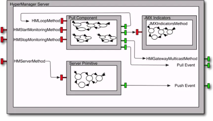
This thesis occurs in the context of the Spinnaker project1, a collaborative project between INRIA and several industrial partners, where we intend to contribute for the widespread adoption of Radio-Frequency Identification (RFID)-based technol-ogy. To this end, our contribution comes with the design and implementation of a non-intrusive, flexible and reliable solution that can integrate itself with other already deployed systems. Specifically, we developed The HyperManager, a general purpose monitoring application with autonomic features. This was built using GCM/ProActive2— a Java middleware for parallel and distributed program-ming that follows the principles of the GCM. For the purposes of this project, it had the goal to monitor the E-Connectware3 (ECW) framework in a loosely coupled manner.
1.3 Contributions
In this thesis, we contribute to the state of the art in the domain of formal methods and (distributed) component-based systems.
Our first contribution is an industrial case study on the behavioural specifica-tion and verificaspecifica-tion of a reconfigurable distributed applicaspecifica-tion. This promotes the use of formal methods in an industrial context, but also puts in evidence the neces-sity for alternative and/or complementary approaches in order to better address such undertakings.
Our second contribution is a framework, developed with the Coq proof as-sistant, for reasoning on software architectures: Mefresa. This encompasses
1Project OSEO ISIS. http://www.spinnaker-rfid.com/ 2http://proactive.activeeon.com/index.php
the mechanization of the GCM specification, and the means to reason about re-configurable GCM architectures. Further, we address behavioural concerns by formalizing a semantics based on execution traces of synchronized transition sys-tems. Overall, it provides the first steps towards a complete specification and verification platform addressing both architectural and behavioural properties.
Finally, our third contribution is a new Architecture Description Language (ADL), denominated Painless, and its proof-of-concept integration with the ProActive middleware. Painless allows to specify parametrized GCM architec-tures, along with their structural reconfigurations, in a declarative-like language. Compliance with the GCM specification is evaluated by certified functional code extracted from Mefresa. This permits the safe deployment and reconfiguration of GCM applications.
The following publications resulted from this thesis.
• Nuno Gaspar and Eric Madelaine. Fractal à la Coq. Conférence en Ingénierie du Logiciel, Rennes, France, June 2012.
• Nuno Gaspar, Ludovic Henrio and Eric Madelaine. Bringing Coq into the
World of GCM Distributed Applications. International Journal of Parallel
Programming, August 2014. Volume 42, Issue 4, pp 643-662.
• Nuno Gaspar, Ludovic Henrio and Eric Madelaine. Formally Reasoning on a
Reconfigurable Component-Based System — A Case Study for the Industrial World. International Symposium on Formal Aspects of Component Software
(FACS’2013). Lecture Notes in Computer Science 2014, pp 137-156.
• Nuno Gaspar, Ludovic Henrio and Eric Madelaine. Painless support for the
static and runtime verification of component-based applications. (submitted)
Moreover, a talk entitled Formal Reasoning on Component-Based
Reconfig-urable Applications, was given at the student session of the 40th ACM
SIGPLAN-SIGACT Symposium on Principles of Programming Languages (POPL’2013).
1.4 Organisation of this thesis
1.4. ORGANISATION OF THIS THESIS 5 • Chapter 2 gives an overview of the technical background required for the understanding of this thesis. Pointers for relevant literature are indicated for the reader desiring further details.
• Chapter 3 discusses an industrial case study on the formal specification and verification of a reconfigurable GCM/ProActive application. This is achieved by formally defining its behavioural semantics and check it against the desired properties by means of model-checking techniques.
• Chapter 4 presents Mefresa, a framework for the reasoning on
soft-ware architectures. It is tailored for the GCM, and developed using the
Coq proof assistant.
• Chapter 5 shows how we leverage the Mefresa framework and Coq’s certi-fied extraction mechanism to provide an extension to the
GCM/ProAc-tive middleware. Further, we propose Painless, a novel language for the
specification of reconfigurable GCM architectures.
• Chapter 6 addresses the mechanization of a behavioural semantics using
the Coq proof assistant. We show how we can interactively reason about
transition systems. Further, we illustrate its use in the context of the GCM. • Chapter 7 discusses relevant related work w.r.t. to the main contributions
of this thesis.
• For last, chapter 8 discusses the final conclusions about this thesis, and indicates perspectives for future work and improvements.
Chapter
2
Preliminaries
“We live in a society exquisitely dependent on science and
technology, in which hardly anyone knows anything about science and technology."
Carl Sagan
Contents
2.1 The GCM Component Model . . . . 8
2.1.1 Overview of the GCM specification . . . 9 2.1.2 The GCM ADL . . . 12
2.2 ProActive — A middleware for distributed program-ming . . . . 14
2.2.1 GCM/ProActive — a reference implementation for GCM 15 2.2.2 Specifying architectures with the ADL . . . 16
2.3 pNets: A formalism for defining behavioural semantics 20
2.3.1 Behavioural semantics for GCM/ProActive applications 22 2.3.2 Coping with structural reconfigurations . . . 23
2.4 The Fiacre specification language . . . . 25 7
2.5 A brief overview of the Coq Proof Assistant . . . . 29
2.5.1 Data types . . . 29 2.5.2 Functional programming in Coq . . . 31 2.5.3 Proving properties . . . 33 2.5.4 Extracting certified programs . . . 36
This chapter discusses the required background for the reading of this thesis. Each of its constituents Sections are self-contained presentations to relevant ma-terial for its understanding. The reader already familiar with some of the Sections may opt to skip them.
Section 2.1 introduces the GCM component model. Its reference implemen-tation is discussed in Section 2.2. Then, Section 2.3 presents a formalism for specifying behavioural semantics. Section 2.4 discusses the Fiacre specification language. For last, Section 2.5 provides an overview of the Coq proof assistant.
2.1 The GCM Component Model
Proposed by the CoreGrid European network of Excellence, the GCM [2] is based on the Fractal Component Model [1], with extensions addressing the issues of grid computing: deployment, scalability and asynchronous communications. Essen-tially, it benefits from Fractal’s hierarchical structure, introspection capabilities, extensibility, and the separation between interfaces and implementation. In the following, we do not discriminate what is inherited from the Fractal component model and what is an extension. We discuss the whole features defining the GCM. The main objectives of the GCM are the implementation, deployment, and management of complex and distributed systems. Indeed, there are several pro-posals for component models in the literature, yet, most suffer from limited support for extension, adaptation, and distribution. To this end, the GCM offers customiz-able communication patterns, transparent remote component access, component composition, introspection (i.e. monitoring of the running system), and (auto-nomic) (re)configuration capabilities. Moreover, the GCM intends to be suited for a wide range of application scenarios.
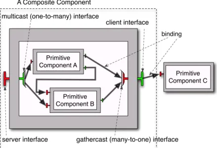
2.1. THE GCM COMPONENT MODEL 9 Primitive Component A Primitive Component B Primitive Component C binding server interface client interface multicast (one-to-many) interface
gathercast (many-to-one) interface A Composite Component
Figure 2.1: A simple GCM architecture
An example of a GCM architecture is depicted by Figure 2.1. Basically, the core elements of a GCM application are (1) components, which can be composite or primitive — depending on whether they have inner components or not —, (2)
interfaces, and (3) bindings. As expected, interfaces act as access points, and
bindings establish communications between components.
Both synchronous and asynchronous communications are supported. These, can be one-to-one, but also of collective nature: one-to-many (multicast),
many-to-one (gathercast), and even many-to-many. Moreover, support for autonomic
aspects are provided by means of non-functional interfaces.
In the remainder of this section we delve into the GCM intricacies and further discuss its characteristics that are relevant for the understanding of this thesis. For more details the interested reader is pointed to the GCM’s technical specification [4].
2.1.1 Overview of the GCM specification
Component introspection In the GCM, components are endowed with
hierarchical component model is the possibility to adjust the granularity of ab-straction, i.e. components can be seen as white or black boxes. As a black box, one cannot see its internal structure, solely its external interfaces.
Each interface has a name. All external interfaces of one component must have distinct names, but no such restriction is imposed on interfaces belonging to different components. Moreover, an interface is also characterized by its role: it can be a client or server interface. The former emits operation invocations, while the latter receives them. Intuitively, one should see the client interfaces as the means for service methods to interact with other service methods.
Component’s interfaces can be introspected through two different Application Programming Interface (API)s: the Component interface, and the Interface inter-face. The former specifies the methods getFcInterfaces() and getFcInterface(String iftName), that return an array of references to the component’s interfaces, and a reference to the interface whose name matches the value itfName passed as ar-gument, respectively. The latter, focuses on the introspection from an interface perspective. In particular, it specifies a getFcItfName() method, that returns a string with the name of the interface, and getFcItfOwner(), that returns the Com-ponent reference of the comCom-ponent to which it belongs.
Component configuration A GCM component, primitive or composite, is
ar-ranged by two parts: a membrane and a content. The former — see the grey parts of each component of Figure 2.1 — contains a set of controllers that expose non-functional interfaces. These allow to dynamically reconfigure the structure of a GCM application. The latter, is either an object — for primitive components — or a finite set of subcomponents — for composite components —, which are under control of the enclosing component’s controllers.
A membrane can have interfaces of external and internal visibility. External interfaces are available from outside the component, while internal interfaces are accessible to the component’s direct subcomponents. A component’s interfaces can share the same name provided they have a different visibility. Moreover, interfaces are also classified regarding their functionality: they can be functional or control. The former corresponds to an interface providing or requiring a functionality to the component. Intuitively, it means it is part of the application logic. The
2.1. THE GCM COMPONENT MODEL 11 latter provides "non-functional" aspects, such as reconfiguration capabilities. This capacity to reconfigure the application’s architecture at runtime is of paramount importance, and plays a key role in the realm of autonomic computing.
A binding is a communication path from a client interface to a server interface. There are three types of bindings. A normal binding (1) is established between two external interfaces from components at the same hierarchical level, i.e. pos-sessing the same enclosing component. An import binding (2) is made from a (sub)component to its enclosing component. Last, an export binding (3) binds a component to one of its subcomponents. For the sake of clarity, these are depicted by Figure 2.2, Figure 2.3, and Figure 2.4, respectively.
S
C
X C S Figure 2.2: Normal BindingC
S C S Figure 2.3: Import BindingS
C s c Figure 2.4: Export BindingThis can be seen as a structural constraint ensuring that no binding can "cross" a component boundary except through its interfaces. Further, a client interface can be bound to at most one server interface, while several client interfaces can be bound to the same server interface. This constraint is relaxed if the client interface is of multicast cardinality. Other cardinality values include singleton, for simple one-to-one communications, and gathercast that act as a rendez-vous for gathering data.
Component runtime instantiation In the GCM, component creation is achieved
through factories. Basically, components are created by other special type of com-ponents called component factories.
The GCM offers a generic component factory and a standard component fac-tory. The former allows the creation of several kinds of components, while the latter is more specific, it can only create components of the same type. For both factories, one can wonder: if components are created from component factories,
how are component factories created? From other component factories? Indeed,
this would lead to an infinite recursion. This is solved by the inclusion of a
boot-strap component factory that needs not to be created explicitly. Naturally, it is
able to create several kinds of components, namely component factories.
Component typing A simple type system is defined for composing components.
It mainly reflects the characteristics of the component’s interfaces. In particular it focuses on the cardinality and contingency attributes of an interface.
There are four possible values for an interface cardinality. Considering an in-terface of type T, it can be singleton (1), entailing that the component owning it must have exactly one interface of type T. Collection (2), indicating that an arbitrary number of interfaces of type T can coexist on a given component. How-ever, their name must begin with the same name specified in T. Since there is an infinite number of such interfaces, they cannot be created at the same time, they must be created lazily, i.e., at invocation time. An interface may also be multicast (3): it is like a singleton, but transforms each invocation into a set of invocations. At last, an interface of gathercast (4) cardinality also behaves as a singleton, but transforms a list of invocations into a single invocation.
Regarding the interface’s contingency attribute, an interface can be optional or mandatory. The operations of an optional interface are not guarantee to be available at runtime, while a mandatory interface provides such guarantee. Ba-sically, mandatory interfaces are made for components absolutely requiring other components to work, whereas optional interfaces are useful for components that may use others, if present. For instance, a parser component absolutely needs a lexer component, but can work with or without a logger component.
2.1. THE GCM COMPONENT MODEL 13
2.1.2 The GCM ADL
One may need to define arbitrarily complex architectures. With the increase of complexity in the system to be described, it is important to have a precise way to describe such architectures. In the realm of component-based engineering, this is usually achieved by means of an ADL. The GCM follows this approach by supporting its own GCM ADL [5].
The GCM ADL is a XML-based language. As a root element it contains the
definition element. Basically, it describes the structure of the application via component, interface and binding elements. The component element possesses
a name and definition attribute. These identify the component, and its owner, respectively. Moreover, it may contain the following child elements:
• comment: a free form of text documenting the component. (0-unlimited); • interface: description of the interface provided by the component. (0-unlimited); • component: reference to a subcomponent. (0-unlimited);
• binding: description of the binding hold by the component. (0-unlimited); • content: class which represents the components. (0-1);
• attributes: list of attributes of the component. (0-1); • controller: controller of the component. (0-1);
• virtualNodes: list of virtual nodes the component should be deployed on. (0-1);
• exportVirtualNodes: list of export virtual nodes. (0-1) .
A comment element is a simple text element, adding some contextual information. An interface element possesses the following attributes:
• name: identifier of the interface. (required); • role: ’client’ or ’server’. (required);
• signature: signature of the interface. (required); • contingency: ’mandatory’ or ’optional’. (optional);
• cardinality: ’singleton’, ’collection’, ’gathercast’ or ’multicast’. (optional); • comment: a free form of text documenting the interface. (0-unlimited). Its constituting attributes should pose no doubt. However, the careful reader may notice that there is no attribute specifying whether an interface is of internal or external visibility. This must be handled in an automated manner. For instance, a multicast server interface of a composite component is in fact the composition between a server interface and a multicast internal client interface.
Next, the component child element of the component element portrays GCM’s hierarchical nature. The binding element is solely composed by two attributes,
client and server, which hold the name of the client and server interfaces involved
in the binding, respectively. The content element features solely the class attribute that specifies the class implementing the component.
The attributes element are key/value pairs that can be used to parametrize the component. The controller element indicates the component controller that manages the component w.r.t. non-functional aspects. Finally, the remaining elements virtualNodes and exportVirtualNodes serve the purpose of facilitating the deployment task, i.e., one may want to distribute its application to a set of predefined nodes.
This Subsection discussed the main ingredients of the GCM ADL. For a more detailed description of its intricacies, namely its XML schema, the interested reader is pointed to its technical specification [5].
2.2 ProActive — A middleware for distributed
programming
ProActive1 is an open source Java middleware for the programming of multi-threaded, parallel, and distributed applications. An application adopting
2.2. PROACTIVE — A MIDDLEWARE FOR DISTRIBUTED PROGRAMMING15 tive is composed by entities denominated active objects [6]. Each active object contains a distinguished element, the root, that is its only entry point. Moreover, it possesses its own thread of control, every incoming method call is automatically placed in a queue of pending requests, and is able to decide by which order it serves them.
Further, incoming method calls are asynchronous with transparent future ob-jects. Basically, a short rendezvous occurs at the beginning of each asynchronous remote call, which blocks the caller until the call has reached the callee. Then, if the invoked method returns a result, a future object is created on the callee side and returned back as a result to the caller. Thus, a future can be seen as a placeholder for the return value of an active object method invocation. The object that issued the invocation can therefore proceed its execution. At a later stage, if it needs to read the actual returned value, it blocks until the value is available — i.e. until the request is processed and returned back from the callee — or continues transparently if meanwhile the value has already been obtained. This mechanism is called wait-by-necessity.
Another common nomenclature found in the literature for the future concept is promise [6]. Both terms are often used interchangeably.
2.2.1 GCM/ProActive — a reference implementation for
GCM
As mentioned earlier, ProActive is the de facto reference implementation for GCM. For this reason, whenever focusing on its component model part, it is often referred to by GCM/ProActive.
In GCM/ProActive a primitive component is implemented through an active object, and thus includes its standard features. Components communicate asyn-chronously through the established bindings between their interfaces.
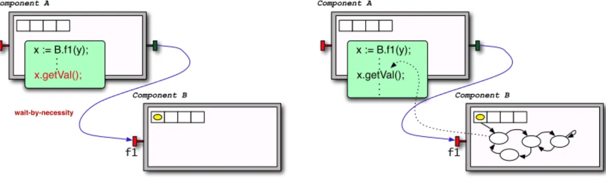
For instance, let us consider two components of some architecture as depicted by Figure 2.5. Components A and B both possess a server interface (in red), and the former is also equipped with a client interface (in green). A binding between
A’s client interface and B’s server interface connects them together. Moreover,
Component A
Component B
f1
Figure 2.5: Components A and B
Component A Component B f1 x := B.f1(y); . ..
Figure 2.6: A invokes f1 from B
Whenever A invokes the method f1 from B’s server interface, a request is inserted into B’s queue. At this point, the variable x holds a future for the reply of f1, and A proceeds its execution (Figure 2.6).
Component A Component B f1 x := B.f1(y); . .. x.getVal(); wait-by-necessity
Figure 2.7: A blocks! wait-by-necessity
Component A Component B f1 x := B.f1(y); . .. x.getVal(); .. .
Figure 2.8: B replies, and A is happy
If A needs to access the value of x, then it may be the case that B has not yet treated the request, and thus A blocks until it gets the reply from f1’s invocation (Figure 2.7). Alternatively, it may be the case that B already replied, and therefore
A can proceed its execution transparently (Figure 2.8).
As expected, GCM components are mono-threaded, i.e. only one request is treated at a time. It may seem restrictive, but it has the benefit of ensuring thread-safety. Nevertheless, we may refer that recent work aims at improving performance by allowing multi-threading for active objects [7].
2.2. PROACTIVE — A MIDDLEWARE FOR DISTRIBUTED PROGRAMMING17
2.2.2 Specifying architectures with the ADL
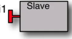
As discussed in Subsection 2.1.2, the GCM defines its ADL as a means to specify component architectures. GCM/ProActive includes support for such feature. For instance, let us consider the simple GCM application depicted by Figure 2.9.
Slave
i1
Figure 2.9: Simple GCM application example
It is composed solely by one primitive component, named Slave, possessing one server interface named i1. Listing 2.1 illustrates the specification of this architec-ture.
1 <!DOCTYPE d e f i n i t i o n PUBLIC " −//objectweb . org //DTD Fractal ADL 2.0//
EN" " c l a s s p a t h :// org / objectweb / p r o a c t i v e / core /component/ adl /xml/ p r o a c t i v e . dtd ">
2 <d e f i n i t i o n name=" org . objectweb . p r o a c t i v e . examples . userguide .
components . adl . s t a r t e r . adl . Slave ">
3 <interface s i g n a t u r e=" org . objectweb . p r o a c t i v e . examples . userguide .
components . adl . s t a r t e r . I t f 1 " r o l e=" s e r v e r " name=" i 1 ">
4 <content c l a s s=" org . objectweb . p r o a c t i v e . examples . userguide . components
. adl . s t a r t e r . SlaveImpl "/> 5 <controller desc=" p r i m i t i v e "/> 6 </d e f i n i t i o n>
Listing 2.1: GCM/ProActive slave component ADL
The contents of the ADL should pose no doubt. Line 1 concerns XML validation aspects, basically it allows standard validators to check if the XML file is well formed. The component architecture aspects per se begin at line 2. Its definition possesses the name attribute indicating its classpath, and contains three child elements: interface, content and controller. The interface’s signature points to the
java interface file holding signature for the supported service methods. Next, it is
specified as having a server role and with name i1 (line 3). The content holds the
i.e. it implements the service methods specified in the interface’s signature (line 4). At last, the controller specifies the default primitive component controller (line 5). Moreover, no information is provided regarding virtual nodes. This is usually the case when deploying the application locally.
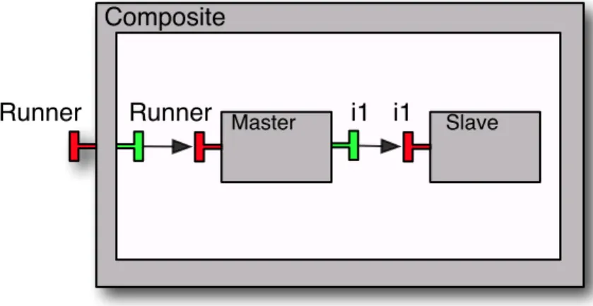
Let us now look at a more elaborated example. Figure 2.10 depicts a slightly more complex architecture featuring three components: Composite, Master and the previously discussed Slave.
Slave i1 Master Runner i1 Runner Composite
Figure 2.10: GCM composite application example
The Composite encapsulates the two remaining components and exposes one ex-ternal server named Runner. Its symmetric counterpart, i.e. inex-ternal and client, is bound to the server interface of the Master component, also named Runner. Further, the Master component is also equipped with a client interface named i1 that is bound to the Slave’s server interface. Listing 2.2 shows its ADL.
1 <!DOCTYPE d e f i n i t i o n PUBLIC " −//objectweb . org //DTD Fractal ADL 2.0//
EN" " c l a s s p a t h :// org / objectweb / p r o a c t i v e / core /component/ adl /xml/ p r o a c t i v e . dtd ">
2
3 <d e f i n i t i o n name=" org . objectweb . p r o a c t i v e . examples . userguide .
components . adl . composite . adl . Composite ">
4 <interface s i g n a t u r e=" org . objectweb . p r o a c t i v e . examples . userguide .
components . adl . composite . Runner " r o l e=" s e r v e r " name=" runner "/> 5
6 <component name=" Master " d e f i n i t i o n=" org . objectweb . p r o a c t i v e .
2.2. PROACTIVE — A MIDDLEWARE FOR DISTRIBUTED PROGRAMMING19
7 <component name=" Slave " d e f i n i t i o n=" org . objectweb . p r o a c t i v e .
examples . userguide . components . adl . composite . adl . Slave "/> 8
9 <binding c l i e n t=" t h i s . runner " s e r v e r=" Master . runner "/> 10 <binding c l i e n t=" Master . i 1 " s e r v e r=" Slave . i 1 "/>
11
12 <controller desc=" composite "/> 13 </d e f i n i t i o n>
Listing 2.2: GCM/ProActive Composite component ADL
Line 3 starts the definition of this Composite by indicating its classpath, and including the child elements relevant for this specification. As mentioned above, the GCM ADL does not include an attribute for specifying whether an interface is of external or internal visibility. Indeed, there is only one interface element included in the composite ADL (line 4). Its symmetric counterpart is not specified and automatically handled by GCM/ProActive. Next, the component elements at lines 6 and 7 are references to their actual ADLs. Lines 9 and 10 specify the two bindings of this architecture using the familiar this and . notations. For last, line 12 specifies the controller as the default composite component controller.
The remaining pieces for the specification of the Composite architecture con-cerns the ADLs of its two subcomponents: Master and Slave. The Slave architec-ture has already been discussed (see Listing 2.1), its only modification concerns the classpath of its name definition. Regarding the Master component, its ADL is depicted by Listing 2.3.
1 <!DOCTYPE d e f i n i t i o n PUBLIC " −//objectweb . org //DTD Fractal ADL 2.0//
EN" " c l a s s p a t h :// org / objectweb / p r o a c t i v e / core /component/ adl /xml/ p r o a c t i v e . dtd ">
2
3 <d e f i n i t i o n name=" org . objectweb . p r o a c t i v e . examples . userguide .
components . adl . composite . adl . Master ">
4 <interface s i g n a t u r e=" org . objectweb . p r o a c t i v e . examples . userguide .
components . adl . composite . Runner " r o l e=" s e r v e r " name=" runner "/> 5 <interface s i g n a t u r e=" org . objectweb . p r o a c t i v e . examples . userguide .
components . adl . composite . I t f 1 " r o l e=" c l i e n t " name=" i 1 "/> 6
components . adl . composite . MasterImpl "/> 8
9 <controller desc=" p r i m i t i v e "/> 10 </d e f i n i t i o n>
Listing 2.3: GCM/ProActive Master component ADL
As expected, it follows the same structure as the Slave ADL. Indeed, it mainly differs on the inclusion of a client interface (line 5).
In this Section we only covered the fundamentals of the ProActive middleware. The interested reader is pointed to ProActive’s programming manual for more discussion on its intricacies [8].
2.3 pNets: A formalism for defining behavioural
semantics
pNets stands for parametrized Network of synchronized automata. It provides an
intermediate and general formalism aimed at the specification and synchronisa-tion of the behaviour of a set of automata. Further, it is mainly aimed towards two goals: provide a formal foundation to the model generation principles for distributed component frameworks — such as GCM —, and to propose an expres-sive, yet concise, machine-oriented model that can be used as an internal format for software tools.
The first definition of pNets was published in [9]. Here, we restrict ourselves to a more succinct discussion, focusing on the material relevant for the understanding of this thesis.
A pNet is a hierarchical structure whose leaves are pLTSs or queues. A pLTS is a labelled transition system with variables. It can possess guards and assignments on its transitions. It is formally defined as follows.
Definition 2.3.1 (pLTS). A pLTS is a parametrized LTS defined by a tuple
pLT S� (P, S, s0, L,→) where
• P is a finite set of parameters, from which we construct the term algebra
TP, with parametrized actions AP, the parametrized expression EP, and the
2.3. PNETS: A FORMALISM FOR DEFINING BEHAVIOURAL SEMANTICS21
• S is a set of states. For each state s ∈ S, variables of s are global to the pLTS.
• s0 ∈ S is the initial state.
• L is the set of labels of the form (–,eb,(xj ∶= ej)j∈J), where – ∈ AP is a
parametrized action, eb∈ BP is a guard, and the variables xj ∈ P are assigned
the expressions ej ∈ EP.
• →⊆ S × L × S is the transition relation.
Before proceeding to the remaining definition of a pNet structure, let us define the sort of a pNet. Basically, it is its signature: the set of actions it can perform, that is, the set of labels of its transitions. We define it by the following function
Sort∶ pNet → AP.
Sort(p) =�������
����� �
L for p = (P, S, s0, L,→)
{?Q_mi � mi∈ M} ∪ {!Serve_mi � mi∈ M} for p = Queue(M)
L for p = (P, L, pNetk∈K
i , SVkk∈K)
Its definition should pose no doubt. For the cases of being a leaf, if it is either a pLTS or a queue. For the former it simply returns its set of labels L. For the latter it returns a set of actions depending on M ⊆ TP. Basically, a Queue(M) can be
seen as an infinite pLTS modelling the behaviour of a First In, First Out (FIFO) queue. Its semantics is simply the en-queueing and de-queueing of mi ∈ M. The
last case concerns the recursive constructor of the pNet structure, where we also simply return its set of labels L.
Let us now see a formal definition for pNet.
Definition 2.3.2 (pNet). A pNet is a hierarchical structure defined by pNet �
pLT S � Queue(M) � (P, L, pNeti∈I
i , SVkk∈K) where
• P is a finite set of parameters, from which we construct the term algebra TP,
with parametrized actions AP.
• L ⊆ AP is the set of labels actions of the pNet.
• pNeti∈I
i is the family of sub-pNets.
• SVk∈K
k is a set of synchronization vectors (K ∈ IP). ∀k ∈ K, SVk = –jj∈Jk →
–′k. Each synchronization vector verifies: –′k ∈ L, Jk ∈ IP,� ⊂ Jk ⊆ I, and
∀j ∈ Jk.–j ∈ Sort(pNetj).
Being a hierarchical structure, a pNet composes sub-pNets and expresses by its synchronization vectors how the sub-entities are synchronized. For instance, SVk=
–jj∈J → –′kmeans that each sub-pNet can perform the action –j, resulting in a global
action labelled –′
k.
2.3.1 Behavioural semantics for GCM/ProActive
applica-tions
Section 2.1 presented the GCM, and its reference implementation was discussed in Section 2.2. Here, we show how to use pNets to give a formal semantics to GCM/ProActive applications.
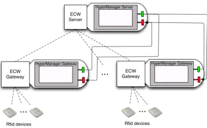
As an illustrative example, the internals of a GCM primitive component fea-turing three service methods — m1, m2 and m3 — and two client methods — m4 and m5 — are depicted by Figure 2.11. It illustrates both the global structure of the pNets represented by boxes, and the synchronization vectors represented by arrows — an ellipse is used when it involves more than one process.
Invocation on service methods — Q_mi, i∈{1,2,3} — go through a Queue, that
dis-patches the request — Serve_m* — to the Body. Serving the request consists in performing a Call_m* to the adequate service method, represented by the Mi
boxes in the figure. Once a result is computed, a synchronized R_m* action is emitted. This synchronization occurring between the service method and the Body stems from the fact that GCM primitive components are mono-threaded. Moreover, the careful reader will notice the fidi, i∈{1,2,3} in the figure. These are
the previously discussed futures (see Section 2.2), and act as promises for replies, leveraging asynchrony between components.
Service methods interact with external components by means of client inter-faces. This requires obtaining a proxy — GetProxy_m*, New_mi, i∈{4,5} — in order
2.3. PNETS: A FORMALISM FOR DEFINING BEHAVIOURAL SEMANTICS23
Primitive Component Example
M1 M3 !Recycle m5(p5) !Recycle m4(p4) GetValue m4(p4, val) Serve m*(f id⇤, arg) Queue PM m5 PM m4 Body ... Call m*(arg) !R m1(f id1, val) !R m2(f id2, val) !R m3(f id3, val) !R m*(f id⇤) !R *(val) ?Q m3(f id3, arg) ?Q m2(f id2, arg)
?Q m1(f id1, arg) ?R m5(p5, val)
?R m4(p4, val) !Q m5(p5, arg) !Q m4(p4, arg) GetValue m5(p5, val) New m5(p5) GetPro xy m* New m4(p4) Proxy m4[p4] Proxy m5[p5]
Figure 2.11: pNet representing a primitive component
— goes to the proxy used to call the external component. Then, a GetValue_-mi, i∈{4,5} is performed in order to access the result in the method being served.
Finally, Recycle_mi, i∈{4,5} actions can be performed in order to release the proxies.
The behaviour of the Queue and the Body elements should pose no doubt. The former acts as a queue with a FIFO policy, raising an exception if its capacity is exceeded. The latter dispatches the requests to the appropriate method and awaits its return, thus preventing the service of other requests in parallel.
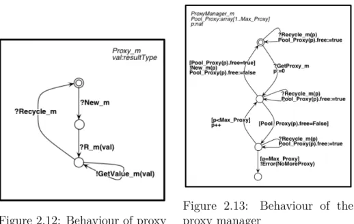
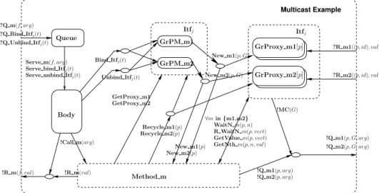
The handling of proxies however, is not as straightforward and deserves a closer look. Figures 2.12 and 2.13 illustrate the behaviour of the Proxies and Proxy Managers, respectively. Upon reception of a New_mi action, a Proxy waits for
the reply of the method invoked with it — R_m —, making thereafter its result available — GetValue_m. As soon as the reply is received, the Proxy can potentially be recycled through a Recycle_m action.
The behaviour of the Proxy Manager is slightly more elaborated. It maintains a pool of proxies, keeping track of those available and those already allocated. On the reception of a GetProxy_m action, it activates a new proxy — New_m — if there is one available. Should that not be the case, an Error(NoMoreProxy) action is emitted. As expected, a Recycle_m action frees a previously allocated proxy.
Figure 2.12: Behaviour of proxy Figure 2.13: Behaviour of theproxy manager
2.3.2 Coping with structural reconfigurations
As mentioned in Section 2.1, the GCM also contemplates non-functional aspects such as structural reconfigurations. This means that the architecture of the appli-cation can evolve at runtime (e.g. by establishing new bindings, removing existing ones, ...).
For GCM applications bind and unbind operations are handled by the com-ponent owning the client interface that is supposed to be reconfigurable. This should come as no surprise, indeed, it follows the same spirit as in object-oriented languages: an object holds the reference to a target object; it is this object that must change the reference it holds. Moreover, we recall that client interfaces can be of singleton or multicast cardinality. The former is bound to at most one server interface, while the latter needs to potentially handle several recipients. Therefore, their reconfiguration is dealt in different manners.
Let us first illustrate how a reconfigurable client singleton interface is modelled in pNets. A component is equipped with a binding controller interface to bind and unbind its client singleton interfaces. As depicted by Figure 2.14, the binding controller pLTS attached to each of them controls their bindings.
Indeed, we allow for reconfigurations by defining two new request messages for the binding and unbinding of interfaces. These are delegated to a binding controller
2.3. PNETS: A FORMALISM FOR DEFINING BEHAVIOURAL SEMANTICS25
Primitive with Binding Controller
M Queue !Q m(f, t, arg) [t=S1.Itf ] Q m(f, arg) [t=S2.Itf´] Q m(f, arg) Body !Q m(f, arg) !Bound(t) Error(”unbound”) BCItfj !Unbound !Bound(t) ?Unbind Call m*(...) !Unbound Bind Itfj(t) S2 S1 ?Q Bind Itfj(t) ?Q Unbind Itfj !Q m(f, arg) Serve * Unbind Itf
j
?Bind(t)
Figure 2.14: Binding controller
that upon method invocation over these reconfigurable interfaces will check if they are indeed bound, emitting an error if it is not the case. Moreover, the target of the invocation is decided by checking its passed reference. For this reason one must know statically what are the possible target interfaces that a reconfigurable interface can be bound too.
Reconfigurations involving multicast interfaces require keeping track of a set of recipients. Figure 2.15 depicts the pNet specificities concerning the handling of such interfaces. Multicast Example GrPM m1 GrPM m2 Method m GrProxy m1[p] New m1(p) New m2(p) !R m(f, val) GetProxy m1 GetProxy m2 ?R m1((p, id), val) ?R m2((p, id), val) !R m(val) ?Q Unbind Itfj(t) ?Q m(f, arg) ?Q Bind Itfj(t) Bind Itfj(t) Unbind Itfj(t) !Q m1(p, arg) !Q m2(p, arg) !Q m1(p, G, arg) !Q m2(p, G, arg) GrProxy m2[p] !MC(G) New m1(p, G) New m2(p, G) Recycle m2(p) Recycle m1(p) 8m in {m1,m2} WaitN m(p, n) R WaitN m(p, vect) GetNth m(p, n, val) GetValue m(p, vect) Serve unbind Itfj(t)
Serve bind Itfj(t) Serve m(f, arg)
Itfj Itfj
Body Queue
!Call m(arg)