HAL Id: hal-02051246
https://hal.archives-ouvertes.fr/hal-02051246
Submitted on 27 Feb 2019
HAL is a multi-disciplinary open access
archive for the deposit and dissemination of
sci-entific research documents, whether they are
pub-lished or not. The documents may come from
teaching and research institutions in France or
abroad, or from public or private research centers.
L’archive ouverte pluridisciplinaire HAL, est
destinée au dépôt et à la diffusion de documents
scientifiques de niveau recherche, publiés ou non,
émanant des établissements d’enseignement et de
recherche français ou étrangers, des laboratoires
publics ou privés.
High-temperature oxidation resistance of
chromium-based coatings deposited by DLI-MOCVD for
enhanced protection of the inner surface of long tubes
Alexandre Michau, Francis Maury, Frédéric Schuster, Fernando Lomello,
Jean-Christophe Brachet, Elodie Rouesne, Matthieu Le Saux, Raphaël
Boichot, Michel Pons
To cite this version:
Alexandre Michau, Francis Maury, Frédéric Schuster, Fernando Lomello, Jean-Christophe Brachet, et
al.. High-temperature oxidation resistance of chromium-based coatings deposited by DLI-MOCVD
for enhanced protection of the inner surface of long tubes. Surface and Coatings Technology, Elsevier,
2018, 349, pp.1048-1057. �10.1016/j.surfcoat.2018.05.088�. �hal-02051246�
OATAO is an open access repository that collects the work of Toulouse
researchers and makes it freely available over the web where possible
Any correspondence concerning this service should be sent
to the repository administrator:
tech-oatao@listes-diff.inp-toulouse.fr
This is an author’s version published in:
http://oatao.univ-toulouse.fr/21939
To cite this version:
Michau, Alexandre and Maury, Francis
and Schuster, Frédéric and Lomello,
Fernando and Brachet, Jean-Christophe and Rouesne, Elodie and Le Saux,
Matthieu and Boichot, Raphaël and Pons, Michel High-temperature oxidation
resistance of chromium-based coatings deposited by DLI-MOCVD for enhanced
protection of the inner surface of long tubes. (2018) Surface and Coatings
Technology, 349. 1048-1057. ISSN 0257-8972
High-temperature oxidation resistance of chromium-based coatings
deposited by DLI-MOCVD for enhanced protection of the inner surface of
long tubes
A. Michau
a,⁎, F. Maury
b, F. Schuster
c, F. Lomello
a, J.-C. Brachet
d, E. Rouesne
d, M. Le Saux
d,
R. Boichot
e, M. Pons
ea
Den–Service d'Etudes Analytiques et de Réactivité des Surfaces (SEARS), CEA, Université Paris-Saclay, 91191 Gif sur Yvette, France bCIRIMAT, CNRS/INPT/UPS, 4 allée E. Monso, 31030 Toulouse cedex 4, France
cCEA Cross-Cutting Program on Materials and Processes Skills, 91191 Gif-sur-Yvette, France d
Den–Service de Recherches Métallurgiques Appliquées (SRMA), CEA, Université Paris-Saclay, 91191 Gif sur Yvette, France eUniversity Grenoble Alpes, SIMAP, CNRS, 38000 Grenoble, France
A R T I C L E I N F O Keywords: DLI-MOCVD Protective coatings Cr-based coatings Oxidation resistance Corrosion study A B S T R A C T
For nuclear safety issues, there is an international effort to develop innovative “Enhanced Accident Tolerant Fuels” (EATF) materials. EATF cladding tubes are of particular interest because they constitute the first barrier against radioactive fission species dispersal in case of accidental scenario such as LOCA (LOss of Coolant Accident). Actual nuclear fuel claddings are made from Zr-based alloys and to increase safety margins, both mechanical strength and resistance to high-temperature oxidation have to be improved. Several alternatives using high-temperature oxidation resistant coatings for outer-wall protection have been proposed worldwide but there is currently no solution for the inner-wall protection. In order to resist to high temperature steam en-vironment upon LOCA transients, internal Cr-based coatings deposited by DLI-MOCVD (Direct Liquid Injection of MetalOrganic precursors) were investigated. These hard metallurgical coatings could also be used in high-temperature corrosive environments as those encountered in aeronautics and other industries to protect 3D complex components. Thanks to a suitable chemistry of the liquid Cr precursor, bis(ethylbenzene)chromium, different coatings were deposited including: metal Cr, chromium carbides CrxCyand mixed carbides CrxSizCy.
The high-temperature behavior of these Cr-based coatings under oxidizing atmospheres has been studied using several techniques and various oxidation tests including pure steam environment followed by water quenching down to room temperature to be representative of LOCA situations. Amorphous CrxCycoatings showed the most
promising properties. For instance compared to uncoated substrate, they shift the catastrophic oxidation towards higher temperatures and delay the complete oxidation of the substrate at 1473 K of > 2 h. The results are dis-cussed in terms of oxidation mechanisms and protection of the fuel claddings inner surface deduced from fine characterizations of the samples before and after oxidation tests.
1. Introduction
Fukushima-Daichii nuclear accident triggered a common interna-tional research effort to increase existing safety margins for both nominal and accidental conditions. Among these works, several aspects of nuclear power plants are reviewed worldwide, including the first safety barrier against dispersal of radioactive fission species. This function is ensured in pressurized water reactors by components called fuel cladding tubes, made of zirconium alloy, approximately 4 m long with an inner diameter and a thickness of about 8.4 mm and 0.6 mm
respectively. These long tubes, which contain the nuclear fuel, were mainly chosen due to their neutron transparency, in addition to their good corrosion resistance in pressurized water at ~573 K from the primary circuit and their good mechanical properties under irradiation. To increase the safety margins, in particular in hypothetical accidental conditions such as LOCA (LOss of Coolant Accident), both mechanical strength and resistance to oxidation at high temperature of the cladding have to be further improved. These new solutions are developed as Enhanced Accident Tolerant Fuels (EATF) [1].
Two solutions with different time scales are currently under
⁎Corresponding author.
E-mail address:alexandre.michau@cea.fr(A. Michau). https://doi.org/10.1016/j.surfcoat.2018.05.088
viscosity of BEBC, its dilution in toluene was required, both to inject and vaporize it efficiently but also to adjust its concentration in the gas phase. BEBC belongs to the metalorganic bis(arene)M family where M is a transition metal of columns V and VI. Other precursors from the bis (arene)Cr group were previously used to deposit Cr-based coatings by DLI-MOCVD [29]. It appeared that regardless the bis(arene)Cr pre-cursor when it is mixed with toluene, its thermal decomposition always gives chromium carbide coatings with the same atomic composition and microstructural features [31–33]. Depending on the deposition temperature, the structure of the coating is amorphous (≤773 K) or polycrystalline (> 773 K) [31–33]. It is also possible to inhibit the in-corporation of carbon into the coatings by adding a sulphur-containing (C6H5SH) or a chlorine-containing (C6Cl6) inhibitor into the precursor
solution, leading to the deposition of polycrystalline metal Cr coatings [24,32,34–36]. Finally, low amounts of silicon can be introduced in the amorphous chromium carbide coatings by incorporating diphe-nylsilane ((C6H5)2SiH2) to the precursor solution.
Amorphous chromium carbide a-CrxCycoatings were deposited on
flat substrates at 723 K and 6.7 ∗ 103Pa and directly inside cladding tube sections at 673 K and 6.7 ∗ 102Pa by injecting a solution of BEBC
and toluene at 3.0 ∗ 10−1mol·L−1.
Crystalline metallic Cr coatings were deposited at 673 K and 6.7 ∗ 103Pa by injecting a single solution of BEBC in toluene at
3.5 ∗ 10−1mol·L−1 with an addition of thiophenol C
6H5SH at
7.0 ∗ 10−3mol·L−1. To avoid the columnar growth obtained by this
process when a monolithic layer is deposited, a multilayer architecture has been developed. To do this, the growth of the layer was interrupted regularly for about 1 min by stopping the injection of the reactive vapor phase without stopping the reactor heating and the carrier gas flow rate, then it was injected again to start a new sequence without venting the reactor to ambient air. This causes a new nucleation and growth. This cycle was repeated 9 times for the samples studied here.
Mixed amorphous carbide CrxSizCycoatings were deposited at 773
and 723 K with a pressure of 6.7 ∗ 103Pa by injecting a single-solution
of BEBC in toluene at 3.0 ∗ 10−1mol·L−1 with an addition of
(C6H5)2SiH2at 4.5 ∗ 10−2mol·L−1(15 mol% compared to BEBC).
In all depositions, the carrier gas was nitrogen with a 500 sccm flow rate. The injection rate of the liquid solution was between 0.3 and 1.0 mL·min−1. The evaporation chamber was heated at 473 K and was
fed with N2preheated at 453 K as carrier gas.
Zircaloy-4 (namely Zr-4), stainless steel (SS304L) and silicon flat samples, or directly the inner-wall of Zr-4 tubes were used as substrates. The flat substrates were previously degreased for a few minutes in acetone and an ultrasound alcoholic bath, then dried under a N2stream
at room temperature and placed under vacuum on the sample-holder in the reactor before deposition. The 1 m long Zr-4 tube segments were cleaned with the alcoholic solution, dried with a N2stream and placed
under vacuum on the experimental set-up. The silicon substrates were Si(100) wafers passivated by a SixNylayer approximately 200 nm thick
acting as a barrier for the coating. The commercial composition of Zr-4 is given in [23].
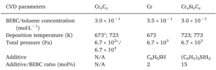
Table 1summarizes the main deposition conditions used for
DLI-Table 1
CVD parameters leading to the deposition of CrxCy, Cr and CrxSizCycoatings in
this work. CVD parameters CrxCy Cr CrxSizCy BEBC/toluene concentration (mol·L−1) 3.0 ∗ 10−1 3.5 ∗ 10−1 3.0 ∗ 10−1 Deposition temperature (K) 673a; 723 673 723; 773 Total pressure (Pa) 6.7 ∗ 102a/
6.7 ∗ 103
6.7 ∗ 103 6.7 ∗ 103 Additive N/A C6H5SH (C6H5)2SiH2 Additive/BEBC ratio (mol%) N/A 2 15
a
Specific conditions applied for the deposition inside Zr-4 cladding tubes.
investigation. The first solution is expected to be implemented at short or mid-term, implying that it would require only incremental techno-logical improvements compared to the current solution. The idea is to increase significantly and relatively quickly the existing safety margins.
The second solution is expected to be a greater challenge for safety margins, with a true technology breakthrough. However, concepts for this long-term solution are less mature. We can cite advanced and promising works on SiC-SiC composites [2–6], monolithic SiC tubes [7]
and free-standing Mo claddings [8] by CVD (Chemical Vapor
Deposi-tion).
All the short or mid-term solutions are generally based on zirconium alloy cladding tubes, enhanced by a special architecture with one or several other materials, usually an outer protective coating. A single layer of metallic chromium is one of the most investigated solutions. They are deposited by thermal spray [9–11], laser cladding [12] or PVD
(Physical Vapor Deposition) [13–16]. Other coating materials and
ar-chitectures are developed like non-metallic coatings, pure metals, in-termetallics, metallic alloys coatings, oxides, carbides including ternary carbides as MAX phases [17, 18], nitrides, composites and multilayers
[19].
All protective coatings on zirconium alloys are designed for outer-wall deposition on cladding tubes but there is currently no solution for the inner-wall protection [1]. In fact, upon LOCA transients, the fuel
cladding may experience ballooning and burst. Then, the cladding in-ternal surface can be exposed to steam environment at high tempera-ture, leading to fast inner oxidation and secondary hydriding, which induce significant additional embrittlement of the claddings [20–23].
In order to resist to this harsh environment, internal Cr-based coatings deposited by low pressure DLI-MOCVD (Direct Liquid Injection - MetalOrganic Chemical Vapor Deposition) have been investigated. DLI-MOCVD is indeed a suitable deposition process in order to homo-geneously coat the inside of long and narrow tubes with a high shape factor (> 500). Moreover, with an adequately chosen chemical system, consisting of a liquid solution of bis(arene)chromium as molecular precursor in a hydrocarbon solvent, deposition can be performed at sufficiently low temperatures, around 673 K [24], to avoid any
mod-ification of the metallurgical state of the zirconium alloy. DLI-MOCVD is currently studied in order to protect the inner surface of long clad-ding tube segments (~1 m). The process is being optimized to ensure a thickness uniformity of the coating along the tube through experi-mental studies coupled with numerical modeling of the reaction me-chanism and the whole deposition reactor [25].
These hard coatings could also be of use in high temperature cor-rosive environments such as those encountered in aeronautics, auto-motive [26] and some other industries [27] to protect components with
3D complex geometries. 2. Experimental details
2.1. Materials, deposition process and growth conditions
The deposition process took place in a horizontal hot-wall CVD re-actor. A liquid solution of precursor and solvent was injected in a commercial flash-vaporization chamber with the help of a Kemstream system (Direct Liquid Injection) [28]. Along with nitrogen as carrier
gas, the reactive vapor was transported to the reactor consisting either of a quartz tube (24 mm internal diameter) where flat substrates were placed on a stainless steel sample-holder for preliminary experiments or directly of a zirconium alloy tube (8.4 mm internal diameter). Both tubes were placed horizontally inside a 3-zone tubular resistive oven. Additional technical details on the DLI-MOCVD process can be found in [29, 30] and a sketch of a related set-up in [30] (the only difference in
this reference is that the reactor is vertical and not horizontal as in the present work).
Bis(ethylbenzene)chromium (namely BEBC) was used as liquid molecular precursor diluted in toluene. Because of the relatively high
MOCVD process.
2.2. Characterization methods and oxidation tests
The behavior of the coated Zr-4 samples in different oxidation tests was studied. In a first approach, mass change of coated and uncoated substrates was measured during thermal cycles using thermogravi-metric analyses (TGA; Setaram Sensys Evo) under different atmo-spheres. Samples (uncoated and coated on all faces) underwent a heating ramp from 298 to 1473 K at 40 K·min−1followed by an
iso-thermal annealing at 1473 K under dry and wet (27.5% of relative humidity measured at 298 K) air.
Three other oxidation tests, more representative of in-reactor acci-dental conditions, were performed on both flat samples (uncoated and coated on all faces) and cladding tube segments (uncoated and coated on their inner surface):
- Oxidation test #1: 1373 K for 14 min in static air followed by a 298 K water quench (flat samples);
- Oxidation test #2: two-sided oxidation at 1473 K for 10 min in pure (flowing) steam followed by a 298 K water quench (clad segment sample, CEA “DEZIROX-1” facility described in [37]);
- Oxidation test #3: two-sided oxidation 1473 K for 55 min in pure (flowing) steam followed by a 298 K water quench (clad segment sample, CEA “DEZIROX-1” facility);
The mass gain due to the oxidation was measured after the water quenching and drying of the sample. These last two tests performed under pure flowing steam are representative of LOCA scenario (Design-Based-Accident conditions) whereas TGA and oxidation test #1 were carried out under air.
Before and generally after oxidation tests, coating microstructures were observed by Scanning Electron Microscopy (SEM; Leo-435VP), Transmission Electron Microscopy (TEM; (JEOL JEM 2100 equipped with a 200 kV FEG), and Electron Back-Scattered Diffraction (EBSD) analyses (NordlysNano EBSD Detector with the AZtecHKL software installed on a SEM-FEG JEOL JSM-7100TTLS LV). Crystallographic structures of as-deposited coatings were investigated by X-ray Diffraction (XRD) using a Bruker D8-2 diffractometer equipped with a graphite monochromator (Bragg-Brentano configuration; Cu Kα radia-tion). Their evolution with temperature was studied during in situ High-Temperature (HT) XRD under Ar atmosphere. Chemical compositions of the coatings were measured by Electron Probe MicroAnalysis (EPMA; Cameca SXFive, 15 kV and 20 nA) and Glow Discharge Optical
Emission Spectroscopy (GDOES). Rutherford Backscattering
Spectrometry (RBS) was performed to estimate the density of CrxCy
coatings using a primary He+ ion beam of 2.8 MeV energy for the
thinnest films or H+ion beam of 1.5 MeV for the thickest coatings. Finally, chemical environments and bonds within deposited coatings were determined by X-ray Photoelectron Spectroscopy (XPS; Thermo Scientific K-Alpha, equipped with a monochromatic Al X-ray source). SEM and XRD analysis were systematically performed both on as-de-posited coatings and after oxidation tests of the samples. The nitride-passivated Si substrates were mainly used for SEM and XRD analyses and thickness measurements on cross-sections obtained by cleavage. 3. Results and discussion
3.1. Cr coatings
3.1.1. Microstructural and chemical composition analysis
When metallic Cr coatings are deposited by this low pressure DLI-MOCVD process as monolithic layers they exhibit a columnar micro-structure with inter-column spaces (porosities) open almost from the interface with the substrate to the outer surface, i.e. the external en-vironment and are visible on SEM micrographs [24]. As a result, this
microstructure is not at all favorable for an efficient diffusion barrier against oxidation at high temperature. A way to overcome this problem is to prevent columnar growth, which can be achieved by a multilayer architecture. Indeed, the columns begin to develop perpendicularly to the surface of the substrate only after a minimum thickness of a few hundred nanometers of a compact sublayer. Thus, by interrupting the growth near such critical thickness, a new nucleation step and growth is caused and the development of the columns is prevented.
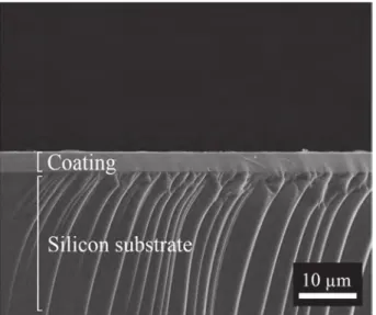
Polycrystalline metallic Cr coatings were deposited at 673 K with a multilayer architecture (Fig. 1). Thanks to this layered structuration, they exhibit a denser microstructure than columnar morphology ob-served for monolithic coatings. It was also obob-served by XRD and EBSD, as reported in [24], that they are mainly constituted of the stable bcc-Cr phase with a relatively low amount (< 6%) of the cubic metastable δ-Cr phase. These coatings undergo an irreversible transformation of the metastable Cr phase into the stable Cr phase by annealing in air at 723 K, and then they form chromium oxides above 823 K. The average atomic composition of as-deposited coatings measured by EPMA is Cr0.92C0.04O0,03S0.01. Apart from chromium, they contain a residual
amount of carbon and a slight contamination by oxygen and sulphur. Carbon comes from the metalorganic precursor BEBC and traces of sulphur come from thiophenol used as a carbon inhibitor. Indeed, carbon incorporation was prevented by a surface site competition be-tween BEBC derivatives and thiophenol molecules. However, there is likely a small amount of thiophenol that decomposes and incorporates traces of sulphur. The low carbon content indicates that the efficiency of the S-containing inhibitor is not perfect and that C also originates from other side reactions. More details on the chemical and structural characteristics of these metal Cr coatings are reported in [24]. 3.1.2. Oxidation study
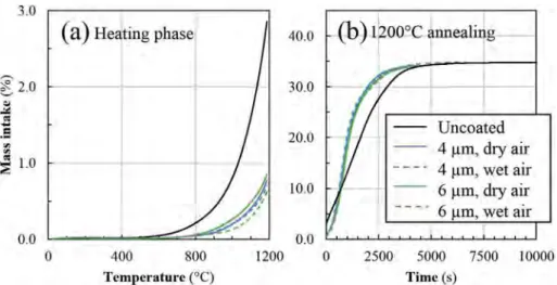
Mass gains of uncoated, 4 μm Cr coated and 6 μm Cr coated Zircaloy-4 samples measured by TGA during heating ramp and iso-thermal annealing under dry and wet air at 1473 K are presented in
Fig. 2. During the heating ramp, as shown inFig. 2(a), the oxidation kinetics of coated samples is slowed down by the presence of the pro-tective Cr layer. At the end of the heating phase, the mass uptake of coated substrates is comprised between 0.60 and 0.85% (1.6 to 2.2 mg·cm−2) while it reaches 2.85% (7.5 mg·cm−2) for the uncoated
Zircaloy-4 samples under both dry and wet air. There is no effect of the coating thickness either. However, at 1473 K (Fig. 2(b)), the oxidation of coated samples immediately catches up that of uncoated Zircaloy-4 to reach approximately 35% (92 mg·cm−2) without providing any delay
compared to bare Zr-4 substrate. All samples oxidize at the same rate in
Fig. 1. Multilayer metal Cr coating deposited by DLI-MOCVD on Si substrate at 673 K from BEBC precursor with addition of thiophenol as inhibitor of carbon incorporation. The architecture of the coating consists in 9 layers in order to reduce the average grain size and to improve its density.
dry or wet air. By neglecting the Cr layer compared to the thickness of the Zircaloy substrate, this mass gain threshold of about 35% is in good agreement with the total transformation of Zr into ZrO2(calculated
36%) confirming the complete oxidation of the Zr alloy.
After 14 min at 1373 K in static air followed by a 298 K water quench (test #1), a 2.2 mg·cm−2mass intake was measured for both
2 μm and 4 μm Cr coated samples. It appears on SEM observations and GDOES profiles that the Cr coating is partially oxidized as shown in
Fig. 3. Despite the crystallization of the coating due to high temperature leading to the growth of grains and the disappearance of the multilayer architecture, the coating still acts as a sacrificial protection barrier against Zircaloy-4 oxidation. Several layers can be identified from
Fig. 3. First of all, a fully oxidized layer is observed at the external surface (~1.5 μm), followed by a partially oxidized chromium layer constituted of Cr, O and C (~3 μm). Then, a diffusion area (~2 μm) not visible on SEM picture appears on GDOES profile between the coating and the non-oxidized substrate. XRD analyses did not reveal the pre-sence of any crystallized phase at the interface produced by the inter-diffusion between elements such as ZrC or intermetallic phases like ZrCr2.
The multilayer architecture of Cr coatings developed to improve
their density and their polycrystalline structure produces an equiaxial-like microstructure with many small grains with an average grain size approximately equal to the period of the multilayer, i.e. the thickness of the individual sublayers. Subsequently, grain boundaries are essential perpendicular to the interfaces created by the multilayer growth mode as demonstrated by EBSD analyses in theFig. 6of [24]. This micro-structure is not sufficiently optimized and finally grants unsatisfying protection to Zircaloy-4 substrate over 1373 K. Despite the absence of open porosity or grain boundaries induced by a columnar growth di-rectly perpendicular to the surface of the substrate, both the multi-plication of interfaces parallel to the substrate and the network of grain boundaries connecting the different sublayers are preferential ways for rapid diffusion of oxygen to the Zr-4 substrate. As a result these DLI-MOCVD Cr coatings exhibit poor performances in our oxidation con-ditions compared to other Cr-based coatings.
3.2. CrxCycoatings
3.2.1. Microstructural and chemical composition analysis
Amorphous chromium carbide coatings as-deposited by DLI-MOCVD at temperatures lower than 773 K are very dense as deduced from the absence of porosities visible by SEM and TEM analyses [31]. This is supported by RBS analyses. Indeed from the atomic composition determined by EPMA and the thickness of the coatings measured by SEM, the density of two amorphous a-CrxCycoatings deposited at 723 K
and 773 K was estimated by RBS equal to 5.4 ± 0.7 g·cm−3 and
6.6 ± 0.6 g·cm−3, which is very close to 6.7 g·cm−3for bulk Cr 3C2.
Interestingly for barrier coatings, they have a glassy-like microstructure without any grains and grain boundary visible by SEM (Fig. 4) and TEM images recently reported in [31]. As-deposited coatings show only broad humps on their XRD patterns at room temperature (Fig. 5) with no evidence of diffraction peaks from polycrystalline phases [31]. During in situ HT-XRD (Fig. 5) under Ar atmosphere, it was observed that coatings crystallize partially into Cr7C3at 853 K, then Cr3C2
ap-pears at 873 K followed by Cr2O3around 883 K due to traces of oxygen.
It is interesting to note that the average atomic composition measured by EPMA is Cr0.64C0.33O0.03which corresponds to a stoichiometry
be-tween Cr7C3and Cr3C2. More details on the microstructure of this
a-CrxCycoating are reported in a recent paper [31].
3.2.2. Oxidation study
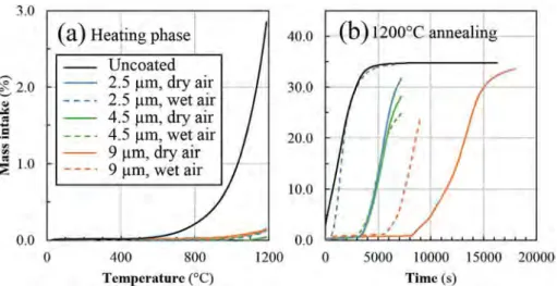
Three different thicknesses of CrxCy coatings were tested during
TGA, 2.5 μm, 4.5 μm and 9 μm, and the results were compared to the uncoated Zr-4 substrate. When exposed to dry or wet air, coated sam-ples show at the end of the heating phase up to 1473 K a mass gain
Fig. 2. TGA of uncoated, 4 μm Cr coated and 6 μm Cr coated Zircaloy-4 substrates under dry and wet air, during (a) the heating ramp from room temperature to 1473 K and (b) the isothermal annealing at 1473 K.
Fig. 3. GDOES composition profile of a 4 μm Cr coated Zircaloy-4 substrate after oxidation test #1 superimposed to the corresponding back-scattered electrons (BSE) SEM cross-section.
always lower than 0.15% (0.4 mg·cm−2), compared to 2.85%
(7.5 mg·cm−2) for uncoated Zr-4 substrate. There is no strong
differ-ence between coated samples regarding the infludiffer-ence of the coating thickness or the atmosphere in the temperature rise phase as shown in
Fig. 6(a).
Unlike Cr coated and uncoated Zircaloy-4 substrates, mass uptakes of CrxCycoated samples during the 1473 K annealing clearly show a
delay to their complete oxidation, as illustrated inFig. 6(b). It appears that this delay increases with increasing the coating thickness and is higher for dry air than for wet air, to reach a remarkable value > 2 h. SEM observations of oxidized samples show that the presence of the coating is beneficial to their mechanical integrity, acting as a barrier enclosing Zircaloy-4. As it was recently observed for bulk Cr7C3, the
oxidized surface of our coatings consists only of Cr2O3and does not
show any sign of peeling [38]. On the contrary, uncoated Zircaloy-4 samples are strongly deteriorated by oxidation and loss some parts.
Oxidation kinetics of amorphous CrxCycoatings is almost 5 times
slower than that of Cr coating with mass gains ranging from 0.3 to 0.5 mg·cm−2 (compared to 2.2 mg·cm−2) after oxidation test #1
(1373 K for 14 min in static air followed by a 298 K water quench) for 2.5 μm, 4.5 μm and 9 μm CrxCycoated Zr-4 samples. Despite their
re-latively low values, mass gains are increasing with the thickness of
coatings. As the oxidation test was similar for all samples, the oxygen content available in the oxidative atmosphere did not limit the oxida-tion kinetics, which was essentially controlled by the total amount of Cr and C, the coating playing a sacrificial role in the oxidation mechanism. Despite their high-temperature oxidation and the presence of rare local cracks, the coatings are still adherent to the Zircaloy-4 substrate. CrxCycoatings constitute an efficient protection for Zircaloy-4 thanks to
their excellent conformity and their microstructure, which remains very dense (Fig. 7) even after the oxidation test and the water quench. In-deed, their crystallization does not lead to a noticeable grain growth or to the appearance of grain boundaries, which would have been dis-advantageous for oxidation resistance since they are preferential paths for diffusion. The underlying Zircaloy-4 is not oxidized except very locally below some cracks in the coating, as the GDOES profile inFig. 7
does not show any additional oxygen in the Zr matrix.
Based onFig. 7, the oxidized microstructure of the coating can be represented as a superposition of several layers: a surface layer of chromia Cr2O3 (~1.5 μm) in direct contact with the oxidative
atmo-sphere, the partially oxidized coating containing Cr, C and O (~2.5 μm) and the non-oxidized coating (~2.0 μm). An inter-diffusion sublayer of approximately 10 μm is present between Cr and C from the coating and Zr from the substrate. XRD analyses revealed the presence of Cr3C2in
the coating after its crystallization due to the sustained thermal treat-ment, and traces of the ZrC phase, as a result of Cr, C and Zr inter-diffusion.
Since amorphous chromium carbide coatings gave promising results under air oxidation, two-sided oxidation tests have then been per-formed in flowing steam for 600 s (test #2) and 3300 s (test #3) at 1473 K on uncoated and CrxCyinner-coated clad segments. The
con-ditions are more representative of LOCA. These samples were finally quenched in water at room temperature. They consist in 3 cm-long sections cut from a 1 m-long clad segment with amorphous CrxCy
de-posited on its inner surface. The coating thickness varied along the 1 m-long segment, which allowed testing for several coating thicknesses.
Table 2 summarizes the oxidation conditions and the associated mass gain (per unit surface area) values measured.
Taking into account the cladding thickness, the holding for 600 s at 1473 K corresponds to an Equivalent Cladding Reacted (ECR, (*)) value close to 17% for one sided-steam oxidation (and ~34% for two-sided oxidation) according to the “Baker-Just” oxidation rate correlation for an uncoated Zircaloy-4 based cladding [39]. An ECR value of 17% corresponds to the “historical” LOCA regulation limit to ensure sig-nificant residual post-quenching clad ductility [40]. The ECR parameter represents the fraction of the metallic clad wall thickness that has been
Fig. 4. Amorphous CrxCycoating deposited by DLI-MOCVD on a Si substrate at
723 K from BEBC precursor.
transformed into oxide assuming that all the oxygen which has reacted with the clad has been transformed into stoichiometric zirconia.
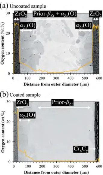
Figs. 8 and 9show the post-quenching microstructures and the as-sociated oxygen diffusion profiles of reference uncoated and CrxCy
inner-coated samples, after steam oxidation for 600 s at 1473 K. It is obvious from these results that, for these steam oxidation conditions, the internal CrxCycoating has protected the inner clad surface from
significant oxidation while, for the uncoated reference materials, 70–100 μm-thick brittle zirconia and oxygen stabilized αZr(O) layers
have formed at both outer and inner surfaces. Such results are con-sistent with the mass gain values measured for uncoated reference Zircaloy-4 being approximately twice the value obtained for the CrxCy
Fig. 6. TGA of uncoated, 2.5 μm CrxCycoated, 4.5 μm CrxCycoated and 9 μm CrxCycoated Zircaloy-4 substrates under dry (solid curves) and wet air (dotted curves),
during (a) the heating ramp from room temperature to 1473 K and (b) the 1473 K thermal annealing.
Fig. 7. GDOES composition profile of a 4.5 μm CrxCycoated Zircaloy-4
sub-strate after oxidation test #1 superimposed to an associated SEM cross-section.
Table 2
Two-sided steam oxidation conditions applied before final water quenching and mass gain values measured post-mortem (tests #2 and #3).
Material Steam oxidation temperature (K) Steam oxidation time (s) Mass gain (mg·cm−2)
Uncoated ref. Zircaloy-4 1473 600 14.9 ± 0.1
CrxCyinner-coated (~20 μm) Zircaloy-4 8.3 ± 0.1
Uncoated ref. Zircaloy-4 3330 34.6 ± 0.1
CrxCyinner-coated (~25 μm) Zircaloy-4 29.2 ± 0.1
Fig. 8. Optical polarized micrographs cross-sections after oxidation test #2 of (a) an uncoated reference Zircaloy-4 clad segment and (b) a CrxCyinner-coated
Zircaloy-4 clad segment (Out. and Int. respectively stand for outer and inner side).
inner-coated sample. Moreover, it can be observed from EPMA results that the average oxygen content of the inner prior-βZrlayer (αZrphase
with a typical Widmanstätten or parallel-lath structure morphology resulting from the transformation of βZrduring cooling) is higher in the
uncoated reference Zircaloy-4 than in the inner-coated sample, and close to the oxygen solubility in the βZrphase at 1473 K [41]. Such an
oxygen concentration value in the prior-βZrlayer is known to induce a
brittle failure mode at room temperature [42–44]. Since the inner prior-βZrlayer is known to ensure most of the post-quenching residual
duc-tility and toughness of Zr-based cladding oxidized at high temperature [42,43], the results confirm the beneficial influence of the inner CrxCy
coating by protecting the inner clad surface from early oxygen diffu-sion.
On cross-sections, it seems a partial detachment of the coating happens in certain place but we think this mainly occurs during the preparation of the sample to obtain the transverse cuts as inFig. 9. We have not identified at this stage any adhesion problem on Zr-4. Also, on cross-section micrographs as inFig. 9, cracks are sometimes observed crossing completely the coatings up to the interface with the substrate. Probably most of them originate from the preparation of the sample but it is quite likely that some of these cracks appeared on as-deposited coatings and could be induced for instance by thermal stresses. Indeed, one of these cracks that traversed perpendicularly all the coating ap-pears inFig. 9(b) on the inner-surface of the cladding. It has been in-filtrated by oxygen during the oxidation test and consequently it was entirely coated by chromium oxide up to the Zr-4 substrate, which begins to be locally oxidized, as revealed by the dark contrast deli-neating the diffusion zone of oxygen in Zr-4 from the bottom of the crack.
Fig. 10gives more insights into the microstructural evolution of the inner-coated clad segment upon high-temperature steam oxidation. From the detailed SEM-EBSD analysis presented inFig. 10(c), it can be observed that the outer periphery is composed of nearly 100% of chromium oxide Cr2O3with submicronic grains, while the rest of the
coating displays a complex mixture of partially crystallized carbides (Cr3C2and Cr7C3) and submicronic Cr2O3oxide grains. It can also be
assumed that the non-indexed zones (in dark grey inFig. 10(b) and (c)) correspond to residual amorphous CrxCycarbides and/or to nanometric
grains which could not be identified by SEM-EBSD due to the instru-mental spatial resolution. Additionally, due to some carbon diffusion (also detected from XRD and EPMA measurements) into the underlying Zircaloy-4 substrate, a more or less continuous ZrC layer formed at the Zr/CrxCyinterface. Finally, some porosities can be observed at the
vi-cinity of the crystallized carbides which may be due to the local volume changes associated with the crystallization process (i.e. crystalline carbides formation from the initial amorphous state). One can make also the assumption that the coarser porosities lying near the ZrC/CrxCy
interface have been induced by some local “Kirkendall” effects [45], because of the strongly different diffusivities of the chemical species (C, Cr, Zr) involved into the high-temperature inter-diffusion process be-tween the outer CrC scale and the Zircaloy-4 substrate. However, no
Fig. 9. Superposition of SEM micrographs (BSE mode) and EPMA oxygen profiles corresponding to the clad wall thickness after oxidation test #2 of (a) an uncoated reference Zircaloy-4 clad segment and (b) a CrxCyinner-coated
Zircaloy-4 clad segment.
Fig. 10. Inner surface of a CrxCycoated clad section after oxidation test #2, (a) SEM observation with BSE, (b) SEM-EBSD quality map and (c) SEM-EBSD map in
significant macroscopic delamination of the partially oxidized CrxCy
inner coating occurred. This indicates that this type of coating has some capacity to survive under the high-temperature steam oxidation and subsequent water quenching typical of hypothetical LOCA events.
An additional high-temperature steam oxidation test has been per-formed for nearly 1 h (3330 s) at 1474 K (test #3).Fig. 11shows the resultant microstructures for both 3 cm long uncoated (a) and CrxCy
inner-coated (b) clad sections. Consistently with the mass gain values measured (Table 2), it is obvious from these examinations that for this much longer steam oxidation at 1473 K, the inner coating has almost disappeared and thus was no more protective against high temperature steam oxidation. Part of the Cr originating from the coating was con-sumed by diffusion in the substrate, as revealed by the EPMA profiles of cross-sections of Fig. 11 (not shown for clarity), and another part formed chromium oxide, which was peeled off and is not visible in the area ofFig. 11.
However, in hypothetical LOCA situations, oxidation of the cladding inner surface may occur after clad burst occurrence as a result of steam ingress through the burst opening into the gap between the nuclear fuel pellet and the inner clad surface. In such situation, one of the main issues is related to very localized secondary hydriding phenomena (a few centimeters apart from the burst opening) due to steam starvation conditions. It has been observed that in these conditions, secondary hydriding is a very fast process inducing local hydrogen concentration peaks up to thousands of weight-ppm after only a few minutes at 1373–1473 K [20–23]. Such a high hydrogen content may induce a strong local embrittlement of the cladding. Then, it is believed that the inner coating studied here has a high potential to delay efficiently the occurrence of this embrittlement. Some high-temperature additional
oxidation tests are thus on-going to better address this issue. 3.3. CrxSizCycoatings
3.3.1. Microstructural and chemical composition analysis
Silicon is a relatively small element that has a great affinity for many elements and tends to form chemical bonds with a strong cova-lent character. As a result, it can form many compounds, including ternary carbides. When it is integrated into a structure at low tem-perature, silicon has the particularity of amorphizing it until a critical composition corresponding to a specific compound of the phase dia-gram can then crystallizes. In other words, doping with Si increases the crystallization temperature of amorphous carbides. Doping CrxCywith
Si was purposely realized in order to increase the crystallization tem-perature of the amorphous chromium carbide coatings during inten-tional or uninteninten-tional thermal treatments, providing more time before the appearance of grains boundaries that would favor oxygen diffusion. It is possible to incorporate small quantities of Si into amorphous chromium carbide coatings before forming crystallized silicides or mixed carbides by adding to the injected solution of BEBC an adequate Si-containing precursor, diphenysilane. Decomposition of the two pre-cursors leads to the growth of mixed amorphous chromium carbide CrxSizCy at low temperatures (723 and 773 K). Comparatively to
a-CrxCycoatings, CrxSizCycoatings exhibit also a dense and glassy-like
microstructure with no visible grains. It is worth noticing that BEBC catalyzes the decomposition of diphenylsilane in the CVD reactor. Indeed, injection of only diphenylsilane in solution with toluene did not allow the growth of Si or SiC coatings in our deposition conditions. CrxSizCycoatings deposited by DLI-MOCVD using a one-pot solution
with both precursors in toluene have an average composition of Cr0.66Si0.02C0.29O0.03.
As-deposited CrxSizCycoatings are amorphous and, as expected, in
situ HT-XRD analyses under Ar atmosphere have shown that they start to crystallize only from 1023 K, i.e. > 150 K above a-CrxCy(~853 K).
The phases Cr7C3and CrSi2are simultaneously appearing at 1023 K.
Coatings start oxidizing at 1123 K due to traces of oxygen and then partially crystallize into Cr3C2at 1273 K.
3.3.2. Oxidation study
When submitted to TGA (Fig. 12) under dry or wet air, like other Cr-based coatings, CrxSizCycoatings present a smaller mass uptake than
uncoated Zircaloy-4 samples, around 0.30% (0.8 mg·cm−2) for a 4 μm
thick coating, compared to 2.85% (7.5 mg·cm−2) without coating.
However, like metallic Cr coatings, they do not delay the complete oxidation of Zircaloy-4 substrates. Their behavior can be ranked in terms of protection efficiency between polycrystalline metallic Cr and amorphous CrxCy. It is believed that the low Si amount incorporated
(around 2 at.%) is not sufficient to form a continuous protective film as SiO2or mixed oxides, which should improve the barrier against
oxi-dation.
4. Conclusions and perspectives
All tested Cr-based coatings deposited by DLI-MOCVD based on the thermal decomposition of BEBC precursor increase the oxidation re-sistance of Zircaloy-4 under dry air, wet air or pure steam. The tem-perature required to trigger catastrophic oxidation of coated Zircaloy-4 is always pushed back towards higher values. Amorphous chromium carbide coatings are the most efficient because of their ability to delay complete oxidation of the substrate. They behave like an inner sacrifi-cial protection barrier for the Zircaloy-4 substrate against high-tem-perature oxidation (1473 K), even under pure steam and after water quenching.
Improved microstructure of metallic Cr coating with a multilayer architecture aiming at increasing its density and its polycrystalline structure finally turn out to be disadvantageous. By multiplying
Fig. 11. Optical polarized micrographs cross-sections after oxidation test #3 of (a) an uncoated reference Zircaloy-4 clad segment and (b) a CrxCyinner-coated
Zircaloy-4 clad segment (Out. and Int. respectively stand for outer and inner side).
interfaces between layers and perpendicular grain boundaries between the sublayers, the oxidation kinetics is accelerated compared to that of the very dense and glassy-like CrxCycoatings. Si-doping of CrxCyis also
ineffective regarding oxidation despite the higher crystallization tem-perature of the coatings under inert atmosphere but probably the in-fluence of the coating composition (not explored here) is a way of improvement.
The successful deposition by DLI-MOCVD of amorphous CrxCy
coatings on the inner-wall of 1 m-long cladding segments allowed the realization of various oxidation tests closer to the LOCA conditions. They demonstrate that this coating is a good candidate for an efficient inner protection of Zr-4 fuel cladding. They also prove that the DLI-MOCVD process is the first studied viable solution to protect the inside of nuclear fuel cladding as recently noticed in a review on this field [1]. As perspectives to this work, we will maintain our efforts to conduct new oxidation tests and continue the qualification of amorphous chromium carbide coatings on Zr-based claddings for EATFs. Hydrogen is another subject of study, in order to determine the capability of CrxCy
coatings to prevent from hydrogen diffusion, and thus from the clad-ding embrittlement due to the hydriclad-ding of the Zr-based substrates. Moreover, the behavior of coated claddings under irradiation will be investigated. Finally, upscaling of the process assisted by numerical modeling is already in progress, first by demonstrating the possibility to coat a bundle of 1 m-long clad segments, then by accessing to a full-length fuel cladding with homogeneous coverage.
References
[1] K.A. Terrani, Accident tolerant fuel cladding development: promise, status, and challenges, J. Nucl. Mater. 501 (2018) 13–30,http://dx.doi.org/10.1016/j. jnucmat.2017.12.043.
[2] N. Nakazato, H. Kishimoto, Y. Kohno, A. Kohyama, SiC/SiC fuel cladding by Nite process for innovative LWR-cladding forming process development, Ceramics for Environmental and Energy Applications II, John Wiley & Sons, Inc., 2014, pp. 109–115, ,http://dx.doi.org/10.1002/9781118771327.ch12.
[3] C.P. Deck, G.M. Jacobsen, J. Sheeder, O. Gutierrez, J. Zhang, J. Stone, H.E. Khalifa, C.A. Back, Characterization of SiC–SiC composites for accident tolerant fuel clad-ding, J. Nucl. Mater. 466 (2015) 667–681,http://dx.doi.org/10.1016/j.jnucmat. 2015.08.020.
[4] D. Kim, H.-G. Lee, J.Y. Park, W.-J. Kim, Fabrication and measurement of hoop strength of SiC triplex tube for nuclear fuel cladding applications, J. Nucl. Mater. 458 (2015) 29–36,http://dx.doi.org/10.1016/j.jnucmat.2014.11.117. [5] J. Braun, C. Guéneau, T. Alpettaz, C. Sauder, E. Brackx, R. Domenger, S. Gossé,
F. Balbaud-Célérier, Chemical compatibility between UO2fuel and SiC cladding for LWRs. Application to ATF (Accident-Tolerant Fuels), J. Nucl. Mater. 487 (2017) 380–395,http://dx.doi.org/10.1016/j.jnucmat.2017.02.031.
[6] K. Shapovalov, G.M. Jacobsen, L. Alva, N. Truesdale, C.P. Deck, X. Huang, Strength of SiCf-SiCmcomposite tube under uniaxial and multiaxial loading, J. Nucl. Mater. 500 (2018) 280–294,http://dx.doi.org/10.1016/j.jnucmat.2018.01.001. [7] P. Drieux, G. Chollon, S. Jacques, A. Allemand, D. Cavagnat, T. Buffeteau,
Experimental study of the chemical vapor deposition from CH3SiHCl2/H2: appli-cation to the synthesis of monolithic SiC tubes, Surf. Coat. Technol. 230 (2013) 137–144,http://dx.doi.org/10.1016/j.surfcoat.2013.06.046.
[8] M.F. Beaux, D.R. Vodnik, R.J. Peterson, B.L. Bennett, J.J. Salazar, T.G. Holesinger, G. King, S.A. Maloy, D.J. Devlin, I.O. Usov, Chemical vapor deposition of Mo tubes for fuel cladding applications, Surf. Coat. Technol. 337 (2018) 510–515,http://dx. doi.org/10.1016/j.surfcoat.2018.01.063.
[9] D.J. Park, H.G. Kim, Y.I. Jung, J.H. Park, J.H. Yang, Y.H. Koo, Behavior of an im-proved Zr fuel cladding with oxidation resistant coating under loss-of-coolant ac-cident conditions, J. Nucl. Mater. 482 (2016) 75–82,http://dx.doi.org/10.1016/j. jnucmat.2016.10.021.
[10] M. Ševeček, A. Gurgen, A. Seshadri, Y. Che, M. Wagih, B. Phillips, V. Champagne, K. Shirvan, Development of Cr cold spray–coated fuel cladding with enhanced ac-cident tolerance, Nucl. Eng. Technol. (2018),http://dx.doi.org/10.1016/j.net. 2017.12.011.
[11] B. Maier, H. Yeom, G. Johnson, T. Dabney, J. Walters, J. Romero, H. Shah, P. Xu, K. Sridharan, Development of cold spray coatings for accident-tolerant fuel cladding in light water reactors, JOM 70 (2018) 198–202,http://dx.doi.org/10.1007/ s11837-017-2643-9.
[12] H.-G. Kim, I.-H. Kim, Y.-I. Jung, D.-J. Park, J.-Y. Park, Y.-H. Koo, Adhesion property and high-temperature oxidation behavior of Cr-coated Zircaloy-4 cladding tube prepared by 3D laser coating, J. Nucl. Mater. 465 (2015) 531–539,http://dx.doi. org/10.1016/j.jnucmat.2015.06.030.
[13]I. Idarraga-Trujillo, M. Le Flem, J.-C. Brachet, M. Le Saux, D. Hamon, S. Muller, V. Vandenberghe, M. Tupin, E. Papin, E. Monsifrot, A. Billard, F. Schuster, Assessment at CEA of coated nuclear fuel cladding for LWRs with increasing mar-gins in LOCA and beyond LOCA conditions, Proceedings of TopFuel, 2013, pp. 860–867.
[14] J.-H. Park, H.-G. Kim, J. Park, Y.-I. Jung, D.-J. Park, Y.-H. Koo, High temperature steam-oxidation behavior of arc ion plated Cr coatings for accident tolerant fuel claddings, Surf. Coat. Technol. 280 (2015) 256–259,http://dx.doi.org/10.1016/j. surfcoat.2015.09.022.
[15] J. Bischoff, C. Delafoy, C. Vauglin, P. Barberis, C. Roubeyrie, D. Perche, D. Duthoo, F. Schuster, J.-C. Brachet, E.W. Schweitzer, K. Nimishakavi, AREVA NP's enhanced accident-tolerant fuel developments: focus on Cr-coated M5 cladding, Nucl. Eng. Technol. (2018),http://dx.doi.org/10.1016/j.net.2017.12.004.
[16]J.-C. Brachet, M. Dumerval, V. Lezaud-Chaillioux, M. Le Saux, E. Rouesne, D. Hamon, S. Urvoy, T. Guilbert, Q. Houmaire, C. Cobac, G. Nony, J. Rousselot, F. Lomello, F. Schuster, H. Palancher, J. Bischoff, E. Pouillier, Behavior of chro-mium coated M5(TM) claddings under LOCA conditions fuel, Proceedings of Water Reactor Fuel Performance Meeting, 2017.
[17]C. Tang, M. Stüber, M. Steinbrück, M. Grosse, S. Ulrich, H.J. Seifert, Assessment of high-temperature steam oxidation behavior of Zircaloy-4 with Ti2AlC coating de-posited by magnetron sputtering, Proceeding of the Nuclear Materials Conference, Montpellier, France, 2016.
[18]C. Tang, M. Steinbrück, M. Grosse, S. Ulrich, M. Stüber, H.J. Seifert, Evaluation of magnetron sputtered protective Zr-C-Al coatings for accident tolerant Zircaloy claddings, Proceedings of Water Reactor Fuel Performance Meeting, 2017. [19] C. Tang, M. Stüber, H.J. Seifert, M. Steinbrück, Protective coatings on
zirconium-based alloys as accident-tolerant fuel (ATF) claddings, Corros. Rev. 35 (2017) 141, , http://dx.doi.org/10.1515/corrrev-2017-0010.
[20] J.-C. Brachet, D. Hamon, M. Le Saux, V. Vandenberghe, C. Toffolon-Masclet, E. Rouesne, S. Urvoy, J.-L. Béchade, C. Raepsaet, J.-L. Lacour, G. Bayon, F. Ott, Study of secondary hydriding at high temperature in zirconium based nuclear fuel cladding tubes by coupling information from neutron radiography/tomography, electron probe micro analysis, micro elastic recoil detection analysis and laser in-duced breakdown spectroscopy microprobe, J. Nucl. Mater. 488 (2017) 267–286, http://dx.doi.org/10.1016/j.jnucmat.2017.03.009.
[21]M. Billone, Y. Yan, T. Burtseva, R. Daum, Cladding Embrittlement During
Fig. 12. TGA of uncoated and 4 μm CrxSizCycoated Zircaloy-4 substrates under dry and wet air, during (a) the heating ramp from room temperature to 1473 K and
Postulated Loss-of-coolant Accidents (NUREG/CR-6967), (2008). [22] F. Nagase, T. Fuketa, Effect of pre-hydriding on thermal shock resistance of
Zircaloy-4 cladding under simulated loss-of-coolant accident conditions, J. Nucl. Sci. Technol. 41 (2004) 723–730,http://dx.doi.org/10.1080/18811248.2004. 9715539.
[23] M. Grosse, J. Stuckert, M. Steinbrück, A. Kaestner, Secondary hydriding during LOCA – results from the QUENCH-L0 test, J. Nucl. Mater. 420 (2012) 575–582, http://dx.doi.org/10.1016/j.jnucmat.2011.11.045.
[24] A. Michau, F. Maury, F. Schuster, R. Boichot, M. Pons, Evidence for a Cr metastable phase as a tracer in DLI-MOCVD chromium hard coatings usable in high tempera-ture environment, Appl. Surf. Sci. 422 (2017) 198–206,http://dx.doi.org/10.1016/ j.apsusc.2017.05.253.
[25] A. Michau, F. Maury, F. Schuster, F. Lomello, R. Boichot, M. Pons, J.-C. Brachet, E. Monsifrot, Inner-side coatings for advanced fuel claddings processed by DLI-MOCVD, Proceedings of Water Reactor Fuel Performance Meeting, 2017. [26] M. Drozdz, K. Kyzio, Z. Grzesik, Chromium-based oxidation-resistant coatings for
the protection of engine valves in automotive vehicles, Mater. Technol. 51 (2017) 603–607,http://dx.doi.org/10.17222/mit.2016.151.
[27] F. Cai, X. Huang, Q. Yang, Mechanical properties, sliding wear and solid particle erosion behaviors of plasma enhanced magnetron sputtering CrSiCN coating sys-tems, Wear 324–325 (2015) 27–35,http://dx.doi.org/10.1016/j.wear.2014.11. 008.
[28] H. Guillon, G. Bonnafous, Vaporization of solid or liquid organic, organometallic or inorganic compounds, Gases and Instrumentation, May/June 2008, pp. 17–19. [29] F. Maury, A. Douard, S. Delclos, D. Samelor, C. Tendero, Multilayer chromium based coatings grown by atmospheric pressure direct liquid injection CVD, Surf. Coat. Technol. 204 (2009) 983–987,http://dx.doi.org/10.1016/j.surfcoat.2009.04. 020.
[30] A. Douard, F. Maury, Nanocrystalline chromium-based coatings deposited by DLI-MOCVD under atmospheric pressure from Cr(CO)6, Surf. Coat. Technol. 200 (2006) 6267–6271,http://dx.doi.org/10.1016/j.surfcoat.2005.11.043.
[31] A. Michau, F. Maury, F. Schuster, R. Boichot, M. Pons, E. Monsifrot, Chromium carbide growth at low temperature by a highly efficient DLI-MOCVD process in effluent recycling mode, Surf. Coat. Technol. 332 (2017) 96–104,http://dx.doi. org/10.1016/j.surfcoat.2017.06.077.
[32] A. Douard, C. Bernard, F. Maury, Thermodynamic simulation of atmospheric DLI-CVD processes for the growth of chromium-based hard coatings using bis(benzene) chromium as molecular source, Surf. Coat. Technol. 203 (2008) 516–520,http:// dx.doi.org/10.1016/j.surfcoat.2008.07.013.
[33] F. Maury, L. Gueroudji, C. Vahlas, Selection of metalorganic precursors for MOCVD of metallurgical coatings: application to Cr-based coatings, Surf. Coat. Technol. 86–87 (1996) 316–324,http://dx.doi.org/10.1016/S0257-8972(96)03045-9(Par).
[34]V.B. Polikarpov, A.S. Luzin, V.A. Dodonov, E.K. Klement, Chromium films obtained by pyrolysis of chromium bisarene complexes in the presence of chlorinated hy-drocarbons, Izv. Akad. Nauk SSSR 20 (1983) 1839–1842.
[35]A.S. Luzin, V.B. Polikarpov, V.A. Dodonov, E.K. Klement, Chromium films obtained by pyrolysis of bis(arene)chromium complexes in presence of sulfur-containing additives, Zh. Prikl. Khim. 61 (1988) 1235–1239.
[36] F. Maury, C. Vahlas, S. Abisset, L. Gueroudji, Low temperature metallorganic che-mical vapor deposition routes to chromium metal thin films using bis(benzene) chromium, J. Electrochem. Soc. 146 (1999) 3716–3723,http://dx.doi.org/10. 1149/1.1392539.
[37] L. Portier, T. Bredel, J.-C. Brachet, V. Maillot, J.-P. Mardon, A. Lesbros, Influence of long service exposures on the thermmechanical behaviour of Zy-4 and M5™ al-loys in LOCA conditions, J. ASTM Int. 2 (2005) 1–24,http://dx.doi.org/10.1520/ JAI12468.
[38] L. Zhang, Z. Huang, L. Chang, Q. Zheng, Comparison of oxidation behaviors of Cr7C3at 1173 K and 1273 K, Mater. Res. Express 4 (2017) 106508, ,http://dx.doi. org/10.1088/2053-1591/aa8d36.
[39] L. Baker, L.C. Just, Studies of Metal-water Reactions at High Temperatures. III. Experimental and Theoretical Studies of the Zirconium-water Reaction, Argonne National Lab. (ANL), Argonne, IL (United States), 1962,http://dx.doi.org/10.2172/ 4781681(Technical Report).
[40]G. Hache, H.M. Chung, The history of LOCA embrittlement criteria, Proceedings of the Twenty-eighth Water Reactor Safety Information Meeting, United States, 2001, pp. 205–237.
[41] H. Chung, T. Kassner, Pseudobinary zircaloy-oxygen phase diagram, J. Nucl. Mater. 84 (1979) 327–339,http://dx.doi.org/10.1016/0022-3115(79)90172-7. [42]H.M. Chung, A.M. Garde, T.F. Kassner, Development of an Oxygen Embrittlement
Criterion for Zircaloy Cladding Applicable to Loss-of-coolant Accident Conditions in Light-water Reactors, American Society for Testing and Materials, 1978, pp. 600–627 (Special Technical Publication).
[43] J. Brachet, V. Vandenberghe-Maillot, L. Portier, D. Gilbon, A. Lesbros, N. Waeckel, J. Mardon, Hydrogen content, preoxidation, and cooling scenario effects on post-quench microstructure and mechanical properties of Zircaloy-4 and M5® alloys in LOCA conditions, J. ASTM Int. 5 (2008) 1–28,http://dx.doi.org/10.1520/ JAI101116.
[44] A. Stern, J. Brachet, V. Maillot, D. Hamon, F. Barcelo, S. Poissonnet, A. Pineau, J. Mardon, A. Lesbros, Investigations of the microstructure and mechanical prop-erties of prior-β structure as a function of the oxygen content in two zirconium alloys, J. ASTM Int. 5 (2008) 71–118,http://dx.doi.org/10.1520/JAI101119. [45]A.D. Smigelskas, E.O. Kirkendall, Zinc diffusion in alpha brass, Trans. AIME 171