HAL Id: tel-01784174
https://tel.archives-ouvertes.fr/tel-01784174
Submitted on 3 May 2018HAL is a multi-disciplinary open access archive for the deposit and dissemination of sci-entific research documents, whether they are pub-lished or not. The documents may come from teaching and research institutions in France or
L’archive ouverte pluridisciplinaire HAL, est destinée au dépôt et à la diffusion de documents scientifiques de niveau recherche, publiés ou non, émanant des établissements d’enseignement et de recherche français ou étrangers, des laboratoires
operating room
Nicolas Loy Rodas
To cite this version:
Nicolas Loy Rodas. Context-aware radiation protection for the hybrid operating room. Computer Aided Engineering. Université de Strasbourg, 2018. English. �NNT : 2018STRAD001�. �tel-01784174�
UNIVERSITÉ DE STRASBOURG
DOCTORAL SCHOOL MSII
ICube Laboratory (UMR 7357)
Research Group CAMMA
Computational Analysis and Modeling of Medical Activities
THESIS presented by
Nicolas Loy Rodas
Defended publicly on: February 19, 2018
For obtaining the degree of Doctor of Philosophy
from the University of Strasbourg
Field: Medical Robotics
Context-Aware Radiation Protection
for the Hybrid Operating Room
Thesis Directors:
Prof. Dr. Michel de Mathelin
Professor, Université de Strasbourg
Dr. Nicolas Padoy
Associate Professor on a Chair of Excellence,
Université de Strasbourg
Examiners:
Prof. Dr. Philippe Cattin
Professor, University of Basel
Prof. Dr. Pascal Fallavollita
Assistant Professor, University of Ottawa
Invited jury members:
Prof. Dr. Nassir Navab
Professor, Technische Universität München
Dr. Julien Bert
Research Engineer, CHRU Brest, LaTIM –
Abstract
Last decades have witnessed an important increase in the use of X-ray based imaging technologies during minimally invasive procedures. Consequently, the exposure to ionizing radiation of both clinical staff and patients has significantly increased. Even if the dose absorbed during a single procedure can be low, long-term exposure to radiation can lead to negative effects in the body such as skin damage, eye cataracts and even cancer. The inability to visually perceive X-rays and the lack of immediate effects to exposure hinder the optimal use of protective measures. Also, several patient, equipment and/or procedure dependent factors affect the magnitude and spatial distribution of radiation inside the Operating Room (OR), which makes irradiated areas and the amount of radiation hard to forecast. In this thesis, we therefore propose novel methods to improve the overall radiation safety during X-ray guided procedures, by acting in two complementary directions. First, we propose an approach for estimating and monitoring patient and staff radiation exposure, along with the propagation/intensity of scattered radiation for the current room context and imaging protocol. In-situ visual feedback of the ongoing radiation dose is then provided by means of Augmented Reality (AR) to increase the awareness of personnel to harmful radiation and reinforce the proper use of protective equipment. Second, we propose to act on the X-ray device positioning with an optimization approach for recommending an angulation reducing the dose deposited to both patient and clinical staff, while maintaining the clinical quality of the outcome image. Both approaches rely on the perception and modeling of the lay-out of the OR, which is achieved thanks to multiple ceiling-mounted Red-Green-Blue-Depth (RGBD) cameras. This information is then exploited by Monte Carlo-based simulation methods to compute in real-time the propagation of radiation and the dose to patient and staff. These simulation approaches have been validated experimentally using dosimeters and a real-time demonstrator of the AR visualization system has been implemented in an interventional room containing a robotized X-ray imaging device. We hope that the approaches presented in this thesis can contribute to reduce the overall radiation exposure during interventional procedures, increase the acceptance of X-ray imaging devices and make the benefits of image-guided procedures accessible to a wider population.
Acknowledgments
This thesis is the result of nearly four years of work at the ICube Laboratory. During this exciting time, I received help, support and teachings from numerous people without whom my PhD thesis would have never been completed. Acknowledgments to most of them are given below but also in footnotes spread across the upcoming pages of this dissertation.
I would like to start by thanking Pr. Nassir Navab, Pr. Philippe Cattin and Pr. Pascal Fallavollita for taking the time to read my dissertation and for being part of my defense committee. It is a great honor for me to have such esteemed and respected members of our research community to evaluate and give feedback of my work.
I would like to also thank Pr. Pierre Renaud for introducing me to the field of Medical Robotics. You were my first supervisor in the lab back then when I thought I would be building robots instead of software. Thanks for all your support.
I would like to particularly express my deepest gratitude to both of my thesis directors Pr. Michel de Mathelin and Dr. Nicolas Padoy. Thank you Michel for your continuous support and motivation; you are an example of non-stopping hard-work. Your enormous experience in the field and passion have very much motivated me over the years. Thank you Nicolas for introducing me to the field of Computer-Assisted Medical Interventions. Thanks for sharing your immense knowledge with me every day; I could not have imagined having a better mentor than you. To say that you have been patient with me would be an understatement. I am incredibly grateful for the large amount of time and energy you have taken to guide and help me. Everything you’ve taught me has profoundly marked the way I conduct my work. Thanks for all those interesting discussions, not only the scientific ones, but also the ones about books, movies, politics, career advice... I got the chance to join Research Group CAMMA at its very beginnings and to witness how our team was built by Nicolas from scratch, amazing.
I would also like to offer my thanks to the former and current members of the CAMMA group. I am particularly grateful with Laurent Goffin, Dr. Rahim Kadkhodamo-hammadi, Dr. Andru Twinanda, Dr. Fernando Barrera and Dr. Antonio De Donno for your technical contributions to my work and for helping me conducting my experiments. Thanks Rahim, Andru and Fernando for all those interesting and/or
Andru for your sense of humor and motivation, and for being the only one I could discuss pop culture with. Thanks Rahim for your patience, for sharing your wisdom with all of us and also for your immense help in the development of XAware-Live.
I cannot forget the help and inspiration from my colleagues at the Automatique Vision et Robotique (AVR) group from ICube, and from the personnel of IRCAD and IHU Strasbourg. Thank you all for your kindness, friendship and support, and for promoting a stimulating and welcoming environment to work in. Thanks also for all those interesting and/or funny discussions I could have with some of you during the past years.
I would like to thank Dr. Julien Bert and Pr. Dimitris Vizvikis who were instrumental in this work. Thank you both for collaborating with us in the radiation simulation part, and also for your feedback and helpful comments. Special thanks go to Julien for always promptly answering my emails filled with technical questions and for all his ideas that greatly contributed to my work.
I am deeply thankful to Mourad Bouhadjar, Ga¨el Four´e and all radiology staff from IHU Strasbourg for their patience and immense assistance during our many long-days of experiments in the experimental operating rooms. We couldn’t have done any of our experimental validations, recordings or demonstrations without your help. Many thanks to Pr. Afshin Gangi and all the staff of the interventional radiology department of Strasbourg’s University Hospital for collaborating with us and allowing us to install our cameras in your operating rooms. Special thanks to Emile Reeb for taking the time to educate me about interventional radiology and answering all my clinical questions. I also want to thank Nicolas Clauss for sharing his knowledge on radiation protection with us and for his insightful feedback about our radiation awareness system.
Special thanks go to Dr. Konstanze Gunzert and Tim Horz since they were instrumental in the development of our radiation awareness prototype system. Thank you Konstanze for always believing and supporting the project. Thank you Tim for all your technical assistance.
Finally, I would like to thank my parents, my brother and sisters for their limitless love and support since the day I was born. Thank you for giving me the chance of getting a higher education and pursue my goals even if it is far away from you and from my country of birth. Thank you for your constant encouragement and for always being there when I needed it. I am also deeply grateful with my girlfriend Julie for her immense love, support and for encouraging me every day to keep moving forward. It was through our PhDs that we found each other, and for that I am really grateful.
Last but not least, I gratefully acknowledge the financial support which funded my work, received from French state funds managed by the ANR within the Investissements d’Avenir program under references ANR-11-LABX-0004 (Labex CAMI), ANR-10-IDEX-0002-02 (IdEx Unistra), ANR-10-IAHU-02 (IHU Strasbourg) and ANR-11-INBS-0006 (FLI).
Table of Contents
I Introduction 1
1 Clinical motivation and context 3
1.1 X-ray imaging in today’s medicine . . . 5
1.1.1 Minimally invasive procedures . . . 5
1.1.2 Interventional surgical procedures . . . 6
1.1.3 X-ray imaging modalities . . . 7
1.2 Exposure to ionizing radiation during X-ray guided procedures . . . 9
1.2.1 Radiation exposure risks . . . 9
1.2.1.1 Effects of ionizing radiation on living tissue . . . 10
1.2.1.2 Risk to patients . . . 10
1.2.1.3 Risk to healthcare providers . . . 11
1.2.2 Factors affecting radiation propagation . . . 12
1.3 Strategies to reduce radiation dose to patients and clinical staff . . . 14
1.3.1 Radiation safety guidelines . . . 15
1.3.2 Reduction of the imaging device’s effective doses . . . 15
1.3.3 Radiation exposure monitoring . . . 15
1.3.4 Protective equipment . . . 16
1.4 Summary and thesis overview . . . 18
1.4.1 Summary of the medical context . . . 18
1.4.2 Contributions . . . 18
1.4.3 Outline . . . 20
2 Systems for improving radiation safety: Related work 23 2.1 Commercially available systems for monitoring and/or reducing radiation exposure . . . 25
2.1.1 Patient’s exposure . . . 25
2.1.2 Occupational exposure . . . 26
2.1.2.2 Staff exposure reduction . . . 27
2.2 Research projects for improving radiation safety . . . 29
2.2.1 Systems enabling an active reduction of radiation exposure . . . . 29
2.2.1.1 Robotized surgical assistance . . . 29
2.2.1.2 Enhanced surgical guidance . . . 30
2.2.2 Systems to understand, teach and/or increase awareness to radia-tion exposure . . . 32
2.2.2.1 Assessing radiation through computer simulations . . . . 32
2.2.2.2 Virtual training systems . . . 33
2.2.2.3 Computational systems for increasing radiation awareness 35 2.3 Thesis positioning . . . 37
II Context-aware radiation monitoring 41 3 OR context perception through a multi-RGBD camera system 43 3.1 Camera setup and calibration . . . 45
3.1.1 RGBD sensors . . . 45
3.1.2 Camera calibration . . . 46
3.1.3 Multi-camera system registration . . . 47
3.2 Visual perception of the room environment . . . 48
3.2.1 Room layout tracking . . . 49
3.2.2 Patient registration . . . 49
3.2.3 Clinicians tracking . . . 49
3.3 X-ray device configuration detection . . . 52
3.4 Conclusion . . . 54
4 Radiation simulation 57 4.1 X-ray imaging modeling . . . 59
4.1.1 Imaging process . . . 59
4.1.2 X-ray energy spectrum . . . 61
4.2 Monte Carlo simulations of X-ray transport with Geant4 . . . 62
4.2.1 Simulation approach . . . 62
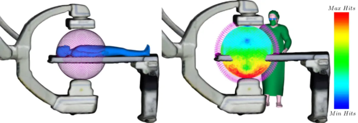
4.2.2 Visualization of simulated radiation risk maps . . . 64
4.2.3 Experimental validation using dosimeters . . . 65
4.2.3.1 Validation methodology . . . 65
4.2.3.2 Results and discussion . . . 67
4.3 GPU-accelerated radiation simulation . . . 70
4.3.1 Simulation approach . . . 71
4.3.1.1 Patient exposure . . . 71
4.3.1.2 Staff exposure . . . 74
4.3.1.3 Scattered radiation propagation . . . 77
Table of Contents
4.3.2.1 Clinician exposure validation . . . 77
4.3.2.2 Evaluation with experimental measurements . . . 79
4.4 Conclusions . . . 80
5 Intuitive visual feedback of ionizing radiation 83 5.1 Augmented reality visualization of ionizing radiation . . . 85
5.1.1 Benefits of X-ray radiation’s AR visualization . . . 85
5.1.2 Visualization methods . . . 86
5.1.2.1 3D propagation of scattered radiation . . . 86
5.1.2.2 Patient exposure visualization . . . 89
5.1.2.3 Staff exposure visualization . . . 89
5.2 Augmented Reality visualization approaches . . . 90
5.2.1 Ceiling-view AR visualization . . . 91
5.2.2 Mobile AR using a hand-held screen . . . 91
5.2.3 Mobile AR using a HoloLens . . . 92
5.3 Conclusions . . . 96
6 Optimization of an X-ray imaging device’s pose 99 6.1 C-arm positioning assistance . . . 101
6.1.1 Context . . . 101
6.1.2 Related work . . . 102
6.2 Imaging device’s pose optimization . . . 103
6.2.1 Problem statement . . . 104
6.2.2 Fast computation of cost function . . . 105
6.2.2.1 Patient exposure term v . . . 106
6.2.2.2 Clinical staff exposure term h . . . 106
6.2.3 Optimization approach . . . 107
6.2.4 Imaging device’s re-positioning in clinical application . . . 107
6.3 Experiments in a simulated environment . . . 109
6.3.1 Experimental setup . . . 110
6.3.2 Optimization algorithm evaluation . . . 111
6.3.3 Cost function weights trade-off analysis . . . 113
6.3.4 Evaluation of the cost function computation approach . . . 115
6.4 Evaluation with dose measurements . . . 117
6.4.1 Experimental setup . . . 117
6.4.2 Evaluation results . . . 119
6.5 Discussion and conclusions . . . 120
III Applications, conclusions and perspectives 123 7 Clinical applications 125 7.1 XAware-Live: a global radiation awareness system . . . 126
7.1.1 General description of the system . . . 126
7.1.2 System’s features and visualizations modes . . . 128
7.1.3 Demonstrations and feedback about the system . . . 129
7.1.4 Future developments . . . 130
7.2 Potential clinical applications . . . 131
7.2.1 Intraoperative radiation awareness . . . 131
7.2.2 Clinical applications of a C-arm pose optimization approach . . . . 133
7.3 Conclusions . . . 134
8 Conclusions and perspectives 135 8.1 Conclusions . . . 135
8.2 Perspectives . . . 138
List of Publications 143 IV Appendices 145 A Radiation dose information 147 A.1 Radiation dose measurements . . . 147
A.1.1 Conversions between radiation dose units . . . 147
A.2 Radiation dose values, thresholds and occupational limits . . . 148
A.2.1 Radiation dose values for common exams . . . 148
A.2.2 Radiation exposure thresholds . . . 148
A.2.3 Dose limits as recommended by the International Commission on Radiological Protection (ICRP) . . . 149
A.3 Radiation exposure metrics . . . 149
B xawAR16 dataset 151 B.1 A multi-RGBD camera dataset for camera relocalization evaluation in the operating room . . . 151
B.2 Dataset description . . . 152
B.3 Optical tracking system calibration . . . 153
B.4 Additional information . . . 153
C Camera relocalization approach for a markerless mobile AR 155 C.1 Introduction . . . 155 C.2 Method . . . 156 C.2.1 Overview . . . 156 C.2.2 Tracking approach . . . 157 C.2.2.1 Tracking initialization/relocalization . . . 157 C.2.2.2 Frame-to-frame tracking . . . 157
C.2.3 Equipment detection in the OR . . . 158
Table of Contents
C.2.3.2 Ceiling cameras template database . . . 159
C.2.3.3 Moving camera template database . . . 159
C.2.3.4 Occlusion handling . . . 159
C.2.4 Dynamic template database sub-sampling . . . 159
C.3 Evaluation with the xawAR16 dataset . . . 160
C.3.0.1 Evaluation metrics . . . 160
C.3.0.2 System settings . . . 161
C.4 Evaluation Results . . . 161
C.4.1 Equipment detection . . . 161
C.4.2 Moving camera tracking . . . 162
C.4.3 Relocalization . . . 163
C.5 Conclusions . . . 165
D R´esum´e en fran¸cais 167 D.1 Introduction . . . 168
D.2 Radioprotection r´eactive au contexte . . . 170
D.2.1 Perception de la salle op´eratoire par des cam´eras RGBD . . . 170
D.2.2 M´ethodes de simulation des radiations . . . 170
D.2.3 Visualisations des radiations par r´ealit´e augment´ee . . . 172
D.3 Optimisation de la pose d’un capteur plan . . . 175
D.4 Application clinique: XAware-Live . . . 176
D.5 Conclusions . . . 179
D.6 Perspectives . . . 180
List of Figures
1.1 A century of technological improvements in X-ray imaging. . . 3 1.2 Frequency of Interventional Radiology (IR) procedures in 6 EU’s hospitals
reported in [Nikodemov´a 2011] (1.2a) and Strasbourg’s University Hospital IR department (1.2b). . . 8 1.3 Effect of increasing patient abdomen thickness on operator exposure,
courtesy of [Schueler 2006]. The drawings illustrate scattered radiation isodose curves calculated with a phantom simulating abdomen thicknesses. A 5 cm increase almost doubles staff exposure. . . 13 1.4 Use of radiation protection equipment in hospitals in Europe as reported
by [Nikodemov´a 2011]. . . 17 2.1 Toshiba’s Dose Tracking System [Rana 2013, Kuhls-Gilcrist 2017] for the
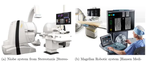
visualization of the cumulative skin dose distribution overlaid over a patient’s generic model during X-ray imaging. . . 23 2.2 Commercially available tele-operated navigation systems for interventional
procedures. . . 28 2.3 Examples of systems providing an enhanced visualization to improve
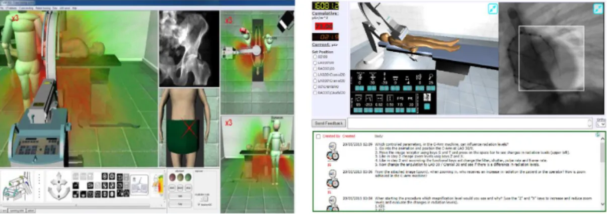
surgical guidance and reduce radiation exposure. . . 31 2.4 Examples of computer-based training systems to teach about C-arm
oper-ation and radioper-ation exposure. . . 35 2.5 Systems for providing feedback of radiation exposure for increasing
clini-cians’ awareness. . . 38 3.1 Views from a multi-RGBD camera system installed in an experimental
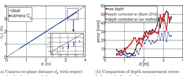
interventional room at IHU Strasbourg, featuring an Artis Zeego X-ray imaging device (Siemens Healthcare, Forchheim, Germany). . . 43 3.2 Evaluation of the depth measurement error and of depth correction
ap-proaches. . . 47 3.3 Registered multi-camera system for performing a 3D reconstruction of an
3.4 Background subtraction approach to track the 3D positions of clinicians in an interventional room and provide a visualization of their current full-body exposure. . . 50 3.5 Courtesy of [Kadkhodamohammadi 2017b]: (left) the detected clinician’s
upper-body poses on an image from an interventional room at Strasbourg’s University Hospital and (right) the simulated radiation exposure per body joint (modeled as water spheres), where red indicates higher dose. . . 51 3.6 (Left) Real-time person pose estimation using the approach from [Cao 2017],
and its usage for the visualization of the body radiation exposure of clini-cians (right). . . 52 3.7 Automatic detection of the X-ray imaging device configuration from views
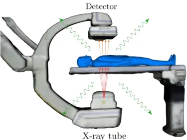
of the ceiling-mounted multi-camera system. . . 54 4.1 Representation of the X-ray imaging process and simulated output
radiog-raphy. . . 57 4.2 Visualization of the X-ray source position and nomenclature for imaging
projections in the transverse plane (left) and in the sagittal plane (right). The position of the source is represented by the red circle with an arrow pointing in the direction of the X-ray beam. . . 60 4.3 Simulated X-ray spectrum (85 kV - 0.4 mm Al filtration) using the online
X-ray spectra simulator from Siemens [Siemens Healthcare 2017b]. . . 62 4.4 Simulation model and setup of the experimental validation. . . 64 4.5 2D Isomaps obtained by summing the radiation risk maps along the x-axis
for two imaging configurations (red indicates higher dose). . . 65 4.6 Position of the dosimeters with respect to the C-arm isocenter (S) for the
two sets of experiments presented. . . 67 4.7 Patient’s energy and dose maps simulated for an Anterior-Posterior (AP)
X-ray projection, 70 kV tube tension, 0.4 mm Al spectrum 8➦ of aperture angle. . . 73 4.8 Generation of scatter maps and their use for a fast computation of a
clinicians’ radiation exposure. . . 75 4.9 Generation of scatter maps and their use for a fast computation of a
clinicians’ radiation exposure. . . 76 4.10 (Left) Results of the simulation of a clinician’s energy for a full rotation of a
C-arm in the Left Anterior Oblique (LAO)/Right Anterior Oblique (RAO) plane computed with a Monte Carlo (MC) simulation, using pre-computed Phase-Space File (PSF) or using scatter maps. (Right) Experimental setup for the experimental validation with measurements from dosimeters in an OR. . . 80 5.1 AR visualization of the 3D propagation of scattered radiation (left) and
of a clinician’s full-body exposure (right), during a RAO at 135➦ X-ray imaging projection. . . 83
List of Figures 5.2 AR visualization of the 3D diffusion of scattered radiation for two imaging
projections: an RAO at 120◦ projection (left) and a Posterior-Anterior (PA) projection (right). Red indicates higher dose. . . 87 5.3 AR visualization of the propagation/intensities of scattered radiation for
two C-arm angulations (AP and LAO at 90◦), illustrating the effect of table- and ceiling-suspended protective shields for radiation protection. . 88 5.4 AR visualization overlaid a posteriori for visualization purposes, to show
the scattered radiation that would be generated if the X-ray device was used in such a situation: no lead protective shields (left) and with a ceiling-suspended shield (right) (Strasbourg’s University Hospital). . . . 89 5.5 Visualization of a patient radiation exposure (to skin and organs) on a
virtual environment (left) or through a mobile AR (right), for an RAO at 135➦ C-arm projection. . . 90 5.6 (Left) Mobile AR visualization of a clinician’s exposure during a PA
projection. (Right) Ceiling-view AR visualization of the exposure of two clinicians for an AP projection. . . 91 5.7 Mobile AR visualization for radiation awareness using a hand-held screen.
The user visualizes the propagation of scattered radiation for the current device configuration directly in his own view. . . 93 5.8 Using Microsoft’s HoloLens to display radiation exposure information. . . 95 5.9 HoloLens visualization of a clinician’s body-part exposure: the person’s
pose is computed in images from a ceiling-camera and transmitted wirelessly. 95 5.10 Virtual Reality (VR) radiation training application: a virtual interventional
scene is displayed to the user with information related to radiation safety through a HoloLens for learning purposes. . . 96 6.1 X-ray imaging device’s pose optimization concept: from an initial
con-figuration, considering clinician, imaging and patient parameters, a rec-ommended device’s pose lowering patient/staff radiation exposure and maintaining the visibility of the targeted anatomical structure in the output image is computed through an optimization loop. . . 99 6.2 “Desired View” pipeline from [Fallavollita 2014]: the user chooses the
desired outcome image and, based on simulated X-rays from pre-operative Computed Tomography (CT) data, the system computes the required positioning of the imaging device. . . 103 6.3 Parametrization of an angiographic C-arm: a projection is determined by
the angles θ (right/left anterior oblique) and φ (caudal/cranial). Tube-to-isocenter distance (TID) (tube-to-Tube-to-isocenter distance) and Tube-to-detector distance (TDD) (tube-to-detector distance) determine the image’s magni-fication. . . 104
6.4 Pose optimization pipeline: from an initial nominal projection Cnom, our
approach suggests a close configuration Copt for which the radiation
expo-sure of staff and patient is reduced. A simulated X-ray image along with exposure reduction statistics are displayed to the operator for him/her to decide to adopt or not the recommendation. If the device’s Applica-tion Programming Interface (API) is available, its re-posiApplica-tioning can be performed automatically through inverse kinematics. . . 109 6.5 Virtual setup illustrating the two clinicians’ scenario for the experiments
presented in sections 6.3.2 and 6.3.3. . . 112 6.6 Trade-off analysis when varying the weights (α, β) from cost function 6.1. 114 6.7 (Left) Setup for the dose measurements performed in a hybrid OR at
IHU Strasbourg using a Siemens’ Artis Zeego X-ray imaging device and RaySafe dosimeters. (Right) Four dosimeters taped to a drip rod used to obtain dose measurements over a “dummy” clinician’s body. . . 118 6.8 Images captured by our ceiling-mounted multi-camera system during the
dose measurements performed at IHU Strasbourg. The nominal configura-tion (Cnom) and the one recommended by our C-arm pose optimization
approach (Copt) are shown. . . 119
7.1 Graphical User Interface (Graphical User Interface (GUI)) of our radiation awareness prototype system XAware-Live. . . 125 7.2 Clinician tracking in XAware-Live: the 2D body-joints’ positions are
overlaid over the color image (left) and the persons’ 3D positions are shown in a virtual environment (right). . . 127 7.3 Visualization of the patient’s dose to the internal structures and to the skin
for the current X-ray imaging device’s projection and imaging protocol on XAware-Live. . . 128 7.4 AR visualization of the intensities and of the 3D propagation of scattered
radiation for the current C-arm projection with XAware-Live. . . 129 7.5 AR visualization of the current personnel’s body radiation exposure with
XAware-Live. . . 130 7.6 Demonstrations of XAware-Live to our industrial partners (left) and to
IHU Strasbourg’s medical fellow staff (right). . . 130 7.7 Concept of a GUI for an intraoperative tool displaying the current scattered
radiation and patient dose in a virtual environment. . . 132 7.8 Postoperative review of atypical dose events recorded by dosimeters during
an X-ray guided procedure, with an AR visualization of the propagation of scattered radiation during such events. . . 133 7.9 Concept for a preoperative procedure planning application to determine
the optimal C-arm poses yielding the lowest dose to the patient in an upcoming procedure. . . 134
List of Figures B.1 Sample images from the xawAR16 dataset recorded with three RGBD
cameras (two ceiling-mounted and a mobile one) in an OR, with ground-truth pose information of the mobile camera. . . 151 B.2 xawAR16 dataset recording setup: Two RGBD cameras are rigidly mounted
to the ceiling (C1 and C2), a third one is fixed to a display (M) held by
a user. A reflective passive marker is attached to the moving camera and its ground-truth pose is obtained with the infiniTrack tracking system. . . 152 C.1 The two steps of our approach for markerless camera relocalization and
tracking, applied for a mobile AR application. . . 155 C.2 Overview of our approach’s workflow. In practice, the data streams from
the cameras (C1, C2 and M ) are processed simultanously by processes
executed on separate threads. . . 157 C.3 Estimated mobile AR display ’s trajectories with our tracking approach,
compared to the ground-truth trajectories for two sequences of the dataset.164 D.1 Chirurgie mini-invasive guid´ee par fluoroscopie au service de radiologie
interventionnelle du Nouvel Hˆopital Civil de Strasbourg. . . 169 D.2 Positions des trois cam´eras RGBD qui sont install´ees au plafond d’une
salle op´eratoire exp´erimentale au IHU Strasbourg (en rouge). . . 171 D.3 Vues du syst`eme multi-cam´era utilis´e pour percevoir la salle op´eratoire. . 171 D.4 M´ethodes de simulation Monte Carlo de la propagation 3D des radiations
et des doses au patient et personnel m´edical. . . 172 D.5 Visualisation par AR de la propagation en 3D du r´etrodiffus´e de radiation,
pour deux angulations diff´erentes de l’imageur: pour une acquisition RAO `
a 120◦ (gauche) et une PA (droite). . . . 173
D.6 Visualisation par AR de la propagation en 3D du r´etrodiffus´e de radiation, pour deux angulations diff´erentes de l’imageur, avec un sans utilisation de protection plomb´ees (suspension plafonni`ere et paravent plomb´e). . . 173 D.7 (Gauche) Visualisation par AR mobile de l’exposition aux radiations des
cliniciens lors d’une acquisition PA. (Droite) Visualisation par AR effectu´ee avec les vues des cam´eras fix´ees au plafond de la salle, illustrant l’exposition de deux cliniciens lors d’une acquisition AP. . . 174 D.8 Visualisation de la dose aux organes et `a la peau du patient calcul´ee avec
nos m´ethodes de simulation Monte Carlo. . . 174 D.9 M´ethode d’optimisation de la pose d’un C-arm: `a partir d’une
configu-ration initiale et en prenant en compte les positions actuelles du staff, les param`etres de l’acquisition et du patient, notre m´ethode cherche la configuration optimale qui r´eduit la dose patient/staff tout en conservant la qualit´e clinique de l’image. . . 176 D.10 Concept pour l’interface utilisateur d’une application de planning pr´eop´eratoire
pour d´eterminer les configurations optimales de l’imageur qui minimisent la dose au patient. . . 177
D.11 Visualisation par r´ealit´e augment´ee de la propagation et intensit´e du r´etrodiffus´e de radiation pour l’angle d’incidence courant du capteur plan, propos´ee par le syst`eme XAware-Live. . . 178 D.12 Visualisation de la dose `a la peau et aux organes du patient pour l’angle
d’incidence courant du capteur plan, propos´ee par le syst`eme XAware-Live.178 D.13 Estimation en temps r´eel de la pose des cliniciens pr´esents dans la salle,
grˆace `a l’int´egration de l’approche de [Cao 2017] `a XAware-Live. . . 179 D.14 Visualisation par r´ealit´e augment´ee de la dose sur les diff´erentes parties du
corps des cliniciens pr´esents dans la salle pour l’angle d’incidence courant du capteur plan, propos´ee par le syst`eme XAware-Live. . . 179
List of Tables
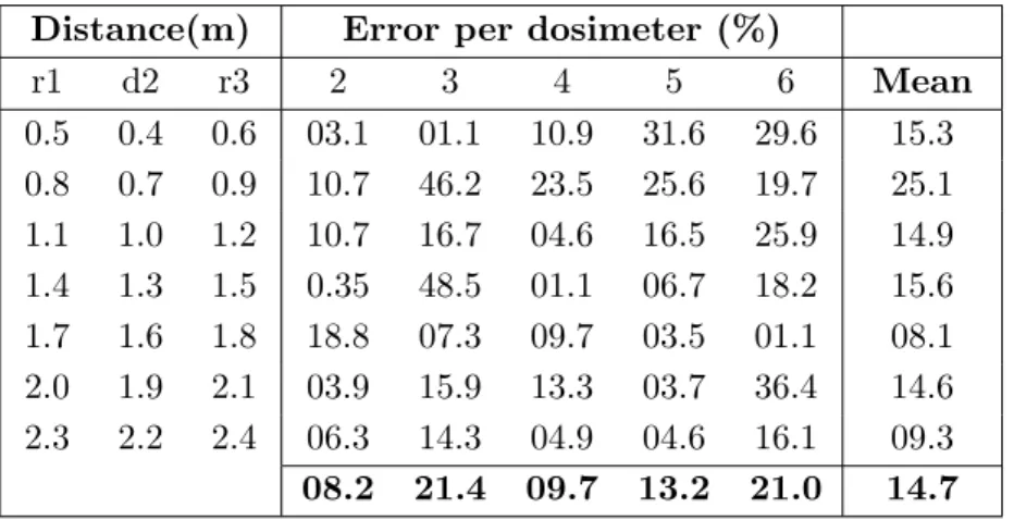
4.1 Simulation errors for the configuration test when using dosimeter 1 for calibration. . . 68 4.2 Mean simulation errors per validation dosimeter and per configuration for
the tube parameters’ test, when calibrating with dosimeter 6 and 8. . . 68 4.3 Mean simulation errors per irradiation protocol when calibrating with
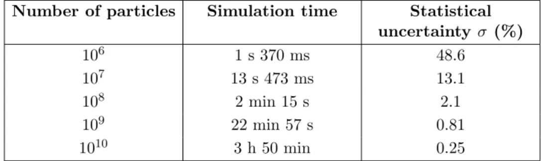
dosimeter 6 and 8 in the tube parameters’ test. . . 69 4.4 Patient radiation exposure maps: simulation times and mean statistical
uncertainty in function of the number of particles emitted. . . 74 4.5 Simulation times of clinician exposure with the three approaches evaluated:
a full Monte Carlo simulation (MC) without approximations, with pre-computed PSF and scatter maps. . . 78 4.6 Mean relative difference of a clinician’s exposure obtained with the PSF
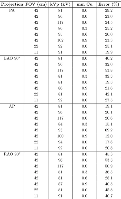
and scatter maps methods, compared with a full MC simulation and pre-computed PSF as references. . . 79 4.7 Mean simulation errors per irradiation protocol with two calibration
dosimeters. . . 81 6.1 Imaging configurations typical in interventional radiology procedures
eval-uated with our approach along with the considered ranges for the sets S. . . 111 6.2 Optimization of the X-ray device’s pose with two algorithms: greedy
best-first search and gradient descent. A scenario with two clinicians is considered, where clinician #1 is at position T1 = [−1000, 0, 0]T and #2
at T2 = [700, 0, 500]T. The recommended configuration Copt, the relative
exposure reduction of the patient (∆v) and of both clinicians (∆h), along
6.3 Results of the optimized C-arm’s pose for each S and comparison with the computation of function (6.1) with no approximations (Full MC ). The absolute difference of Ours and Full MC (Diff ), the recommended configuration Copt, the achieved relative exposure reduction ∆f and the
execution times are provided. . . 116 6.4 Device’s pose optimization with two clinicians in the scene, where clinician
#1 is at position T1 = [−1000, 0, 0]T and #2 at T2 = [700, 0, 500]T. The
recommended configuration Copt, the relative exposure reduction of the
patient (∆v(%)) and of both of the clinicians’ heads (∆h1 and ∆h2) are
provided. . . 117 6.5 Evaluation of the C-arm pose optimization approach with real dose
mea-surements: the evaluated configuration pairs (Cnom, Copt), the relative
clinician exposure reduction as computed from the dose measurements (∆h (measured)) and as predicted by the optimization approach (∆h
(simulated)) along with the absolute difference (Diff.) between them are provided. . . 120 A.1 Typical organ radiation dose from various radiologic studies, as reported
in [Brenner 2007], [FDA 2010] and [Conti 2014]. . . 148 A.2 Threshold doses for potential radiation exposure effects, as reported in
[Miller 2005]. . . 148 A.3 Dose Limits Recommended by the ICRP in [ICRP 2017]. . . 149 B.1 Evaluation dataset: each sequence is categorized according to the side
of the operating table where the mobile display was held, the type of sequence (Smooth, Clinician, Challenging or Device rotation) and the ongoing X-ray device projection. The average rotation velocity (deg/s) and translation velocity (m/s) is also provided. . . 154 C.1 Absolute Pose Error (APE) when relocalizing with different template
databases. Non-filtered : templates generated from synthetic views covering the full sphere of viewpoints around the object. Filtered : sets where a priori information has been used to filter-out irrelevant views. User tracking: using the detected user’s position to load the templates to match. The number of training views as well as the mean translation error (T) in mm, rotation error (R) in degrees, detection speed (S) in seconds and mean values for all the evaluated sequences are provided. . . 162 C.2 Evaluation of our full approach on all sequences from the dataset with the
evaluation metrics described in C.3.0.1. The number of evaluated frames (Ev. frames) corresponds to the frames with ground-truth available. Mean errors per sequence type (Smooth AR display’s trajectories or Challenging for sequences including occlusions, clinicians and/or large/sudden camera viewpoint changes) are provided. . . 163
List of Tables C.3 Evaluation of our relocalization approach compared to Iterative Closest
Point (ICP) with initialization: Ev. Frames is the number of frames per sequence where a relocalization was performed and which also has ground-truth available. We evaluate by computing APE on the relocalized frames (T for the translation error in mm and R for the rotation error in degrees). %Rel corresponds to the percentage of recovered frames (APE within 15 cm in translation and 7➦ in rotation). . . 165
List of Abbreviations
AEC Automatic Exposure Control. 13, 61
ALARA As Low As Reasonably Achievable. 15, 104
AP Anterior-Posterior. xii, xiii, xv, 8, 60, 65, 66, 68, 69, 72, 73, 87, 88, 90, 91, 96, 148, 153, 161, 174
APD Active Personal Dosimeter. 15, 26, 27, 69, 119 APE Absolute Pose Error. xviii, xix, 160, 162–165
API Application Programming Interface. xiv, 49, 52, 54, 55, 109, 126–128, 131, 137 AR Augmented Reality. i, vii, viii, xii–xv, xviii, 18, 19, 30, 35, 37, 39, 54, 83–92, 96, 97,
128–131, 133, 136, 138, 151, 153, 155–158, 160, 162–166, 168–170, 172–174, 177 CAT Computed Axial Tomography. 8
CAUD Caudal. 60, 79, 81, 104, 127
CBCT Cone-Beam Computed Tomography. 31 CRAN Cranial. 60, 79, 81, 104, 127
CT Computed Tomography. xiii, 3, 6–9, 15, 30, 59, 60, 72, 90, 101–103, 107, 110, 139, 148, 170
DAP Dose Area Product. 16, 25–27, 38, 139, 150
DICOM Digital Imaging and Communications in Medicine. 52 DRR Digitally Reconstructed Radiograph. 34, 57
ERCP Endoscopic Retrograde Cholangio-Pancreatography. 7 EVS Endovascular Surgical Neuroradiology. 7
FOV Field of View. 13, 52, 63, 66
GPU Graphics Processing Unit. 19, 32, 34, 36, 58, 70, 71, 73, 77, 78, 80–82, 105, 110, 127, 131, 136, 137, 139, 160, 161, 170, 172, 175
GUI Graphical User Interface. xiv, 125–128, 131, 132, 134 HMD Head-mounted Display. 93, 94, 96, 138
IC Interventional Cardiology. 7, 10, 12, 14, 16, 18, 27, 32, 35 ICP Iterative Closest Point. xix, 49, 53, 157–159, 163–165
ICRP International Commission on Radiological Protection. viii, xviii, 12, 16, 25, 149 II Image Intensifier. 49
IR Interventional Radiology. xi, 7, 8, 16–18, 32, 33, 88
LAO Left Anterior Oblique. xii, xiii, 60, 66, 68, 69, 78–81, 87, 88, 104, 127, 153 MC Monte Carlo. xii, xvii, 32–34, 39, 68, 70, 73, 74, 76, 78–80
MIS Minimally Invasive Surgery. 5, 6, 9, 18, 20, 30, 101 MRI Magnetic Resonance Imaging. 6, 7, 141
OR Operating Room. i, viii, xii, xiv, xv, 5, 19, 20, 24, 34, 38, 44, 47, 52, 54, 58, 62–64, 77, 80, 85, 86, 91, 92, 94, 95, 101, 103, 105, 117–121, 126, 127, 129, 131, 136–138, 141, 151, 158, 165
OST-HMD Optical See-Through Head-Mounted Display. 85, 93, 94, 96, 131
PA Posterior-Anterior. xiii, xv, 37, 60, 63, 65, 66, 68, 69, 80, 87, 90, 91, 94, 96, 148, 153, 161, 173, 174
PET Positron Emission Tomography. 7–9, 15 PSD Peak Skin Dose. 150
PSF Phase-Space File. xii, xvii, 74, 75, 77–80
PTA Percutaneous Transluminal Angioplasty. 6, 8, 14 RAK Reference Air Kerma. 25, 149, 150
RAO Right Anterior Oblique. xii, xiii, xv, 60, 66, 68, 69, 76, 78–81, 83, 85, 87, 89, 90, 104, 127, 153, 173
List of Abbreviations RGBD Red-Green-Blue-Depth. i, vi, ix, xi, xv, 19, 20, 30, 31, 37, 43–45, 48, 50–54, 62, 65, 70, 79, 84, 86, 91, 92, 94, 126, 132, 136, 151, 152, 156–158, 161, 165, 167, 168, 170–172, 176, 180
RPE Relative Pose Error. 160, 162, 163
SLAM Simultaneous Localization and Mapping. 151–153 SPECT Single Photon Emission Computed Tomography. 8 TDD Tube-to-detector distance. xiii, 104
TID Tube-to-isocenter distance. xiii, 104
TLD Thermoluminescent dosimeters. 15, 16, 26, 27, 70 VR Virtual Reality. xiii, 94, 96, 138
Part I
1
Clinical motivation and context
To keep the body in good health is a duty... otherwise we shall not be able to keep our mind storing and clear. – Gautama Buddha
(a) The first known X-ray image, taken from R¨ontgen’s wife left hand [Reed 2011].
(b) Three-dimensional volume-rendered CT image depicting normal coronary arteries [Kuchynka 2015].
Chapter Summary
1.1 X-ray imaging in today’s medicine . . . 5 1.1.1 Minimally invasive procedures . . . 5 1.1.2 Interventional surgical procedures . . . 6 1.1.3 X-ray imaging modalities . . . 7 1.2 Exposure to ionizing radiation during X-ray guided procedures . . . 9 1.2.1 Radiation exposure risks . . . 9 1.2.1.1 Effects of ionizing radiation on living tissue . . . 10 1.2.1.2 Risk to patients . . . 10 1.2.1.3 Risk to healthcare providers . . . 11 1.2.2 Factors affecting radiation propagation . . . 12 1.3 Strategies to reduce radiation dose to patients and clinical staff . . . 14 1.3.1 Radiation safety guidelines . . . 15 1.3.2 Reduction of the imaging device’s effective doses . . . 15 1.3.3 Radiation exposure monitoring . . . 15 1.3.4 Protective equipment . . . 16 1.4 Summary and thesis overview . . . 18 1.4.1 Summary of the medical context . . . 18 1.4.2 Contributions . . . 18 1.4.3 Outline . . . 20
The use of X-ray based medical imaging has revolutionized the diagnostic of diseases and the practice of numerous surgical treatments. It has also been a key factor in the paradigm shift from traditional to minimally invasive surgery. Nowadays, X-ray imaging is fundamental to several fields of medicine such as interventional radiology/cardiology, orthopedics, urology, neuroradiology and radiation therapy to name a few. Even if it is hard today to envision medicine without having the capacity to visualize internal structures and bones through X-ray imaging, X-rays were discovered just slightly more than a century ago. It was in 1895 that Wilhelm Conrad R¨ontgen performed the first radiography (shown in figure 1.1a) while working with a cathode-ray tube in his laboratory at W¨urzberg University in Germany [Reed 2011]. The discovery of this new kind of ray, which could penetrate the body and give the capability to record its inner structure without any visible damage, is considered one of the most momentous events in science and medicine. It was not hard for R¨ontgen’s contemporaries to see the enormous potential of such a discovery. Only a month after, radiographs were being produced in the United States as well as in Europe; within 6 months after this discovery, they were being used at the frontline in battlefields to help locate bullets in wounded soldiers [Reed 2011]. Other advances came quickly such as the invention of the fluoroscope by Thomas Edison and the appearance of contrast agents to further look within body structures. Even though a sea
1.1. X-ray imaging in today’s medicine of technical developments has been made ever since R¨ontgen’s first radiography, there is a core issue related to X-ray imaging which still remains the same even a century later. We refer to the risks associated with the exposure to the ionizing radiation generated during the image acquisition process. At first, there was understandably very little concern about the unintended consequences that could occur from the use of these invisible rays. But after some time, workers exposed to X-rays noted that repeated exposures seemed to make hair fall out, cause skin inflammations, sores, loss of limbs and even death [Linton 1995]. It took several years for scientists to realize that X-rays’ shorter wavelength than light’s along with their high energy could penetrate and break chemical bonds in living tissues, which results in the alteration of the structures and functions of cells [Reed 2011]. Indeed, much of the early collection of information related to radiation damage was gained at great personal expense. However, the large efforts of scientists to develop radiation safety protocols, to devise protection methodologies, to learn to control and assess X-ray production are also considered a major progress in this century of X-ray imaging history [Linton 1995].
In this dissertation, we propose methods to contribute to the effort that radiation scientists have performed throughout the past century to decrease the risks of exposure to ionizing radiation when X-rays are used for medical purposes. We focus on modern applications of X-ray imaging, namely on the use of X-rays for guidance during minimally invasive procedures. In the following sections, we discuss about minimally invasive X-ray guided interventions, including the different image modalities which are used. Then, we present the negative effects associated with the exposure to ionizing radiation, along with a description of the current radiation protection practices. The last section of this chapter provides an overview of the work carried out throughout this thesis to improve radiation safety in the operating room (OR) and also presents the outline of this dissertation.
1.1
X-ray imaging in today’s medicine
In order to improve patient care, surgical procedures are evolving to become minimally invasive. As a consequence, medical imaging devices are now fundamental to the performance of today’s procedures. In this section we first give an overview of the growth of minimally invasive surgery (MIS). Then, we introduce interventional procedures, a kind of MIS generally involving important doses of ionizing radiation. We close this section with a summary of the imaging modalities used in MIS and which cause radiation exposure.
1.1.1 Minimally invasive procedures
Driven by last decades’ significant technological improvements in medical and imaging equipment, minimally invasive procedures (also known as MIS) are progressively replacing traditional open surgery procedures in today’s hospitals [Nikodemov´a 2011]. Open surgery requires a large incision and can incur significant trauma to soft tissue, which can be painful for the patient, can take more time to heal and can lead to potential complications.
Minimally invasive surgery encompasses imaging and catheterization techniques that limit the size of the needed incisions. Reported benefits of MIS include less pain for the patient, reduced risk of infections, quick recovery time and reduced blood loss [Fuchs 2002]. Furthermore, MIS is also associated with decreased postoperative complication rates and shorter hospital stays, which can lead to reduced healthcare costs [Xu 2015]. Therefore, these kinds of procedures are used by a rapidly growing number of healthcare providers in a wide range of medical specialties.
MIS was pioneered in the 1960’s by interventional radiologists. They introduced techniques such as injecting arteries with dye, visualizing these via X-ray imaging and introducing catheters to open up blockages, with the aim of finding safer and better ways to treat atherosclerotic vascular diseases [Lakhan 2009]. Such developments not only led to the replacement of conventional procedures with minimally invasive ones, but also stimulated surgeons to reevaluate conventional approaches. For instance, coronary artery stent insertion became rapidly a more popular alternative than the traditional coronary artery bypass, and from 1996 to 2000 its rate of performance doubled from 157 to 318 per 100,000 adults in the United States [Miller 2005]. In Europe, the number of interventional cardiovascular procedures increased from 350,000 in 1993 to more than 1 million in 2001 [Picano 2013].
The spectrum of minimally invasive procedures performed today is extremely large. They are typically classified according to the means used for guidance and visualization of the interior of the patient’s body. On the one hand, endoscopic, laparoscopic and arthroscopic procedures rely on the use of a camera inserted through a small incision or through natural orifices, enabling to get live color images of the inside of the patient. On the other hand, interventional and several orthopedics procedures are performed using medical imaging devices such as fluoroscopic X-ray systems, Computed Tomography (CT) or Magnetic Resonance Imaging (MRI) scanners for guidance and visualization of internal anatomical structures. Interventional procedures, presented in the following section, are becoming more frequent and complex and are the focus of this thesis. This is due to the fact that several reports have documented that the dosage of ionizing radiation among interventional physicians is the highest registered by any medical staff using X-rays [Roguin 2013].
1.1.2 Interventional surgical procedures
Because of the many aforementioned benefits of minimally invasive procedures, both their popularity and complexity have increased in the past years. This is directly connected to the technological progress in highly sophisticated imaging equipment used for these purposes, which enables clearer visualizations of fine internal anatomical structures of the patient (see Figure 1.1b). Nowadays, in European countries more than 400 types of X-ray guided interventional procedures are identified, with a 12 % increase in the number of procedures performed every year [Nikodemov´a 2011]. Furthermore, 657,000 fluoroscopy guided percutaneous transluminal angioplasty (PTA) procedures were performed in adults in 2002 in the United States [Miller 2005], with a tendency to increase in the
1.1. X-ray imaging in today’s medicine following years.
Interventional practices are nowadays most common in the fields of interventional cardiology (IC), radiology (IR) and neuroradiology. IC is the specialized branch of cardiology performing conventional coronary angiography, stenting and other procedures on coronary arteries, along with various kinds of therapies to unblock clogged arteries sup-plying blood to the heart, to stop heart attacks and/or relieve chest pain [Lakhan 2009]. The duties of IR practitioners are more varied. These include the performance of an-giographies on other peripheral arteries (renal, popliteal, femoral...) and the use of percutaneous access to treat diseases or perform biopsies [Lakhan 2009]. The results of a study on the frequency of IR procedures in six different EU countries (see Figure 1.2a) presented in [Nikodemov´a 2011], indicate that angiographies are just half of IR practitioners’ workload; the other half corresponds to embolization and Endoscopic Retrograde Cholangiopancreatography (ERCP) procedures. Interventional neuroradiol-ogy (also known as Endovascular Surgical Neuroradiolneuroradiol-ogy (EVS)) is a subspecialty of radiology also making use of minimally invasive catheter-based technology and radio-logic imaging to treat and diagnose diseases of the central nervous system, head, neck and spine [Lakhan 2009]. Common EVS interventions include treating carotid artery stenosis, intracranial/extracranial aneurysms and performing vertebroplasty/kyphoplasty procedures.
All interventional procedures hitherto mentioned rely on the use of medical imaging equipment for diagnosis or therapy delivery (X-ray devices, CT, MRI, Positron Emission Tomography (PET) scanners, and/or ultrasound probes). Several of these devices generate ionizing radiation during the imaging process, and, therefore, cause risks of radiation exposure to patients and clinicians. Such risks vary according to the complexity of the procedure. Hence, as the frequency, complexity and diversity of interventional procedures is increasing, so is the radiation dose to patients and healthcare personnel [Miller 2005]. Indeed, interventional practitioners are performing more procedures than ever, which usually last longer, resulting in more exposure to radiation than in the past [Roguin 2012]. Studies [Roguin 2013] have reported that the dosage of ionizing radiation among interventional practitioners are the highest registered for any medical staff using X-ray, especially since most of interventional procedures are performed under fluoroscopy guidance (continuous X-ray imaging). Additionally, staff is obliged to remain close to the patient during interventional procedures, therefore, their exposure to radiation cannot be fully avoided. This can be observed in Figure 1.2b, which shows an example of a fluoroscopy-guided interventional procedure performed by an interventional practitioner at Strasbourg’s University Hospital.
1.1.3 X-ray imaging modalities
There exist many types of medical imaging modalities, each relying on different technolo-gies and techniques. Ultrasound imaging makes use of high frequency sound waves to visualize soft tissues, such as muscles and internal organs. MRI relies on radio waves and magnetic fields to produce images. Unlike ultrasound and MRI, projection radiography
(a)Digital Subtraction Angiography (DSA), Percu-taneous Transluminal Angioplasty (PTA), Carotid (Ca), brain (Ce), lower limbs (LL) and renal arter-ies (Re) angiographarter-ies.
(b) Interventional room at the Strasbourg’s University Hospital during the execution of a fluoroscopy guided vertebroplasty.
Figure 1.2: Frequency of IR procedures in 6 EU’s hospitals reported in [Nikodemov´a 2011] (1.2a) and Strasbourg’s University Hospital IR department (1.2b).
(commonly called standard X-ray), CT, fluoroscopy, and nuclear medicine procedures all rely on ionizing radiation to generate images of the body [FDA 2010]. We discuss relevant facts about these imaging modalities below.
Projection radiography procedures, which include chest X-rays and mammography, involve relatively low amounts of radiation (a typical chest X-ray exposes the patient to 0.02 mSv1 [Conti 2014]). During a CT scan (also called a CAT scan) a rotating source
passes X-rays through a patient’s body to produce several cross-sectional images of a particular area. These two-dimensional images can also be digitally combined to produce a single three-dimensional image for better visualization. Hence, organ doses from CT scanning are considerably larger than those from corresponding conventional radiography. For instance, a conventional anterior-posterior (AP) abdominal X-ray results in 0.25 mSv of equivalent dose, which is at least 50 times less than the corresponding stomach dose from an abdominal CT scan [Brenner 2007].
Continuous X-ray imaging or live fluoroscopy is the preferred modality among inter-ventional practitioners since it allows to image the surgical site in real-time and gain a better 3D understanding. This is useful to observe the movement of an object or substance inside the patient’s body. When fluoroscopy is continuous, around 30 X-ray images per second are obtained and as a consequence the amounts of radiation generated are significantly higher [Kaplan 2016]. Pulsed fluoroscopy obtains 1 to 6 images per second and can be a less irradiating alternative, yet, it does not allow clinicians to benefit from the same real-time feedback.
Other procedures involving radiation are nuclear medicine procedures, such as PET or Single Photon Emission Computed Tomography (SPECT) examinations. These are relevant imaging techniques that provide functional and quantitative information about
1.2. Exposure to ionizing radiation during X-ray guided procedures the organ of interest for diagnostic and therapeutic applications. A patient is given a small amount of a radioactive substance, called a radiopharmaceutical or radiotracer, and a detector outside the body is then used to obtain an image of the radioactive material as it moves throughout the body [FDA 2010]. The extremity dose of workers in nuclear medicine can be a concern since the procedures require the handling of radiopharmaceuticals at contact and/or very close to the extremities (hands and fingers) [Vanhavere 2008]. According to the literature, technicians working in PET facilities receive slightly higher doses than those working in conventional diagnostic nuclear medicine departments, however, these doses are generally below the limits [Vanhavere 2008]. In general, the doses involved in nuclear medicine procedures are significantly smaller than during a fluoroscopic intervention or a CT scan [FDA 2010].
Because CT, fluoroscopy, and nuclear medicine procedures involve repeated or ex-tended exposure to ionizing radiation, they are associated with a higher radiation dose than projection radiography. Among these modalities, interventional fluoroscopy is the one which causes the highest exposure to clinical staff and, for several kinds of procedures, to the patient too [FDA 2010]. Due to the excellent image quality of CT images, these are rather used for pretreatment imaging and treatment planning. Despite providing the ability to see structures in 3D, CT is not often used for direct guidance since its real-time performances are not as high as fluoroscopy’s [Wong 2008]. Indeed, no post-processing or reconstruction is required for fluoroscopy, so users can see in real-time changes in the patient or the transit of tools and catheters inserted into the patient. Also, the CT scanner environment offers less work area that fluoroscopy because of the large gantry. Therefore, fluoroscopy is preferred for intraoperative guidance during interventional procedures, which highly exposes clinical staff and patients to ionizing radiation.
1.2
Exposure to ionizing radiation during X-ray guided
procedures
The benefits of X-ray guided MIS come at a price: the exposure to ionizing radiation of staff and patient. While a patient’s exposure can be justified by medical indication and usually happens in a single episode, medical staff providing patient care can be chronically exposed for many years on a daily basis. In this section, we discuss the risks of exposure to ionizing radiation for patient and clinical staff during X-ray guided procedures. We also describe the many factors that affect radiation’s magnitude and propagation, which render the monitoring of exposure complex to achieve.
1.2.1 Radiation exposure risks
Recent studies have reaffirmed the hypothesis that any radiation dose carries with it an associated risk of negative biological effects and that such a risk increases with an increasing dose [Roguin 2013]. Indeed, it is generally accepted that there is no low dose threshold, namely no amount of ionizing radiation should be considered absolutely safe [Miller 2005]. Negative effects of radiation exposure are classified in two categories:
deterministic and stochastic. On the one hand, deterministic effects occur once a dose threshold has been exceeded and their severity increases with the magnitude of the dose. The most common are skin and eye injuries. Stochastic effects, on the other hand, come with no minimal threshold dosage and their adverse outcomes, such as cancer, can take up to several decades to manifest. The likelihood of stochastic effects increases with the total radiation energy accumulated over time, but the severity of such effects is independent of the dose [Kirkwood 2014].
Studies have reported the average dose of a patient in IC to range from 10 to 50 mSv per procedure [Morrish 2008]. On average, a coronary angiography exposes the patient to a dose equivalent to 300 chest X-rays, and a cardiac radiofrequency ablation to 750 chest X-rays [Picano 2013]2. Effective staff/operators dose range from 0.02 to 30 µSv [Morrish 2008], and can reach higher values for complex procedures, such as up to 200 µSv in a single endovascular thoracoabdominal aneurysm repair [Picano 2013]. However, the repetitive nature of staff’s exposure, even when the dose is low, increases the long-term risk of developing negative biological effects. The most active interventional cardiologists can have an annual exposure equivalent to around 5 mSv (under the lead apron) per year, which is two to three times higher than diagnostic radiologists’ exposure [Picano 2013]. We discuss more thoroughly radiation exposure risks for patient and clinical staff below, after explaining radiation’s effects on living tissue.
1.2.1.1 Effects of ionizing radiation on living tissue
X-rays are electromagnetic radiation of the same nature as light but with a much shorter wavelength. This shorter wavelength is what gives them the capability of penetrating materials that light cannot, such as living tissue [Reed 2011]. The damage caused by the exposure to ionizing radiation occurs at the cellular level and rapidly replicating cell components such as DNA and cell membranes are the most susceptible to be damaged [Kaplan 2016]. Since these electromagnetic waves are of high energy, they have the ability to break chemical bonds, which may incur in both direct and indirect damage. Direct damage occurs as energy is absorbed and molecular bonds are broken, which can result in cell necrosis or distorted replication (deterministic effects). Indirect damage occurs when water molecules are ionized into free radicals. This has the ability of disrupting bonds, and it is thought to be responsible for the long-term effects of radiation, namely stochastic effects [Kaplan 2016].
1.2.1.2 Risk to patients
In the case of patients, the benefits of a proper usage of X-ray devices (either for diagnosis or therapy), outweighs the experienced radiation risks, especially in the older age groups [Roguin 2014]. The patient is exposed to primary radiation, namely radiation between the X-ray source and the image intensifier. Short-term risks are
radiation-2More statistics about radiation doses for common X-ray examinations can be found in appendix A.2.1.
1.2. Exposure to ionizing radiation during X-ray guided procedures induced skin damages (erythema, epilation and even dermal necrosis)3, which result
from acute radiation doses beyond 2 Gy [Miller 2005]. The extent of the injury may not be apparent for weeks and repeated procedures increase the risk of skin damage, since previous exposures sensitize the skin. At lower dose, exposure to the eye lens can cause lens opacity and cataracts that can take years before manifesting. Long term effects include the potential risk of cancer, which for patients is less common since in most cases they are not exposed repetitively to radiation.
1.2.1.3 Risk to healthcare providers
During the X-ray imaging process, X-rays which are not absorbed or do not interact with any material on their path, are deflected and continue their trajectory with an attenuated energy. Such a pattern of deflection, known as scattered radiation or scatter, produces a field of radiation which is responsible for most of clinical staff’s exposure [Kaplan 2016]. Therefore, occupational exposure is directly linked to patient dose since it results from this secondary scattered radiation that is produced. Moreover, the exposure of clinicians performing X-ray guided interventional procedures cannot be fully avoided due to the required proximity to the patient, the complexity of the procedure and the need for performing a large set of acquisitions with varying parameters [Schueler 2006]. As mentioned earlier, reports have documented the dosage of radiation among interventional physicians as the greatest registered among any medical staff working with X-rays [Roguin 2013]. As highlighted by [Picano 2013], cumulative doses after 30 years of working life are in the range of 50 to 200 mSv, corresponding to a whole-body dose equivalent of 2,500 to 10,000 chest X-rays.
Even if most of the clinicians’ body is shielded with lead protective clothing (see section 1.3.4), studies have shown that the dose delivered to unprotected body parts such as hands, eyes and legs, can approach the maximum established limits [Nikodemov´a 2011]. Especially the hands are at danger since these remain close to the patient i.e. close to the radiation source. Indeed, skin doses to the hands can reach 1 mSv per procedure and can even be higher if bad practices are followed [Carinou 2011]. A rise in reported skin changes on the hands, and an expected increase in late effects such as lens injuries, cataracts and possibly cancer have been reported in [Miller 2005]. Additionally, results from a study of reported cases of brain cancers among interventional cardiologists have shown that in 85 % of the studied cases, the malignancy was located in the left side of the brain [Roguin 2013]. This is due to the usual layout of an interventional room where the practitioner operates from the right side of the patient, thus, the scatter radiation comes predominantly from the patient on his/her left side [Picano 2013]. Clinicians’ heads can be at best incompletely protected and annual head exposure among interventional cardiologists has been reported to be nearly 10 to 20 times higher than the whole-body dose recorded below apron [Roguin 2013, Picano 2013]. Concerning eye exposure, studies have found a dose-dependent increased risk of posterior lens
opacities for interventional cardiologists and nurses during IC procedures [Roguin 2012]. Indeed, eye cataracts can be observed in one-third of staff after 30 years of work in IC departments [Picano 2013]. It was recently reported that exposure to the eye lens may induce lens opacities and cataracts at substantially lower adsorbed doses than previously considered. As a consequence, the threshold for radiation-induced cataracts has been revised from 2 to 0.5 Gy [Omar 2017]. Furthermore, the International Commission on Radiological Protection (ICRP) has recently recommended a reduction of the occupational dose limit for the eye lens from 150 mSv to 20 mSv, averaged over 5 years, with no single year exceeding 50 mSv [Principi 2016]. Ionization radiation exposure also affects the reproductive health of exposed clinicians. Reports highlight that the cumulative gonad dose (below the lead apron) for interventional cardiologists is in the range of 0.5-1 Sv over a professional lifetime of 30 years, and this can cause significant risks of reproductive health problems [Picano 2013].
The common radiation protection principles with regard to time, distance, and shielding are difficult for operators to fully implement in interventional procedures due to examination complexity, the required proximity between clinician and patient, and the need to maintain a sterile field [Schueler 2006]. Increases in interventional procedures’ difficulty, volumes, and workload per clinician contribute to increase the risk of appearance of adverse outcomes for staff exposed to scattered radiation [Roguin 2012]. Therefore, exposure to ionizing radiation during such interventions is further becoming a concern for healthcare providers.
1.2.2 Factors affecting radiation propagation
The propagation of X-rays and their interactions with matter are complex phenomena. Hence, large-scale efforts have been performed to develop methodologies and tools for better understanding the factors affecting it, either through large dose measurement campaigns (e.g. ORAMED project4 [Nikodemov´a 2011]) or by means of computer-based simulations [Koukorava 2011, Santos 2015, Principi 2016]. A patient is exposed to the primary X-ray beam, hence, his/her exposure depends on: the imaging parameters (tube voltage (kV), current (mA), collimation...), his/her own physical characteristics (sex, body weight, age...) and the irradiated region of the body. However, occupational exposure is more challenging to assess since staff is mostly exposed to the photons scattered by the patient, table and/or equipment, and also because the propagation and magnitude of such a scatter are affected by several simultaneously changing factors [Koukorava 2011]. Some of them, such as the patient’s characteristics (e.g. abdominal thickness) or the complexity of the procedure, are beyond clinicians’ control. For instance, complex procedures requiring long fluoroscopy time and higher tube current, such as complex endovascular procedures, incur in higher potential dose [Kirkwood 2014]. Also, it has been reported
4ORAMED was a large consortium-based collaborative project (2008-2011), supported by the European Commission within its 7th Framework Program, aiming at the development of methodologies for better assessing and reducing radiation exposure to medical staff performing interventional procedures [ORAMED 2011].
1.2. Exposure to ionizing radiation during X-ray guided procedures that operators’ body height has a major impact on the amount of scatter radiation to different parts of their body [Picano 2013]. Other factors, such as the personnel’s position with respect to the patient, the imaging parameters or the disposition of protective equipment can be partially controlled but are usually altered during the procedure. Indeed, many studies can be found in the literature on the influence of the different risk factors of staff/patient exposure. We discuss below some relevant examples:
Patient size For patients with a thicker layer of adipose tissue, the automatic exposure control (AEC) of modern X-ray equipment increases the tube’s voltage in order to compensate for the increase of beam attenuation by the patient’s body, with the aim of producing clinically useful images [Santos 2015]. Such an increase of the source’s potential results in scattered X-rays with higher energy, and, as a consequence, in a significant increase in the levels of scattered radiation [Schueler 2006]. This can be observed in figure 1.3, where the scatter values at the level of the operator’s legs are almost doubled for a 5 cm increase of a patient’s abdominal thickness [Schueler 2006].
(a) Scatter levels calculated with a phantom of 29 cm of thickness.
(b) Scatter levels calculated with a phantom of 34 cm of thickness.
Figure 1.3: Effect of increasing patient abdomen thickness on operator exposure, courtesy of [Schueler 2006]. The drawings illustrate scattered radiation isodose curves calculated with a phantom simulating abdomen thicknesses. A 5 cm increase almost doubles staff exposure.
X-ray imaging parameters Parameters of the image acquisition protocol, such as the field-of-view (FOV) size, the tube tension (or kilovoltage) and the beam filtration, significantly affect radiation dose. A larger FOV enables to visualize a larger region of a patient’s anatomy in the image. However, the doses are higher since more scatter is produced and a larger part of the patient is irradiated [Koukorava 2011]. Moreover, adding filtration (e.g. copper spectral beam filtration) to the X-ray beam reduces both the patient dose and the levels of scatter [Schueler 2006]. Yet, the use of copper filtration will reduce the proportion of low energy photons and can degrade image contrast. X-ray source position During a procedure, a radiographer operates the X-ray imaging device according to instructions from the operating surgeon or the clinical radiologist, for acquiring the right image for navigation or therapy delivery. This is achieved
through changes in the X-ray beam projection (also known as angulation). Changing the angulation means changing the position of the X-ray source with respect to the patient, and thereby has a significant effect in both patient and staff dose. Indeed, studies have shown that the highest rate of scatter is always produced between the X-ray source and the patient (i.e. backscattering effect) [Carinou 2011]. Hence, it is commonly recommended to keep the X-ray source below the table (undercouch) since both the patient dose and scatter levels are lower. In such configurations, the patient’s spine and the surgical table result in a beam filtration of low energy photons. This contributes to decrease the intensity of the transmitted radiation and to lower the energy values absorbed by the sensitive organs located in the patient’s thoracic region [Santos 2015]. Operator dose is also significantly lowered as opposed to the case when the source is above the operating table (overcouch). Indeed, in overcouch configurations, the dose to the clinicians’ eyes and hands can be up to 6 times higher [Koukorava 2011]. This is due to the fact that in such projections, X-rays are scattered above the table. If no ceiling-mounted shields are used, sensitive body-parts (head, thyroid, eyes...) of the attending personnel can be dangerously exposed. This is why many recommendations to avoid such configurations can be found in the literature [Carinou 2011].
Operator’s position Staff must avoid standing close the X-ray source during the imaging process as the levels of scattered radiation are the highest [Carinou 2011]. In several IC procedures such as angiographies and PTA, radial access has become a more popular approach than femoral access since this approach has been shown to reduce complication rates and hospital stay [Ertel 2012]. However, radial access requires longer fluoroscopy times and a closer positioning of the operator to the X-ray source [Carinou 2011]. A comprehensive study reported the operator’s doses to be 5-7 times higher than when standing in the position for femoral access [Nikodemov´a 2011]. In general, the operator’s distance to the patient’s skin entrance site is crucial because the level of scatter radiation is inversely proportional to the distance squared (inverse-square law) [Picano 2013].
1.3
Strategies to reduce radiation dose to patients and
clin-ical staff
X-ray imaging has many important clinical uses and can provide significant benefits. This is why the healthcare professional community seeks to support the benefits of medical imaging while reducing the risks. To this end, several major strategies have been adopted and the most common ones are herein described5.
![Figure 1.4: Use of radiation protection equipment in hospitals in Europe as reported by [Nikodemov´ a 2011].](https://thumb-eu.123doks.com/thumbv2/123doknet/14449548.518377/44.892.154.738.750.996/figure-radiation-protection-equipment-hospitals-europe-reported-nikodemov.webp)
![Séminaire pluridisciplinaire[BR]- La participation à un séminaire sur une thématique fiscale pointue [BR]- Séminaire pluridisciplinaire : "Utilisation de la scission partielle pour séparer activité commerciale et patrimoine immobilier."](data:image/gif;base64,R0lGODlhAQABAIAAAP///wAAACH5BAEAAAAALAAAAAABAAEAAAICRAEAOw==)