IX. COMMUNICATIONS RESEARCH
A. MULTIPATH TRANSMISSION
Prof. L. B. Arguimbau J. Granlund E. H. Gibbons, Jr. W. L. Hatton
J. L. Hummer 1. Speech and Music
a. Theory
The main emphasis on the project has been temporarily shifted from laboratory work. An effort is being made to justify the non-rigorous
treatment of interference given in earlier reports. In addition, the inter-ference between more than two paths is being studied. J. Granlund
b. Receiver Design
In the last report a short discussion of commercial FM receiver per-formance was given. No attempt was made to localize the source of the rela-tively poor interference suppression.
Since that time the limiter section of the laboratory receiver has been used in conjunction with a commercial discriminator having the usual 200-kc bandwidth rather than the 6-Mc used in the laboratory receiver. It has been found that the removal of residual limiter failures in a commercial
receiver does not materially improve the overall performance. The combina-tion of a poor limiter and a wide-band discriminator has not yet been given a conclusive trial, although design work in connection with the laboratory receiver indicates little hope for good results with a poor limiter.
J. L. Hummer 2. Television
In designing television systems, a useful criterion of performance is the response of the system to a step-function change in light. For video amplifiers and picture and camera tubes, the step-function response has been well investigated. This is also true of the radio-frequency stages, which in an AM system are subjected to a carrier wave modulated by a
step-function.
However, in an FM system, the radio-frequency stages are subjected to changes in frequency. In this case, if the response of one circuit (output frequency and amplitude) to a step-function in frequency is known, the response to any other input frequency change or to the overall response of cascaded circuits cannot be found by a simple application of superposition.
(IX.
COMMUNICATIONS RESEARCH)
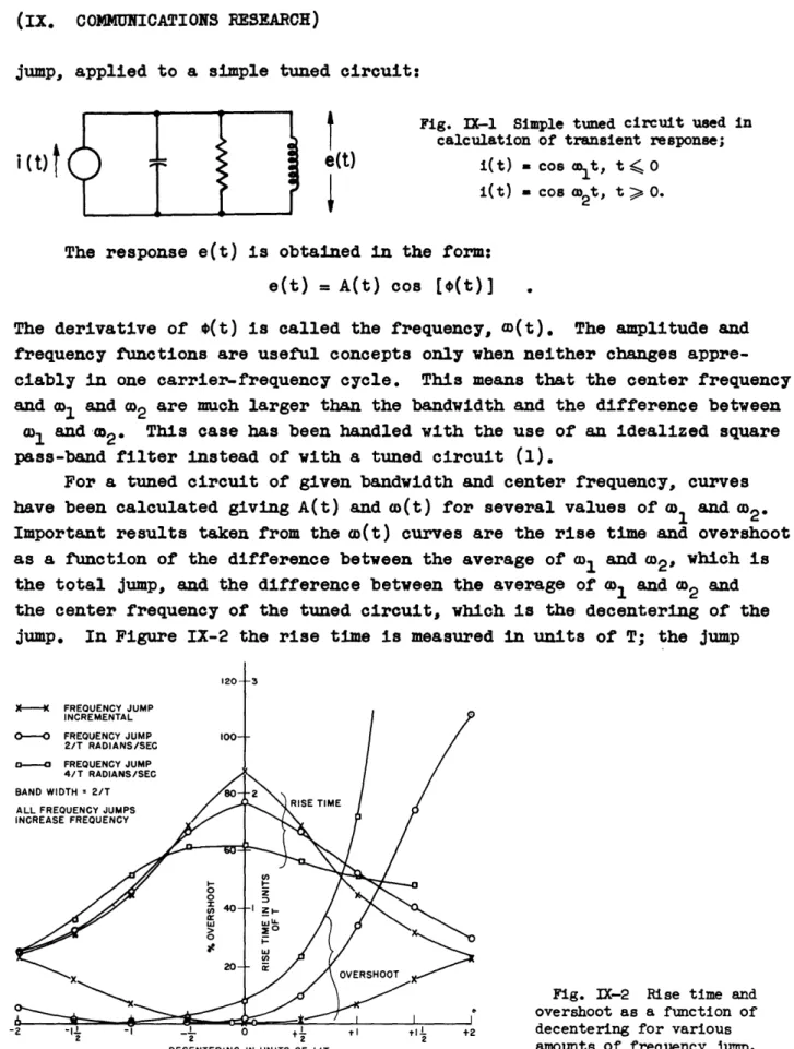
jump, applied to a simple tuned circuit:
e(t)
3)f
Fig. IX-1 Simple tuned circuit used in calculation of transient response;i(t) . cos Cot, t < o
i(t) = cos a2t, t > 0.
The response e(t) is obtained in the form:
e(t) = A(t) cos [4(t)]
The derivative of *(t) is called the frequency, w(t). The amplitude and
frequency functions are useful concepts only when neither changes
appre-ciably in one carrier-frequency cycle. This means that the center frequency and
wl
and c02 are much larger than the bandwidth and the difference between>l and 2. This case has been handled with the use of an idealized square
pass-band filter instead of with a tuned circuit (1).
For a tuned circuit of given bandwidth and center frequency, curves have been calculated giving A(t) and (t) for several values of 1 and 2e Important results taken from the w(t) curves are the rise time and overshoot as a function of the difference between the average of 01 and £02, which is the total jump, and the difference between the average of wlI and w02 and the center frequency of the tuned circuit, which is the decentering of the
jump. In Figure IX-2 the rise time is measured in units of T; the jump
Fig. IX-2 Rise time and
overshoot as a function of
decentering for various
DECENTERING IN UNITS OF I/T 8amounts or frequency jump.
i (t)
t
_ _=!
(IX. CO14UNICATIONS RESEARCH)
and decentering are measured in units of 1/T. T is the video time constant of the circuit, or the reciprocal of the half bandwidth. The curve for zero jump is the limiting curve as the ratio of jump to bandwidth approaches zero,
Note that for a finite jump the curves are not symmetrical with respect to the decentering. The overshoot depends on the position of 2, and when m2 is at the center frequency of the tuned circuit there is no overshoot.
Attempts have been made to solve the problem for transitions from
I1
to w2 with finite rate. Input frequency functions of the following forms
have been tried:
1.
w(t) =
O
1t < 0
e(t) = C2
2-
1)e-at t > 0
e2 -(w12 (t)-
.D
2 .
+
t
0
OD(t)
2 - OD 02 w0l t >o
3.
W(t) -l
t
0o
'
2-
'1
(t) - c2 -1 t o(1 + t)
4. w(t) = 0o + 1/2 Amtanh (at) for all t
The response e(t)
has
been obtained for case 1, but o(t) and A(t)
have not yet been obtained since the expression for e(t) involves complex
incomplete '-functions. W. Hatton
B. MICROWAVE MODULATION TECHNIQUES
L. D.
Smullin
J.
Jensen
1. Investigation of Frequency Modulation of a Reflex Klystron
This investigation has been completed and prepared as a master's thesis
in
M.I.T.
Electrical Engineering Department by
J.
Jensen. The work will
also be summarized in the next Progress Report.
(IX. COMMUNICATIONS RESEARCH)
C. STATISTICAL THEORY OF COMMUNICATION
Prof. J. B. Wiesner E. E. David, Jr. Prof. W. B. Davenport, Jr. L. Dolansky Prof. R. M. Fano A. J. Lephakis Prof. Y. W. Lee L. Levine
T. P. Cheatham, Jr. H. E. Singleton C. A. Stutt
1. Auto-Correlation Functions a. Correlation Functions
This work will be covered in forthcoming Technical Report No. 122 by
T. P. Cheatham, Jr.
b. Digital Electronic Correlator
Construction of the digital correlator has been completed, and minor changes are being made preparatory to placing it in operation. A full description of the correlator will be given in a forthcoming technical
report. Y. W. Lee, H. E. Singleton, L. G. Kraft, Jr. 2. Amplitude and Conditional Probability Distributions
of a Quantized Time Function
The zero-crossing pulse generator has been completed and tested. This unit generates pulses whose amplitudes are determined by the zero-crossing
periods of the voice wave. The output pulses of this unit vary over a range of 60 volts (and thus vary over 60 levels as measured by the level selectors) corresponding to a range of zero-crossing period from about fifteen micro-seconds to twenty millimicro-seconds. Data obtained with this unit indicate that the range is adequate. With the completion of the unit, all of the proposed equipment for this study has been completed and is working satisfactorily. It is expected that any further work on equipment design and construction will be confined to minor modifications.
The major portion of the data taken has been confined to the study of the probability distributions of the voice wave instantaneous amplitude. Only enough data has been taken on the voice zero-crossing periods to deter-mine the suitability of the equipment characteristics.
A study has been made of the minimum length of speech sample required to give data which adequately represent the stationary statistical proper-ties of the voice wave. The results indicate that a three-minute sample
-50-X
NORMALIZED
INSTANTANEOUS
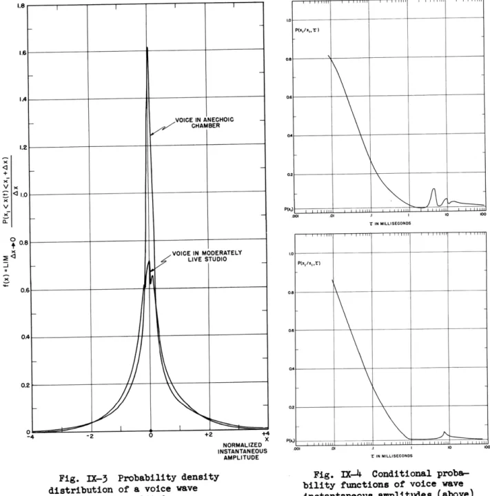
AMPLITUDE Fig. IX-3 Probability density
distribution of a voice wave instantaneous amplitude.
T IN MILLISECONDS
t IN MILLISECONDS
Fig. IX-4 Conditional proba-bility functions of voice wave instantaneous amplitudes (above) female voice, (below) male voice.
(IX. COMMUNICATIONS RESEARCH)
will give results to within + 5 percent of the long time results, for all but the largest and smallest ranges of amplitude. For the extremal values, the sample length must be two or more times this minimum value.
A study has also been made of the probability density distribution of the voice wave instantaneous amplitude. This distribution has been studied for several different voices; both for the case of negligible acoustical reflections, and for the case of the reflections present in a rather live studio. Figure IX-3 shows the effect of reflections on this distribution. Both curves are for the same voice reading the same material, and both are normalized to have rms values of unity. Curves of this type show the neces-sity of specifying the physical environment of the voice being studied.
Certain conditional probabilities concerning the voice wave instanta-neous amplitude have been studied. One probability studied is
P(x1
xl,
)
= P[ 1 <
x(t
+ ) < x +
AxI
x
<
x(t)
<
x
I
+
Ax]
;
(I)
that is, the probability that the voice wave at a time t + T lies in the interval (xl, X1 + Ax) conditional upon the occurrence of the voice wave at the time t in the same interval. This probability is studied as a function of T. Presuming the voice wave to be a continuous function of time, this probability should be nearly unity for very small values of T, and for large values of 7 should equal the unconditional probability
P(xl) - P(x1 < x(t) < xI + Ax) . (2)
Figure IX-4 shows two curves of this type: one for a female voice and the other for a male voice. Both voices were studied in an anechoic chamber and both read the same material. The minor peaks in the range of one to ten milliseconds apparently correspond to average vowel-pattern repetition periods, i.e. to average pitch periods. This phenomenon is being studied further.
Upon completion of the above study, investigation of the voice wave zero-crossing periods will be started. W. B. Davenport, Jr.
3. Techniques of Optimum Filter Design
As was mentioned in the last Progress Report, it is sometimes desirable to approach the problem of synthesis of Wiener optimum-transmission-systems from a prescribed impulse response, rather than from a prescribed frequency response. For this reason a rather extensive study has been made to deter-mine the nature of this impulse response h(t) and to develop methods for
obtaining h(t) from experimental data, which are usually given in the form
(IX. COMMUNICATIONS RESEARCH)
of correlation functions.
Briefly, it has been shown that h(t) will consist of two parts: (1)
a
series of singularity-type functions occurring at, or initiated at, t
-0
and t
=
a, where a is the delay time of the system; and (2)
a continuous
part tending to zero as t tends to infinity. In the present method, the
evaluation of the continuous part is facilitated by approximating it with
a set of orthonormal functions; consequently, the complete expression for
h(t) may be written in the form:
N
N
L
h(t) = aj Ui(t ) + j U (t - a)+ an t ,
i=-M
J=o
n=o
where the Ui(t) and Uj(t - a) are impulses, integrals of impulses, or
deriva-tives of impulses, depending on whether i and j are zero, negative integers,
or positive integers, respectively, the set
fn(t)
is orthonormal, and ai,
Aj, and an are constant coefficients.
Pertinent results relative to a consideration of the impulse response
h(t) are itemized below.
1. Proof of the existence of singularity functions in
the impulse response of optimum systems.
2. Connection between the impulse responses of optimum
systems with zero delay to systems with finite delay.
3.
Criterion based on correlation functions and their
derivatives for determining which singularity functions
of the type Un(t) and Un(t - a), n = 0,1,2..., arepresent in the
impulse
response.
4.
Criterion for establishing which singularity functions
of the type U.n(t), n = 1,2,3..., are present in the
impulse response.
5.
Methods for obtaining the coefficients al
1Bj,
and an
in the expression for h(t).
Work on the above considerations of the impulse response is essentially
complete, and attention is now being given to setting up suitable filter
problems which may be used in an experimental evaluation of optimum-system
performance. Y. W. Lee, C. A. Stutt
4. STORAGE OF PULSE-CODED INFORMATION
Sufficient storage-system equipment has been constructed to enable one
of the two storage channels to be tested. A storage tube has been obtained,
and tests will be started as soon as the installation of this tube has been
(IX. COMMUNICATIONS RESEARCH)
completed. It is expected to have the complete system in operation by the time this report is published.
The work done up to the present on the information-storage project is described in the master's thesis, "Storage of Pulse-Coded Information",
by A. J. Lephakis which has been submitted.
J. B. Wiesner, A. J. Lephakis
5. "Felix" (Sensory Replacement)
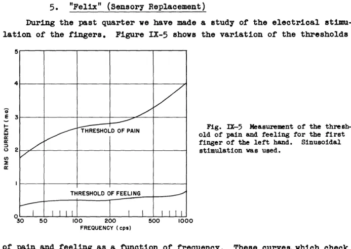
During the past quarter we have made a study of the electrical stimu-lation of the fingers. Figure IX-5 shows the variation of the thresholds
Fig. IX-5 Measurement of the thresh-old of pain and feeling for the first finger of the left hand. Sinusoidal
stimulation was used.
30 50 100 200 500 1000
FREQUENCY (cps)
of pain and feeling as a function of frequency. These curves,which check with Bell Telephone Laboratories' data, are very similar for all fingers. When measured on a current basis the thresholds of five people were con-sistent to within a small percentage. On the basis of voltage applied to the electrodes, the thresholds have a tendency to be more erratic. This work would indicate that electrical stimulation is feasible for "Felix" if a current limiter is inserted.
We have recorded work patterns of the present five-channel unit
photo-graphically to observe if each phoneme has a different pattern. Figure IX-6
shows a typical pattern for the word at. The bottom line is a marker with
an interval of 0.008 second between pips. Above it the five lines represent
the energy in each of five frequency bands, photographed in ascending order
5 4 3 2 -E z a, E 0 THRESHOLD OF PAIN THRESHOLD OF FEELING r:
7
1111 - -- -----(IX. COMMUNICATIONS RESEARCH)
Fig. IX-6 Five-channel transmission of the word at.
Fig. IX-7 Seven-channel transmission of the word at.
with the lowest frequency at the bottom. The five-unit system failed to differentiate the phonemes adequately but it might be satisfactory if ampli-tude variation is included.
A seven-channel unit has provided a unique pattern for each phoneme. Figure IX-7 illustrates the word at. The bandwidths employed here are (reading up): 0 - 200 cps, 200 - 400 cps, 400 - 670 cps, 670 - 1000 cps, 1000 - 1400 cps, 1400 - 2400 cps, 2400 - 15000 cps. The lowest bandwidth (0 - 200 cps) may not be needed. The pictures do not always represent the true pattern recorded by the fingers. There is a minimum time difference that can be distinguished by the nervous system between pulses arriving at
two fingers. If these two pulses arrive with a time difference shorter
than the minimum time, they appear to arrive at the same time. This mini-mum time was found to be about 0.08 second. A phonetic analysis of Figure
IX-7 with allowance for minimum time differentiation is shown in Figure IX-8. J. B. Wiesner, L. Levine
1.0 1.1 1.2
Fig. IX-8 Pattern of seven-channel
unit perceived by the fingers.
_j z z 7 ---5 -4 I / I -0.1 0.2 0.3 0.4 0.5 0.6 0.7 0.8 09 TIME IN SECONDS A I T 1 1 I 1 I I I 1 1 I I I
I IIII
Il
II
I
I
1
]I
irrl
II-(IX. COMMUNICATIONS RESEARCH)
6. Clipped Speech Studies
a. A Short-Time Correlator for Speech Waves
A block diagram of the short-time correlator is given in Figure IX-9.
A delay device having 12 tapping points enables the short-time correlation function to be evaluated at 13 points. At each delay point a multiplier forms the product of the direct speech and the delayed speech. The product is then averaged in an averaging circuit before being sampled by a switch S which supplies the vertical deflection voltage to the cathode-ray-tube display. The horizontal deflection voltage is obtained from a linear time base synchronized with the switch S.
Auto- and cross-correlation functions can be obtained. The delay device used consists of an artificial telephone line of 24 sections with a total delay of 0.001 sec. The cut-off frequency is 7,350 cps and the phase shift is almost linear up to 4000 cps. This line is suitable for a
study of speech of telephone-toll quality.
A block diagram of the correlator showing one channel in detail is given in Figure IX-10.
The speech input common to the thirteen multiplier tubes is modulated by a 456-kc carrier in a balanced modulator. Carrier leak is about -40 db with respect to the modulated speech output. The modulator filter is of wide bandwidth (64 kc) and small delay (11 isec) and is effective in
sup-pressing modulator output terms involving three times the carrier frequency. These terms are the only important distortion terms present in the modulator output. The filter output impedance is reduced in a cathode follower stage for supply of the modulated speech to the thirteen multiplier tubes.
The product is formed in the multiplier tube and, together with the modulated speech, passes through the product filter (tuned to 456 kc) and
the amplifier, and is demodulated in the phase-sensitive detector.
The output-filter serves to form a running average of the product and also to eliminate the speech. The switching circuit comprises a gate tube that is individual to each channel and a gate pulse generator and cathode-ray-tube display common to all of the channels.
One channel of the correlator has been completed and tested. The linearity of the multiplier is illustrated by Figure IX-11. For input voltages not exceeding 0.3volt applied to the direct speech input terminals and 2volts applied to the delayed speech input terminals, the error in the
product does not exceed 10 percent. The effect of phase displacement be-tween the two input voltages when the input is a sine wave of 250, 1000 or
-56-II
~_L__XI(~
~_1IUPICIII_
I_--
LIl
LI11___-_~___II
3 cn I-. 0 >2 o I-o 0
Fig. IX-9 Block diagram of short-time correlator.
DELAYED
SPEECH
INPUT
I 2 3
INPUT TO DELAYED SPEECH INPUT TERMINALS (VOLTS RMS)
INDIVIDUAL CHANNEL EQUIPMENT
Illustration of multiplier linearity.
COMMON EQUIPMENT
Fig. IX-10 Block diagram of one channel
of short-time correlator. SPEECH INPUT COMMON EQUIPMENT Fig. IX-11 -- ,F___ ~
(IX. COMMUNICATIONS RESEARCH)
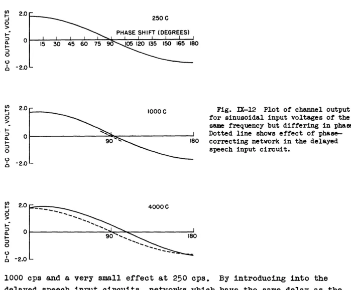
4000 cps is illustrated in Figure IX-12. The delay due to the modulator filter has a marked effect on the curve for 4000 cps input, less effect at
5250 C
PHASE SHIFT (DEGREES)
15 30 45 60 75 0 05120 135 150 165 180
Fig. IX-12 Plot of channel output for sinusoidal input voltages of the
same frequency but differing in phase. Dotted line shows effect of phase-10 correcting network in the delayed
speech input circuit.
1000 cps and a very small effect at 250 cps. By introducing into the delayed speech input circuits, networks which have the same delay as the modulator filter, the effect of the modulator filter delay is eliminated.
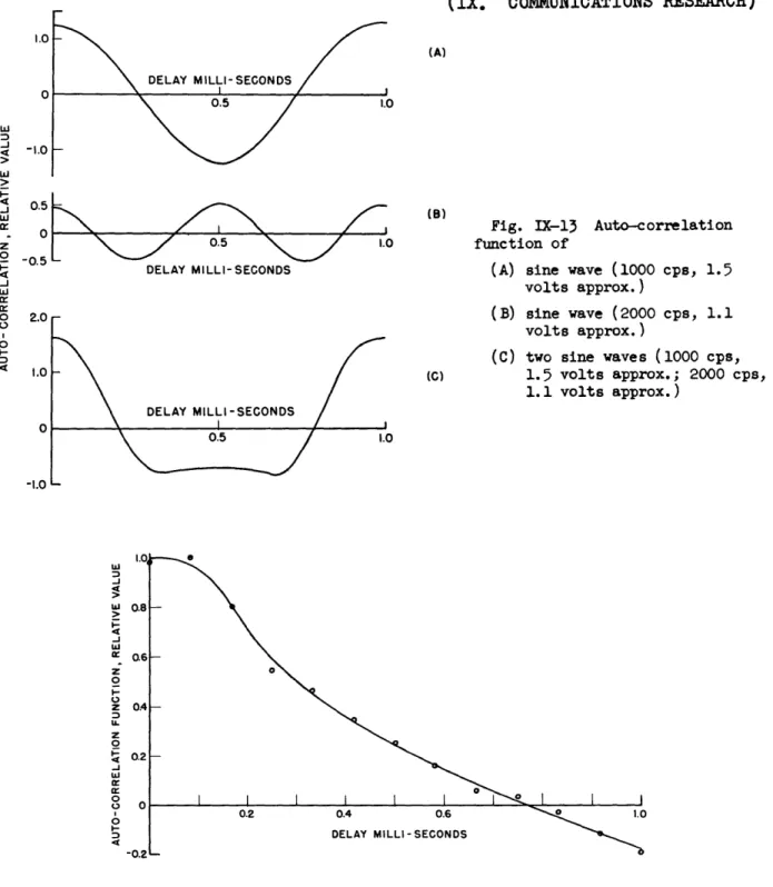
The measured auto-correlation function of sine wave inputs at 1000 cps and 2000 cps are illustrated in Figure IX-13 (a) and (b). With the two input frequencies applied simultaneously, the curve of Figure IX-13 (c) was obtained, providing a further check on the accuracy of the correlator.
Using for the output filter an R-C circuit of time constant 40 sec it was found that the correlator output attained a constant value when the speech input did not contain pauses of undue length. Figure IX-14 shows the auto-correlation function of male speech recorded in a live studio. The measurement of short-time correlation functions awaits the completion of the remaining channels.
-58-2.0 00 a 0 O I -0 0 0f . - .U 0 o I--a 0 0 0 ' (n o a 0 0 -.(IX. COMMUNICATIONS RESEARCH) 0.5 1.0 DELAY MILLI-SECONDS DELAY MILLI-SECONDS 0.5 1.0 L S \.
Fig. IX-13 Auto-correlation
function of
(A) sine wave (1000 cps, 1.5 volts approx.) (B) sine wave (2000 cps, 1.1 volts approx.) -1.0 0.5 -0.5 2.0 t.0 0O DELAY MILLI-SECONDS
Fig. IX-14 The long-time auto-correlation function of male speech recorded in a live studio (one voice only; averaging time about 40 sec).
Further information on the correlator design is contained in a master's thesis, M.I.T. Electrical Engineering Department, 1949, "A Short-Time Cor-relator for Speech Waves", by P. E. A. Cowley.
R. M. Fano, P. E. A. Cowley
DELAY MILLI-SECONDS S1I
0.5 1.0
(C) two sine waves (1000 cps, 1.5 volts approx.; 2000 cps, 1.1 volts approx.) -1.0 0.8 0.6 0.4 0.2 ---0
(IX. COMMUNICATIONS RESEARCH)
7. Pulse-Code Magnetic Recorder
Certain parts of the existing playback apparatus, the amplifier and peaker, have been improved in order to make the operation more reliable.
The erasing problem has been investigated. Several ferromagnetic materials (such as polyiron) were tested. It was finally decided to use
laminations of high-p iron for the erasing head.
A complete coder system, including the timing circuits, was designed and essential parts built for testing. A 3.6-Me oscillator with a pulse-generator provides for the pulses to be counted by a binary counter. The sampling frequency (25 kc) is obtained by a division of the oscillator fre-quency. The time-modulated gate-pulse (gating the continuous pulse train) is derived from the audio input by means of a phantastron delay circuit. Several parts of the coding system are being tested at the present time.
The recording-head problem was investigated mathematically. The resulting relations for the current in the recording head give a rise time of about 10 psec when the entire winding of the recording head is used (250 h). When only one half of the winding is used (70 ph), the rise time is about 5.5 psec. J. B. Wiesner, L. Dolansky
D. TRANSIENT PROBLEMS
Prof. E. A. Guillemin W. H. Kautz Dr. M. V. Cerrillo L. Weinberg 1. Transient Theories
All projects to compute the generalized transient generating functions described in the last two progress reports have been completed, and will be published. Tables, plots, and the properties of Lommel's functions of
two variables will be presented in a separate Technical Report, No. 138, rather than as an appendix to Report No. 55, as originally planned.
During the last three months, work has been concentrated on the preparation of Report No. 55, dealing with the approximate evaluation of integrals of the type
f(t) = F(s) eW(S't)ds
Several refinements of the general theory have been made, and, in particu-lar, the potentialities of continued fractions for certain approximations are being investigated.
-60-(IX. COMMUNICATIONS RESEARCH)
In order to evaluate the above integral, F(s) and W(s,t) must be ap-proximated by simpler functions in certain discrete regions of the s-plane. Single-valued functions of a complex variable are usually approximated by making an expansion of the function about some point in this region, then
terminating this expansion at a finite number of terms. The resulting function is a polynomial if a Taylor expansion is used, or a rational frac-tion if a Laurent expansion is made. The representafrac-tion of a branch of a multivalued function is more difficult, however, because of the discon-tinuous character of the function near the branch cut, since it is necessary to preserve somehow the character of the cut in the approximation so that an integration may be performed along its banks. Both Taylor series and Laurent expansions are very unsatisfactory for this purpose.
If, however, the continued-fraction development of one branch of a multivalued function is terminated after a finite number of partial quo-tients, the discontinuous character of the cut is preserved in the approxi-mation, which is now rational, and, as a rule, much easier to integrate. This cut-preserving property of continued-fraction approximations is a very important and useful property, heretofore neglected as far as the authors are aware.
Very often the functions F(s) and W(s,t) or factors thereof belong to the class of "positive real" functions (2). The continued fraction expan-sion of such functions is most conveniently handled through the medium of their Stieltjes integral representations. Certain results of Herglotz (3), Reisz (4), Cauer (5), Wall (6), and Perron (7) are useful here, but the form in which these mathematicians' work is presented is neither construc-tive from an engineering standpoint nor directly applicable to the problem at hand. A re-interpretation of their conclusions from a more heuristic viewpoint is first necessary. The discussion of the Stieltjes integral representation of "positive real" functions, and some other related topics, originally planned as a short appendix to Technical Report No. 55, has become too voluminous, and will be presented as a separate report, No. 139. E. ACTIVE NETWORKS
Prof. E. A. Guillemin
Dr. M. V. Cerrillo J. G. Linvill
1. General Theory
It may be in order to review briefly at this time some preliminary
(IX. COMMUNICATIONS RESEARCH)
the problem of electrical network synthesis in its broadest aspects,
includ-ing passive and active elements operatinclud-ing under nonlinear as well as linear
conditions, and associated questions of stability.
While in the restricted problem of linear passive network synthesis
the questions of the existence of solutions and of the necessary and
suf-ficient conditions to be satisfied by given data are clearly established,
a similar understanding of the synthesis problem involving active and
non-linear elements is as yet wholly lacking and badly needed. The solution
to this problem is far from being a straight-forward extension of the linear
passive synthesis methods. It is one which will require the adaptation and
application of entirely different mathematical instrumentalities and
tech-niques.
A possible approach to a solution is suggested through recognition of
the fact that one may represent the equilibrium of a linear network
con-taining active elements as that of a passive one in which some of the
varia-bles are subjected to a set of linear constraints. While effective in some
simple cases, the method needs to be further studied to determine its
possi-bilities under more general conditions.
In 1913 Campbell showed that the equilibrium conditions of a linear
passive network can be expressed through minimization of the loss function
associated with that network. This result, which leads to the Kirchhoff
laws expressed in Lagrangian form, is obtained as the solution to an
ordi-nary maximum-minimum problem involving a quadratic form in several variables.
The logical extension of this problem, to include a set of linear
constraints, has mathematically been given, and represents a formal
solu-tion to the active network analysis problem, although only under condisolu-tions
of linear operation. The underlying philosophy, however, suggests a
possi-ble further extension to the more general nonlinear propossi-blem. The function
to be
minimized may
not be the power loss as in the linear case, but in any
event will be some related function expressible as an integral
in
terms of
the pertinent variables.
The natural mathematical tool for the minimization of this integral,
subject to linear or nonlinear constraints, is to be found in the calculus
of variations - more specifically, in the problem of Lagrange or its
equiva-lent as given by Bolza and Mayer.
Be it again stressed that one should not expect any immediate tangible
results from a continued study along these lines. There is much that is
lacking in the way of physical interpretation to make the suggested abstract
mathematical instrumentality meaningful and useful. However, if only some
-62-(IX. COMMUNICATIONS RESEARCH)
clarification is initially given to the question of existence of solutions, the practical implication will be of utmost significance.
E. A. Guillemin, M. V. Cerrillo
F. LOCKING PHENOMENA IN MICROWAVE OSCILLATORS
The work on this project was suspended for the summer months and is
being resumed.
References (1) H. Salinger, Proc. I.R.E. 30, 378 (1942).
(2) 0. Brune, "Synthesis of a Two-Terminal Network Whose Driving-point Impedance is a Prescribed Function of Frequency";
J. Math. Phys. (M.I.T.) 10(3), 191-236 (1931).
(3) G. Herglotz, "Uber Potenzreihen mit positivem reelen Tell
im Einheitskreis"; Leipzig Ber. 6, 501
(1911).
(4) M. Reisz, "Sur le probleme des moments"; Arkif Mat. Ostron. Fysik,
16(12), (1921).
(5) W. Cauer, "Das Poissonsche Integral und seine Anwendung auf die Theorie de linearen Wechselstromschaltungen (Netzwerke)", Elek.