HAL Id: hal-01342568
https://hal.inria.fr/hal-01342568
Submitted on 6 Jul 2016
HAL is a multi-disciplinary open access
archive for the deposit and dissemination of
sci-entific research documents, whether they are
pub-lished or not. The documents may come from
teaching and research institutions in France or
L’archive ouverte pluridisciplinaire HAL, est
destinée au dépôt et à la diffusion de documents
scientifiques de niveau recherche, publiés ou non,
émanant des établissements d’enseignement et de
recherche français ou étrangers, des laboratoires
Isotropic BRDF Measurements with Quantified
Uncertainties
Ramon Hegedus, Antoine Lucat, Justine Redon, Romain Pacanowski
To cite this version:
Ramon Hegedus, Antoine Lucat, Justine Redon, Romain Pacanowski. Isotropic BRDF Measurements
with Quantified Uncertainties. EUROGRAPHICS WORKSHOP ON MATERIAL APPEARANCE
MODELING, Jun 2016, Dublin, Ireland. �hal-01342568�
H. Rushmeier and R. Klein (Editors)
Isotropic BRDF Measurements with Quantified Uncertainties
R. Hegedus1and A. Lucat2and J. Redon2and R. Pacanowski2
1Department of Cognitive Neuroscience, Eberhard Karls University, Tubingen 2LP2N (CNRS) & Institut d’Optique Graduate School & INRIA
Abstract
Image-based BRDF measurements on spherical material samples present a great opportunity to shorten signifi-cantly the acquisition time with respect to more traditional, non-multiplexed measurement methods for isotropic BRDFs. However, it has never been analyzed deeply, what measurement accuracy can be achieved in such a setup; what are the main contributing uncertainty factors and how do they relate to calibration procedures. In this paper we present a new set of isotropic BRDF measurements with their radiometric and geometric uncertainties acquired
within such an imaging setup. We discuss the most prominent optical phenomena that affect measurement accuracy
and pave the way for more thorough uncertainty analysis in forthcoming image-based BRDF measurements. Our newly acquired data with their quantified uncertainties will be helpful for comparing the quality and accuracy of the different experimental setups and for designing other such image-based BRDF measurement devices.
Categories and Subject Descriptors (according to ACM CCS): I.3.3 [Computer Graphics]: Picture/Image
Generation—BRDF Measurements Analysis
1. Motivation and Related Work
Since the seminal work of Marschner [Mar98] or Matusik
et al. [MPBM03] on BRDF acquisition, a lot of devices and
measurement setups have been developed to acquire the ap-pearance of materials.
For the last two decades, most researchers from the Vi-sion or CG communities have focused on acquiring ac-quire more complex appearance functions, such as
spatially-varying BRDF (e.g., [McA02,LBAD∗06]) to Bidirectional
Texture function (e.g., [DvGNK99]) or tried to reduce setups complexity or cost (e.g., [RWS∗11]). Unfortunately, most se-tups or available measurements data are hard to compare be-cause they rely on qualitative validation instead of a
quanti-tative one. For example, many papers (e.g., [NDM05]) that
try to fit BRDF analytical models discard measurements at arbitrary grazing angles because they «seem» unreliable.
We believe that new available data with their quantified uncertainties will be helpful for the research community, es-pecially in order to compare the quality and accuracy of the different experimental setups and even to help other research teams to develop their devices. Furthermore, uncertainty val-ues can be useful to guide approximation techniqval-ues (e.g., Levenberg-Marquardt, SQP, Weighted Least-Square),which are necessary to obtain parameters of analytical models.
This paper presents a new set of isotropic BRDF mea-surements with their radiometric and geometric
uncer-tainties acquired from our imaging device (cf. Section2).
The uncertainties are derived from a model (cf. Section3)
that take into account different source of errors (e.g., focal
length, mechanical, ...). In section4we illustrate through
various plots the different uncertainties obtained with our setup and also illustrate the acquired BRDFs. Finally, we discuss the limitations of our current uncertainty model and offer possible improvements for it.
2. BRDF Setup
Our setup shares similarities from the one introduced by
Ma-tusik et al.. As shown in Figure1in our setup we measure
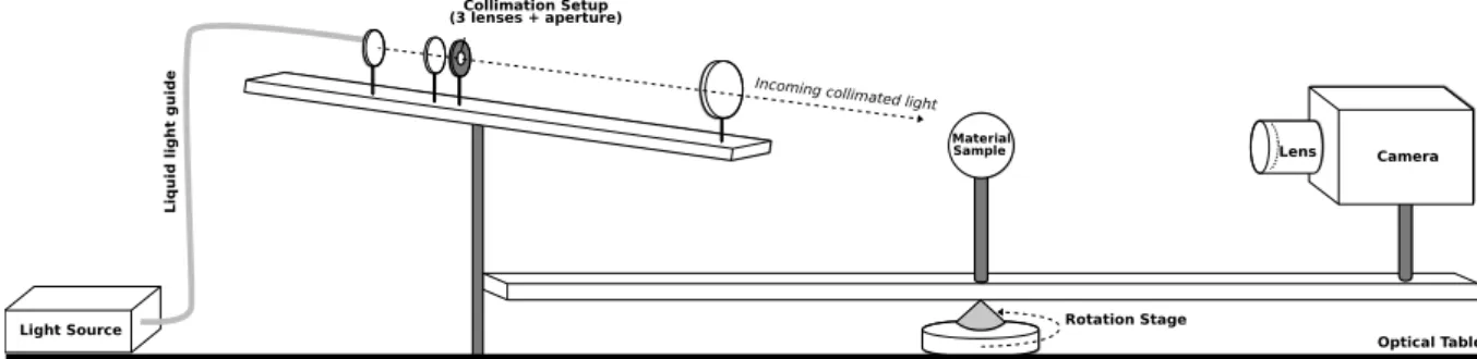
the BRDF of materials on a spherical sample by acquiring multiple images using a Jenoptik scientific camera (ProgRes C14 Plus). The camera is firmly mounted on an arm that is fixed to a rotation stage (from Zaber T-RS60). The material sample (i.e., a target sphere of approx. 6cm) is placed on a support also fixed to the rotating arm. Contrary to previ-ous setups, our light source is a fixed collimated beam that lits the entire target sphere. In another words the camera and the target sphere are always facing each other, regardless of the rotation step. However, they are moving wrt. to the light source thanks to the rotating arm, which makes possible to
R. Hegedus& A. Lucat & J. Redon & R. Pacanowski / Isotropic BRDF Measurements with Quantified Uncertainties Lens Camera Material Sample Collimation Setup (3 lenses + aperture)
Incoming collimated light
Liqui d li ght g uid e Optical Table Rotation Stage Light Source
Figure 1: Schematic view of our acquisition setup.
have the three degrees of freedom required to measure an isotropic BRDF.
The goal of our setup is to measure a spatially uniform
isotropic BRDF. As defined by Nicodemus [NRH∗77], the
BRDF fr is a positive quantity expressed in sr−1 (inverse
steradian) representing how a material reflects angularly the light. For a given point pSon a surface S fris defined as the
ratio of the differential reflected radiance Lrand the di
ffer-ential irradiance dE:
fr(θi,θo,∆φ)=
Lr(θo,φo)
dE(θi,φi)
where all angles (θi,θo,∆φ= |φo−φi|) are expressed in the
local (tangent) frame of the surface orientated with a
nor-mal vector ns. When using a broadband white light source
with an RGB-sensor, the measured BRDF can be seen as an angular function returning an RGB HDR value:
fr(θi,θo,∆φ) → (ρr,ρg,ρb) . (1)
The geometric calibration step is responsible to establish-ing the angular values (θi,θo,∆φ), whereas the radiometric
calibration is necessary for the BRDF values themselves. Geometric Calibration As in Matusik et al. setup, the fact to have a fixed camera with respect to the target sphere presents the advantage to calibrate (geometrically) the cam-era only once. Calibrating the camcam-era is done using the Cal-tech library [Bou] with the associated thin-lens model. This model is also able to take into account distortion, but the calibration process did not compute meaningful values for our camera and therefore we simply discarded these param-eters. The camera calibration allows us to recover the per-pixel view direction as well as the focal length.
The second calibration step is to recover the target sphere position in the camera frame, assuming its radius is known (e.g., provided by the manufacturer). This can be done easily by noticing that a perspective projection of a sphere provides a perfect elliptical contour. Fitting this ellipse directly gives the sphere center, with a very good accuracy.
Finally, in order to recover the light direction (in camera
fr(θi,θo,∆φ) Isotropic BRDF function
ρr,ρg,ρb BRDF RGB values
S Sphere on which the BRDF is measured
θi,θo,∆φ Angles in the tangent frame of S
pS Point on S
ns Normal vector of pS
(rs,cs) Radius and position of the sphere
A Rotation axis of the illumination vector
F Focal length
o Optical axis of the camera
pccd Pixel on the sensor
sccd Size of a pixel (6.45 × 6.45microns2)
Er,g,b(pccd) HDR Values (Irradiance) at pccd
ωo Camera view vector in camera space
φstage Angle of the rotation stage
U(x) Uncertainty function
Figure 2: Mathematical notations used in this paper. Please
refer to Figure4to see how these quantities relate to each
other in terms of uncertainties.
space), we use a mirror sphere as target and record multiple images of the specular highlight visible on the sphere. By assuming a perfect mirror, we compute the reflected ray im-pacting from the light spot for various camera-light configu-rations. This process gives a 3D locus of the light direction, which can be accurately described by a rotation axis and a latitude.
We deduce from the camera calibration and the radius of the target sphere its position wrt. to the camera. Then, we ray-trace a virtual sphere in order to estimate the normal vec-tor in each pixel. Finally, combining the light direction, the view vectors and the per-pixel normal vectors we get an esti-mate, per pixel, of the three angles (θi,θo,∆φ) of an isotropic
BRDF measurement.
Radiometric Calibration We analyzed the radiometric re-sponse of our camera, which is an important factor to con-sider in order that accurate radiance values be measured.
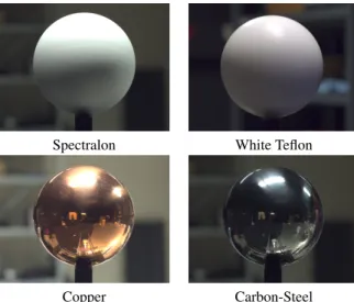
Spectralon White Teflon
Copper Carbon-Steel
Figure 3: The four materials measured for this paper.
Since our setup accommodates a stabilized light source and the camera has an electronic shutter that allows for precise exposure time control, we have chosen a simple, yet effi-cient way of acquiring the response curve. The light was directed towards the camera lens, in front of which a thin diffuser sheet was fixed, thus the same image of the diffused
source light was recorded multiple times with different
ex-posure times. Then the median pixel value in each of R,G,B channels throughout the whole image was selected. In this way median value vs. exposure time directly yields the re-sponse curve, since exposure time is directly proportional to incoming total radiance. These data showed that radio-metric response is totally linear as long as pixel value, en-coded with 14 bits, is less than 15800 (values over 15800 were simply discarded). The other common correction re-lated to color measurements is to make RGB values inde-pendent from the sensor spectral sensor sensitivity and the spectral light composition. This correction procedure can be done using a reference object, in our case a spherical Spec-tralon that is designed precisely to have a uniform spectral reflectance. Imaging this object allows to find the correct multiplicative factors to apply on each color channel in order to recover correct relative (inter-color-channel) values.
Material Samples As shown in Figure3, we acquired four
materials ranging from a very diffuse (Spectralon) to an
al-most perfect mirror sphere made of carbon-steel. We used the carbon-steel ball as reference for the radius, since the manufacturer provides its radius (6cm) with a 50 µm uncer-tainty. For the other material samples, we compute the radius using the carbon steel sphere as a reference. If we replace it by another sphere of unknown radius, we can recover its position and radius by the ellipse fitting method previously described, knowing the depth in the camera frame instead of the radius. We assumed bilateral symmetry (i.e., symmetry
of the BRDF wrt. to the incident plane) of an isotropic BRDF and therefore our setup acquired 221 images (1360x1024 pixels) by moving the rotation arm 0.75 degrees in each step. This resolution gives about 60 million samples for each mea-sured material. More precise measurements can be achieved by reducing the rotation step of the stage (up to. 0.0002 de-gree). However, it is important to keep in mind that the an-gular resolution of the BRDF measurement also depends on
the camera sensor resolution, as it ranges from 0.1◦
resolu-tion for a normal viewing direcresolu-tion to 2◦at 50◦and reaches 12◦for grazing angles. θiis ranging from 0 to 90◦, θofrom 0
to 85◦,∆φ from 0 to 180◦. Finally, all material measurements will be released on the ALTA [BCP∗15] project website.
3. Uncertainty Model
In this paper we are interested in establishing the uncertain-ties σ associated with the BRDF values (σρr,σρb,σρb) as well as with the geometrical positions of the measurements (σθo,σθi,σ∆φ). Figure 4shows how the uncertainties of a BRDF measurement are related to the calibration parameters of the different parts of the setup. Some uncertainties such as the radius of the sphere or the pixel size are directly given by manufacturers. Radii of the spheres were given up to 50µm, whereas the pixel size is known up to 0.005µm. For the me-chanical uncertainty of the rotation stage we verified that the repeatability and uncertainty numbers given by the manu-facturer were correct. In order to increase the precision of the measurement, the stage is always set to rotate only by a discreet number of steps. All other uncertainties are derived from either radiometric or geometric calibration procedure. More formally, the uncertainties σ of a given parameter is a function of the following parameters:
σθi,∆φ= U(F, sccd,rs,cs,α,A,φstage) (2)
σθo= U(F, sccd,rs,cs) (3)
σρr,ρg,ρb= U(Er,g,b(pccd), ωo, F,θi) (4) Instead of deriving an analytical formula we choose to numerically compute the partial derivatives of U for each parameter. For our setup we obtain the follow-ing uncertainties: the focal length of the camera
uncer-tainty is σF = 0.3360mm and the sphere position σ~cs =
(0.0051225, 0.0026681, 4.879) mm.
When considering a uniform transmitting lens, a uniform illumination light-field, and neglecting convolution effects (diffraction, aberrations, and light divergence), one can show that the BRDF is governed to the irradiance on the sensor by the following equation:
fr(θo,θi,∆φ) = K
Er,g,b(pccd) F2
cos θi(cos θo)4
(5) where K is scaling factor that can be determined by using a known target such as our Spectralon. Therefore, the ra-diometric related uncertainties σρr,ρg,ρbdepend on the HDR values, for which the main source of error is due to photon
R. Hegedus& A. Lucat & J. Redon & R. Pacanowski / Isotropic BRDF Measurements with Quantified Uncertainties
Physical Elements of the Setup Calibration in the camera frame Measured and Calibrated Values
Light Source Light Source Local Surface Frame Exploitation
Light-field Uniformity Rotation Axis Normal Vector Theta View
Divergence Height Viewing Vector
Delta Phi
Rotation Angle Illumination Vector Theta Illumination
Rotation Stage HDR Radiance BRDF Value
Absolute BRDF Value Rotation Angle
Camera Optics Pinhole Camera Model
Transmission Uniformity Focal Length Spectralon Spherical Target
Manufacturer Focal Length Pixel Size F-number Aberrations Diffraction Sphere Sphere Position Radius Radius Material Uniformity Camera Sensor Pixel Size Reading Transfert Function
Exposure Time Source of errors Manufacturer Uncertainties Geometrical Uncertainties Radiometrical Uncertainties Standard Reconstruction Bias Reconstruction Algorithm Raytracing
Figure 4: Relationship and connection of the different uncertainties. The different colors illustrate the source of errors that
are taken into account in our uncertainty model. The full analytical formula that relates every setup parameter to the BRDF value is in reality more complex and, particularly, non-invertible. For this reason, we have to use an algorithm that gives an
approximate result of the measurement, in our case, the zero-order approximation (equation5). Much complex approximations
would lead to more accurate BRDF values, but we will always have to consider a reconstruction bias.
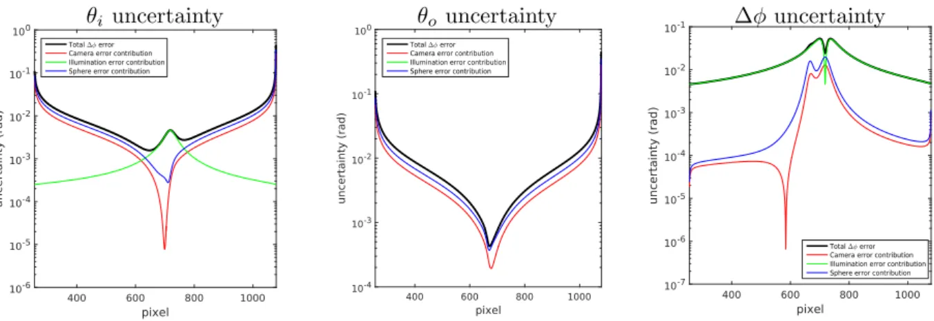
Figure 5: Uncertainty values for the BRDF angles (θi,θo,∆φ) when φstage= 7◦.
shot noise as well as other sources such as the square of the focal length, the cosine factor cos θithe vignetting effect (or
fall-off) (cosθo)4. For our setup the fall-off factor is very low
since its maximum value is 0.9957 at the silhouette of the
sphere (compared to 1.0 at the center). Figures5presents
the uncertainties values related to the geometrical calibra-tion. As one could expect, geometrical calibrated values be-come less and less reliable (up to 4 order of magnitude) when approaching grazing angle. The full analytical formula that relates every setup parameter to the BRDF value is in real-ity more complex and, particularly, non-invertible. For this reason, we have to use an algorithm that gives an approxi-mate result of the measurement, in our case (equation5), the zero-order approximation.
4. Measurements Results
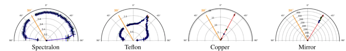
Figure6presents the BRDF measurements in the incident
plane with uncertainties for the different material samples.
Figure7shows the measured values of BRDF for Teflon
ma-terial in 2D polar plot. Overall, the error on the BRDF values
varies from 3% at normal incidence to 5% at 50◦and reaches
30% at 85◦
5. Discussion
The presented measurements with their uncertainties are pri-marily valid for our precise setup. Because of the complex interrelations among uncertainties of various parameters per-taining to such measurements, some general conclusions can be hard to find, nevertheless some hints can be deduced from
Spectralon Teflon Copper Mirror Figure 6: Incident plane BRDF measurements with uncertainty bars for the four materials.
30° 60° 90° 0° -45° -90° -135° 180° 135° 90° 45°
Teflon
Figure 7: BRDF values for the Teflon material forθi= 30◦
that arise when measuring physical quantities with imaging system.
Diffraction from the Camera Aperture An important op-tical factor that needs proper attention in a camera-based BRDF acquisition setup, and is often overlooked, is diffrac-tion originating from the aperture of the camera. The more stopped-down is the aperture the more diffraction will arise. Since we use a well stopped down aperture (f/8) in the cam-era lens and with good reason the effect cannot be neglected. Although opening the aperture would practically eliminate problems caused by diffraction, it is not a good idea, because then lens aberrations would quickly become dominant and depth of field (which is needed for spherical samples) would also reduce, causing inaccuracies of an other nature that are actually more difficult to handle. The main effects of diffrac-tion on the accuracy of obtained BRDF values are twofold (although in reality they arise from the same, single physi-cal effect causing a convolution in the image). Firstly, there is a general blurring effect that can be modeled by taking into account the first order of a circular Airy disk pattern as
convolution kernel. The second effect, is the so-called star-burst effect on highlights, the cause of which is that light gets diffracted through the aperture (hexagonal blades in our setup). In our experience the general blurring effect in our setup is negligible compared to other convolution-type ef-fects (depth of field confusion, imperfect collimation of the light source, and surface roughness), and that is for this rea-son that we set the aperture to a large value (f/8). However, the star-burst pattern around highlights is very much appar-ent and practically unavoidable. This forces us to drastically reduce the time of exposure range of the HDR imaging, and consequently the dynamic range of the BRDF measurement. In reality, the sharper the highlights on the material surface the stronger this effect. Thus, in the worst-case scenario of BRDF with a very specular component, we can only reach a 20× factor between the shortest and the longest time of ex-posure. The more diffuse the material, the higher this factor, so that this restriction is eased. In this work, we have not ad-dressed this problem yet and we simply stop recording data when the effect arises.
Diffraction White Light Speckle Another last effect of the
diffraction is due to the surface roughness, it is generally
known as the white light speckle [McK76]. It arises from the fact that on a small enough surface the light becomes coher-ent and produces grating-like light pattern when bouncing off a rough surface. If the surface is smooth or rough enough,
this effect disappears but in between it becomes prominent.
For incident light angles up to 60◦, the main effect is chang-ing locally color of the reflected light, and for more grazchang-ing angles, it also introduces a shift in the reflection angles (sim-ilarly to the effect of a grating). It then falsifies the material spatial uniformity and introduces a structured color noise. A major consequence is that, in reality, this coherence dis-appears with the divergence of the incoming light (as is the case in usual daily life when observing a scene), so using BRDF data from such a measurement introduces a percep-tion bias, which can be inconvenient for a rendering purpose. Out-of focus effect of common lenses One common issue with lenses is their lack of large depth of field, which in-troduces an error when measuring the BRDF with an imag-ing system. Indeed, one pixel of the CCD sensor recovers an irradiance value that is the convolution of the
illumina-tion with a porillumina-tion (and not only a single point pS) of the
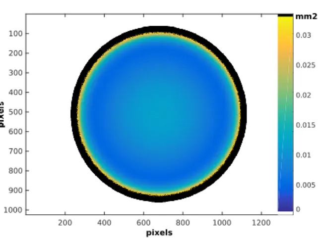
R. Hegedus& A. Lucat & J. Redon & R. Pacanowski / Isotropic BRDF Measurements with Quantified Uncertainties 200 400 600 800 1000 1200 100 200 300 400 500 600 700 800 900 1000 0 0.005 0.01 0.015 0.02 0.025 0.03 mm2 pixels
Figure 8: Illustration of the out-of-focus effect when
imag-ing a sphere. The picture shows for each pixel of the ac-quired image how much the optical rays from the lens cam-era cover the target sphere. The larger this spread the larger the error on the BRDF measurement. The spread is minimal only for the part of the target sphere which is at perfect fo-cus. For our setup, the sphere radius is 6cm and the focus is made at 4.2cm from the sphere center (corresponding to
an in-focus plane at45◦latitude). The black area starts at
θo= 68◦and finishes atθo= 85◦where the maximum area
is about2.1mm2.
task that we did not take into account in this paper. However, we simulated precisely how large the different areas on the sphere are, across which the convolution applies. As shown
in Figure8the area size ranges from 0.001mm2(part of the
sphere which are in focus) to 2.1mm2(grazing angles). Note
that we set the focus distance at 45◦latitude as a
compro-mise.
6. Future Work
As future work we would like to improve our uncertainty model by taking into account the potential (spatial and di-rectional) non-uniformity of the light source, or the lens and
also remove on-the-fly pixels where the aperture diffraction
appears. Furthermore, we would also like to average tem-porally our measurements to avoid white light speckle ef-fects.We would also like to take into account correlation
be-tween the different uncertainties by computing numerically
the co-variance matrix of the different factors. Furthermore, we would also like to study how the different BRDF models approximate these data with respect to the uncertainties pro-vided. Finally, we will also provide additional measurements for other materials to improve our qualified database.
7. Acknowledgments
R. Hegedus is grateful to the Alexander von Humboldt Foun-dation, and acknowledges their support for his fellowship for experienced researchers.
References
[BCP∗15] Belcour L., Courtes L., Pacanowski R., et al.: ALTA: A BRDF Analysis Library. http://alta.gforge.inria.fr/, 2013-2015. 3
[Bou] Bouguet J.-Y.: Camera calibration toolbox. URL:http: //www.vision.caltech.edu/bouguetj/calib_doc/.2 [DvGNK99] Dana K. J., van Ginneken B., Nayar S. K.,
Koen-derink J. J.: Reflectance and texture of real-world surfaces. ACM Trans. Graph. 18, 1 (Jan. 1999), 1–34.1
[LBAD∗06]
Lawrence J., Ben-Artzi A., DeCoro C., Matusik W., Pfister H., Ramamoorthi R., Rusinkiewicz S.: Inverse shade trees for non-parametric material representation and editing. In Proc. ACM SIGGRAPH ’06(2006), pp. 735–745.1
[Mar98] Marschner S. R.: Inverse rendering for computer graph-ics. PhD thesis, 1998.1
[McA02] McAllister D.: A generalized Representation of Sur-face Appearance. PhD thesis, University of North Carolina at Chapel Hill, 2002.1
[McK76] McKechnie T. S.: Image-plane speckle in partially coherent illumination. Optical and Quantum Electronics 8, 1 (1976), 61–67.5
[MPBM03] Matusik W., Pfister H., Brand M., McMillan L.: Ef-ficient isotropic BRDF measurement. In Proc. EGWR ’03 (2003), pp. 241–247.1
[NDM05] Ngan A., Durand F., Matusik W.: Experimental anal-ysis of BRDF models. In Proc. EGSR ’05 (2005), pp. 117–226. 1
[NRH∗77]
Nicodemus F., Richmond J., Hsia J., Ginsberg I., Limperis T.: Geometrical Considerations and Nomenclature for Reflectance. 1977.2
[RWS∗11]
Ren P., Wang J., Snyder J., Tong X., Guo B.: Pocket reflectometry. ACM Trans. Graph. 30, 4 (July 2011), 45:1–45:10. 1