Publisher’s version / Version de l'éditeur:
Vous avez des questions? Nous pouvons vous aider. Pour communiquer directement avec un auteur, consultez la première page de la revue dans laquelle son article a été publié afin de trouver ses coordonnées. Si vous n’arrivez pas à les repérer, communiquez avec nous à [email protected].
Questions? Contact the NRC Publications Archive team at
[email protected]. If you wish to email the authors directly, please see the first page of the publication for their contact information.
https://publications-cnrc.canada.ca/fra/droits
L’accès à ce site Web et l’utilisation de son contenu sont assujettis aux conditions présentées dans le site LISEZ CES CONDITIONS ATTENTIVEMENT AVANT D’UTILISER CE SITE WEB.
Technical Note (National Research Council of Canada. Division of Building
Research), 1973-01-01
READ THESE TERMS AND CONDITIONS CAREFULLY BEFORE USING THIS WEBSITE.
https://nrc-publications.canada.ca/eng/copyright
NRC Publications Archive Record / Notice des Archives des publications du CNRC :
https://nrc-publications.canada.ca/eng/view/object/?id=f2005fff-cee5-49c0-b320-70239fdc912c https://publications-cnrc.canada.ca/fra/voir/objet/?id=f2005fff-cee5-49c0-b320-70239fdc912c
NRC Publications Archive
Archives des publications du CNRC
This publication could be one of several versions: author’s original, accepted manuscript or the publisher’s version. / La version de cette publication peut être l’une des suivantes : la version prépublication de l’auteur, la version acceptée du manuscrit ou la version de l’éditeur.
For the publisher’s version, please access the DOI link below./ Pour consulter la version de l’éditeur, utilisez le lien DOI ci-dessous.
https://doi.org/10.4224/40001199
Access and use of this website and the material on it are subject to the Terms and Conditions set forth at
Vibration characteristics of a dance floor
'-:
•
,
NATIONAL RESEARCH COUNCIL OF CANADA
DIVISION OF BUILDING RESEARCH
'f
E
C
1HI
Ii ][
CAlL
T
No.
576
PREPARED BY J. H. Rainer and
D. E. Allen
CHECKED BY T. D. N. APPROVED BY A.G.W.
セ July 1973
PREPARED FOR Record Purposes
SUBJECT VIBRATION CHARACTERISTICS OF A DANCE FLOOR
Disturbing vibration amplitudes were reported on a dance floor at the La Verendrye Club, St. Boniface, Manitoba, during certain dances. In this case all applicable existing criteria in the National Building Code had been followed and yet the final performance was unsatisfactory. It was decided, therefore, to take measurements to determine the floor properties and to discuss the nature of the complaints with those associated with the design and construction of the building as well as with participants in some of the ,dances. It is anticipated that further measurements may be taken after remedial stiffening actions have been taken.
The information obtained from this case history should prove useful in arr lving at improved vibration criteria in de sign; there is no existing criterion for dance floors and the Code criterion for other floors, a defle ction limitation, has proved unsatisfactory in some case s.
DESCRIPTION OF THE BUILDING AND FLOOR
The two-storey masonry building is founded on layers of silty clay having a depth of about 50 ft. The basement contains a bowling alley, the main floor is a cocktail lounge with a small dance floor, and the second storey is a dance hall. A plan view of the floor layouts is
shown in Figures l(a) and (b). Both the ground floor and second floor consist of 3Z-in. deep open web steel joists at Z ft 6 in. o. c., with a Z liZ-in. wire mesh reinforced concrete slab, designed for non-composite action, spanning in the 48 ft direction.
2
-DESCRIPTION OF COMPLAINTS
It was reported that when certain types of dances were performed, such as a polka, the dance hall floor started to vibrate excessively. The people sitting near the dance area began to :leave as they became uncom-fortable. The liquid in glasses on tables moved noticeably. The floor vibration was reported to be particularly noticeable and unpleasant for people walking near the dance area. To エィセ person walking it became disturbing to put the foot down as the floor vibration reachecl a peak or a trough, resulting in a sensation of stepping onto a raised portion or a depression, respectively. Another effect that was observed was a "snaking" effect -- i. e. an appearance of wave motion in the long direction of the dance floor. This was made particularly visible by the reflection of the ceiling lights on the smooth linoleum. tile -covered floor.
Whenever the top floor below also started to vibrate. lounge patrons.
vibrated, the floor in the cocktail lounge This caused apprehension among the
EXPERllv1ENTAL PROCEDURE
Vibration tests were performed on the first and second floors on 24 January 1973. "Larson" accelerometers were located as shown in Figures 2(a) and (b), designated by the letters aセ Band C, and the resulting signals, filtered to eliminate frequencies above 6 to 9 Hz,
were recorded on a 2-channel "Century GP":460" galvanometer recorder. The excitation consisted of jum.ping 18 inches from a chair at the various locations shown in Figure 2 by the small circles. Another test was to
set the floor in vibration by bouncing up and down in synchronism with the natural frequency of the floor or at one half that frequency.
RESULTS
(a) Experimental
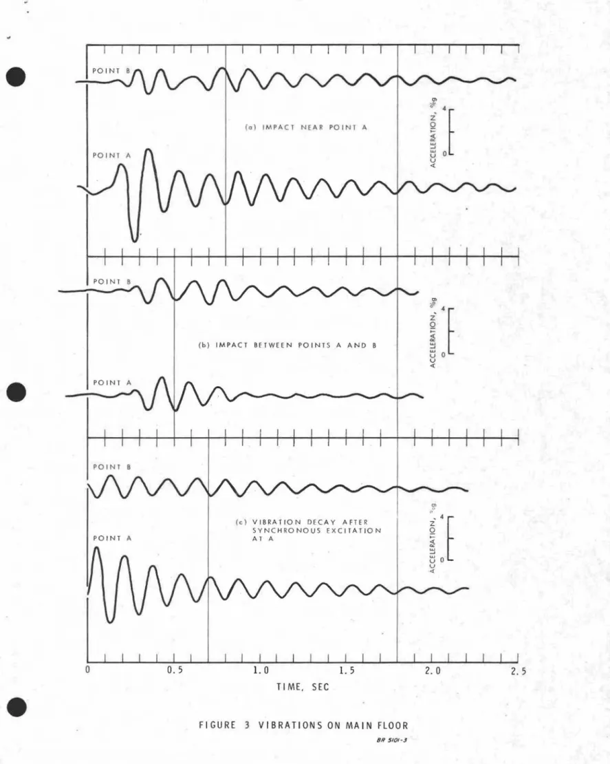
Some of the resultant records are shown in Figures 3 and 4. Observations of natural frequency and damping are summarized
in Table 1. The natural frequency was deduced from the decaying free. vibration portion of the records and the damping was computed from the decay rate, using the relation
3 -where xl and x
n are vibration aJIlplitude s
Ii-
number of cycle s apart mthe decaying portion of the vibration record.
During a steady state excitation test, the aJIlplitudes of vibration at points A and C in the second floor were found to be in the ratio of 13.5 to 1.0, indicating substantially rigid steel beaJIl support.
(b) Calculation of Natural Frequency
The fundaJIlental frequency of a uniformly-loaded simply-supported joist is given by n o 2 2 = n EIg 4wL4
where L is the span, w the we ight per unit length, g the acceleration due to gravity, I the moment of inertia, and E the modulus of elasticity. With a span of 48 ft,
n =
JI.
)29XI06
x!X386.4 = 0.501 / 1
o 2 wX(576)4 , W
where the units are pounds, inches and seconds. The dead weight of
the floor is calculated to be 46 psf, and an<:>ther 4 psf is added for
people and furniture. The IIloment of inertia of the joist (32 in. total
depth, flange areas 1. 5 in. 2, spacing 30 in.) is calculated to be 720 in. 4; for composite action with the concrete deck, the moment of
inertia is 1390 in. 4,( 2 liZ-in. concrete, 30-in. joist spacing, E c taken
as 3500 ksi). The resulting frequencies are given in Table 1.
DISCUSSION OF RESULTS
From Table I it can be seen that the computed natural frequency based on the assumption of composite action between concrete slab and
the joist is in close agreement with the measured frequencies. The
reason for the lower measured second floor frequency may be due to the presence of two air duct holes through the joist members in the second floor whereas the main floor has only one at mid-span, at
which point panel deformation due to shear is small. Also the slight
additional flexibility in the centre portion of the second floor from the
WF beaJIl support may contribute to a lowering of the frequency. It
is also possible that due to the large vibration aJIlplitudes to which the second floor has been subjected there is now somewhat less composite action than in the first floor.
4
-The second floor vibration records are somewhat irregular
in nature and it was difficult to estimate a precise frequency and damping
coefficient. This irregularity is discussed later.
The damping values obtained from the paper records presented
in Table I are seen to be in the neighbourhood of 2. 5 per cent of critical.
This is rather low when compared with those measured in other floors(1)
that were found to be in the range 3 to lO per cent of critical. Increasing
the damping is one means of reducing the vibrations.
An examination of Figures 3(a) and (c) and 4(b) shows that points-A and B vibrate out of phase when the excitation occurs near points-A, or B,
or at point D. On the other hand, when the excitation was about halfway
between A and B, the two points vibrated initially in phase as is shown
in Figures 3(b) and 4(a) but later went out of phase. The whole floor,
therefore, does not vibrate in phase but tends to form a series of rectangular panels with adjacent panels moving in opposite directions. This corroborates the observations of a snaiking action along the length of the room as previously mentioned.
The presence of these nodal lines separating the panels means that stiffening of the floor only parallel to the existing joists would do
little to alleviate the vibration problem. Load transfer perpendicular
to the existing joists, in addition to stiffening parallel to the joists, is a necessary part of remedial action.
Disturbing vibrations were experienced on the main floor when large vibrations occurred on the second floor because both floors
have almost the same resonance frequency. The small vibration
amplitudes transmitted through the partitions and the entire building at a particular frequency will induce large vibrations in any lightly
damped vibrating system having that same resonance frequency. One
way of preventing this is to avoid having identical floor systems (i. e., same configuration, stiffness and mass), although economic considerations generally favour such repetition.
For this dance floor, vibrations caused by "bouncing" or dancing in synchronism with the fundamental frequency (on every cycle or on every second or third cycle) result in large steady vibra-tions (Figure 4(b)), whereas transient vibravibra-tions caused by foot
impact are smaller (Figure 4(a)). Lenzen's criterion(2,3) is based on
transient vibrations due to foot iInpact and is, therefore, not directly
applicable to resonance problems of this type. Another proposed
5
-MEASUREMENT OF FLOOR VIBRATIONS DURING DANCES
Measurements of floor vibrations were taken on 16 and 17 February at the locations designated by 1, 2 and 3 in Figure 2(b). The accelero-meters were mounted on the floor between the end legs of the folding tables, with a cardboard cover taped over them for protection against accidential kicks. The leads were carried Underneath the table top towards the back wall and along the floor boards into the kitchen where the "Kron-Hite" filter and "Century" GP 420 recorder were located. The filter was set at
9
Hz except where noted. IAlthough the persons sitting immedifltely adjacent to a transducer were told of the instrumentation and recording setup, no general . announcement was made. During the course of the evening many people becarrle aware of 'the leads and the instrumentation, and they accepted the operation with good humour and in a cooperative. manner.
The records obtained are presented in Figures 5 to 23 in
photographic reproductions taken directly from the recorder paper. On every Figure each trace is identified by a circled number, I, 2 or 3, corresponding to the transducer location 1, 2 or 3 in Figure 2(b). The code number in the lower left corner refers to the date and serial number of the photographs taken.
Tables II and III identify and describe the tests shown in Figures 5 to 23, and summarize the results. The results for the dance on 16 February are contained in Table II and those for the dance on 17 February in Table III.
On 16 February the clientele consisted of approximately 100 persons with a large percentage of middle -aged and! older persons. The music
played by the band could be described loosely as "swinging western country style". The party might generally be de scribed as "quiet".
The inhabitants of the hall on 17 February were part of a wedding party of about 270 persons, with an age group distributed fairly uniformly from children to persons in their fifties. The music was supplied from phonograph recordings. After a somewhat quiet beginning, the party developed a lively spirit; there were generally from 50 to 100 persons on the dance floor. The capacity of the hali is limited to 300 persons, because of fire regulations.
DISCUSSION OF RESULTS OF DANCE VIBRATION MEASUREMENTS The vibration levels recorded at the 1/3 point of the joist span are grouped into three broad categories and the associated peak accelera-tions were:
6
-(a) walking, up to approxixnately 0.01 g (b) "quiet" dances (waltz), 0.01 to 0.03 g
(c) rock and roll, polka, schottische, 0.03 to 0.05 g
Figure s 18 and 19 show large anlplitude accelerations which occur at frequencies approxixnately l/Z the resonance frequency of 6 Hz of the steel-joist floor systeITl. The dance recorded on Figure ZO induced vibrations at 5 Hz which is again close to the re sonance frequency. A sixnilar steady state effect at every second natural period can be
observed in Figures 14(a), (b), and (c), the vibrations induced by a schottische.
Figure s 12 and 20 show a cOITlparison of a channel filtered at 9 and 109 Hz. In both cases the filtered signal closely reseITlbles the unfiltered one, which indicate s that the basic phenoITlenon can be adequately described by ITleans of the fundanlental mode only. Although isolated acceleration peaks in the unfiltered signal are about 50 per cent higher than the filtered one, their frequency is in the neighbourhood of
50 to 100 Hz and are likely caused by small impact disturbances near the transducer. In any case, these high frequency vibration components are not annoying.
With reference to perception criteria given in Figure 44. ZO of Ref. 5, the walking vibrations of 0.005 g are at the threshold of per-ception, whereas the 0.05 g re suIting from. Isome of the dance s is in the "unpleasant" range. The writers confirm this latter level as be ing definitely unpleasant.
Additional results presented in Ref.: 5 on response measureITlents of the human body indicate that a re sonance condition exists under
vertical excitations in the range from 3 to 6 Hz. Consequently, the human body would be expected to be particularly sensitive to vibrations
in that frequency band. Subjective nieasureITlents, such as those in Figure 44.20 of Ref. 5, confirm this extra sensitivity by showing a dip in the rating curves in the vicinity of 5 Hz.
COMMENTS ON A POSSIBLE REMEDIAL SOLUTION
i
The addition of stiffening trusses and support ITleITlbers norITlal to the trusses to provide approxiITlately double the existing floor stiffness
should achieve the following effects:
(a) the resonance frequency will be raised froITl about 6Hz to approxixnately 8 Hz, thus removing the disturbance s froITl the most sensitive range of human perception that
7
-exists at 5 to 6 Hz. It will also be more difficult to create syITlpathetic vibration due to dancing foot impact on every second cycle of the natural vibration;
(b) the amplitudes of vibration should be reduced by approxi-mately 1/2, in accordance with the increased stiffness; (c) since the floor will have joists that have different
resonance frequencies, the uniform bouncing of the' entire floor will be prevented; and
(d) since the second-floor dance surface will have a substantially different natural frequency from the main floor, the
occurrence of syITlpathetic resonance effects in the cocktail lounge will be reduced.
The proposed remedial action thus should result in vibration levels dliring dancing that are well below the "unpleasant" category. REFERENCES
1. Full Scale Testing of New York World's Fair Structures. Vol. 1, the Bourbon Street Structures, B.R.A.!? ,National Academy of Sciences (U. S. ), Publication 1720, 1969.
2. Lenzen, K. H. Final Report, Vibration of Steel Joist - Concrete Slab Floor Systems. Studies in Engineering Mechanics, Report No. 16, Univ. of Kansas, 1963.
3. Lenzen, K. H. Vibration of Steel Joist - Concrete Slab Floors. A. 1. S. C. Engineering Journal, July 1966.
4. Funk, P. Stiffness Requirements in Terms of Human Comfort. Discussion No. I, Technical Committee No. 24, Stiffness and Crack Control, Vol. DS, A.S.C.E. -- LA.B.S.E. International Conference Preprints, Planning and Design Of Tall Buildings, Lehigh University, August 21-26, 1972.
5. Harris, C .M. and Crede, C. E. Shock and Vibration Handbook, Vol. 3, Chapter 44.
ACKNOWLEDGEMENTS
This investigation arose from an inquiry to the Technical Infonnation Service (T. 1. S.) of the National Research Council of Canada in Winnipeg, Manitoba. The writers are indebted toMr. T. Jensen of T.1.S.,
-.
8
-and installation of the transducers. The cooperation of the following is also gratefully acknowledged: Mr. D. L. Lussier, Gaboury Lussier Sigurdson, Architects, St. Boniface; Mr. Gil Belanger, Manager, Le Club La Verendrye, St. Boniface; and Professor G. Morris, Departm.ent of Civil Engineering, University of Man.itoba.
•
•
TABLE I. Dynamic Characteristics of Floor
Natural Frequency (Hz) calculated
measured composite non-composite
Damping Coefficient 8,
%
of critical Main Floor Second Floor 6.0 5.3 - 6.05.86
4.18 2. 5 - 3.0 2.0-3.5e
Figure
No. Caption
TABLE
n.
Dance on it) e r u a r y 1973Maxirnum Peak Acc elera tions, g
Channel
I
gI
c:
(lannel I g Remarks•
.
.
•
5 6 7 a.) 7 b. ) 8 9 10 11 12 13 14 a. ) 14 b. ) 14 c. )Person walking 1engthv,ise near middle of hall
Person walking lengthwise near middle of hall
2 men walking in step
2 men walking in step (continued) 2 men followed by 2 women
walking
2 men walking independently behind one another
"Quiet" period, no one walking; about 100 persons sitting at tables One- step polka, approximately 20 couples
9 Hz and 109 Hz filtered signal, slow music
l'Old time" one-step
Schottische, approx. 30 couples
Schottische, approx. 30 couples (c ontinued)
Schottische, approx. 3
a
couples (c ontinued) 1 1 1 1 1 2 2 2 2 1 1 2 2 O. 003 0.004 0.006 0.004 0.004 0.008 0.002 0.017 0.006 (9 Hz) 0.012 0.024 0.037 O. 036 2 2 2 2 2 3 3 3 2 2 2 3 3 O. G02 0.002 0.U05 0.003 0.005 0.009 0.002 0.ul5 0.008 (109 Hz) 0.018 0.036 0.024 0.021 Out of phaseMostly out of phas e
Mostly in phase Mostly out of phase No clear correlation
Not well correlated
Out of phase
Mostly in phase, approx. 5 Hz
Mostly in phase,
irr egular and about 5 Hz Mostly in phase, about
3. 5 Hz on 2, 6 Hz on 1. Not well corr elated, 3. 5 Hz on 2, 6 Hz on 3
Slightly out of phase, about 3.5 Hz response on 2, 6. 5 Hz on 3 15
16
"Old time" waltz
Heel impact near location 1
1 1
o.
nos
O. 022 2 2 0.008 0.008 No clear correlation Initially out of phase, then in phaseHセ
r
([
セ .. 17I
Figure No. 10 "Quiet" period, no one walking; about 100 persons sitting at tables. (Timing m.arks at 0.1 sec.)
Figure No. 11 One-step polka, approximately 20 couples. (Timing m.arks at 1.0 sec.)
Figure No. 129Hz and 109 Hz filtered signal, slow tnusic. (Titning tnarks at 1.0 sec.)
Figure No. 13 "Old titne one -step". (Titning tnarks at 1. 0 sec.)
1'.2.-11
Figure No. l4(a) Schottische, approx. 30 couples. (Timing marks at 1.0 sec.)
1'.2. /2
Figure No. l4(b) Schottische. approx.
30
couples (continued). (Timing marks atFigure l4(c) Schottische, approx. 30 couples
(continued). (Timing marks at 1.0 sec.)
Figure No. 15 "Old time waltztt• (Timing marks at
/
\
j IV lr-r-.-iI'i'..'" セr
',J""
\ \, \I \.>/'""
.. /4Figure No. 16 Heel impact near location 1. (Timing
marks at O. 1 sec.)
17.2-1
Figure No. 17 Polka, about 10 couples. (Timing
•
e
TABLE III. Dance on 17 February 1973
e
Maximum Peak Accelerations, g Figure No. 17 18 a. ) 18 b. ) 19 a. ) 19 b. ) 20 21 22 23 Caption
Polka, about 10 couples
"Rock around the clock", 30-40 couples
"Rock around the clock", 30-40 couples (continued)
Rock and roll music
Rock and roll music (continued)
Heavy rock and roll,
9 Hz and 109 Hz filtered
Viennese waltz, about 15 couples "B utterfl y" waltz (slow and
fast, alternating), about 40 couples
Rock and roll
Channel 1 1 2 2 1 2 1 1 1 g 0.008 0.03 0.034 0.03 0.022 0.034 (9 Hz) 0.005 0.024 0.028 Channel 2 2 3 3 2 2 2 2 2 g 0.015 G.05 0.019 0.015 0.03 0.050 (109 Hz) 0.008 0.027 0.04 Re.marks No clear correlation or dominant frequency In phase, about 3.5 Hz 3.5 Hz on 2 6.5 Hz on 3 3.2 Hz on 2 6.2 Hz on 3, approx.
Not well correlated 3.2 and 6.2 Hz on 1, 3.2 Hz on 2;
Mostly in phase
About 5.5 Hz;
Not well correlated About 3. 5 Hz;
L
ENTRANCE セj
1 2" CON C RET E WALLS BELOW, BASEMENT ALL AROUND INTERIOR STUDWALL AND PLASTER
PARTITIONS -o I
I
iセ
CONCRETE BLOCKAND BRICK MASONRY
109' -4"
1-0.... . . - - - . EX TE RIO R WA LL.S
FIGURE l(al MAIN FLOOR LAYOUT
PIPE COLUMN BELOW
EXTERIOR CONCRETE
BLOCK AND BRICK
MASONRY WALL .'>--flf--_INTERIOR STUD WALL PARTITIONS
/24
'IF 100 BELOW( ---' '---I
\ I _ - - I DANCE AREA)I
I I II II
I \セ
--=-
--=-=-- --
- - - - ' : SEATING AREAl
L__
:
8" 'IF COLUMNSFIGURE UbI SECON 0 FLOOR LAYOUT
L
FIGURE
2(a)
LO CAT ION: 0 F TRAN S DUCERS (A, B) AND
IMPACT POINTS (1-4) ON MAIN FLOOR
KITCHEN
FIGURE
2(b)
LOCATION OF TRANSDUCERS (A, S, C) AND
(1,2,3) AND IMPACT POINTS
(0)ON SECOND
FLOO R
( D \ IMP ACT N A R PO I N T A
PO I NT A
(b) IMPACT BETWEEN POINTS A AND B
en セ Z 4
t
Q セ LU ...J LU U 0 U <{ PO I N T 8leI VIBRATION DECAY AFTER
SYNCHRONOUS EXCITATION AT A '5'
f[
UO[
u <{o
2.5 TI ME, SECFIGURE 3 VIBRATIONS ON MAIN FLOOR
o
(0) IMPACT BETWEEN POINTS A AND B
en /' セ Z
t
Q I of ... W u:: 0 u U <i. 10 [ z· Qi
o TIME, SECFIGURE 4 VIBRATIONS ON SECOND FLOOR
I
'\ \1/ \ / .11\ \ "-
",y
/"I'" f\./I\. \1/"- ...:v
セ
C
t
I(? 1\ Ir .... .... ...11' "-Vb-Figure No. 5 Person walking lengthwise near middle
of hall. (Timing marks at O. I sec.)
I -1\il\. J r\ I\. J \1/ \ f\.V h/1\1/
rv,\/r--
v\['
- .. . -2. v\ \11' il- I,. セ -f-" セ-Figure No. 6 Person walking lengthwise near middle
I Ir
( 1/
1 \ 1/ I" It, '"'"
"
1\ II' h セ IV IJ セ f\1\
セ lJ セr
I:z セ , セ,
[\ I\vvr\
1\
lIt--f\ 1/1\ "" セNh
1\ tJ IJ LI1\
Nセ t ..-Figure No. 7(a) Two men walking in step. (Timing
marks at O. I sec.)
セ
セ V' セセ V/1\IJ'IIIJII\l1I11I11 vセO
v
1\ h t"r'I1/ " ' ' ' ' ' ' " '1\ 1\ V II
I--セ .. H 1\ 1\
Figure No. 7(b) Two men walking in step (continued).
•
•
-
-
.--I
-IJ1\.1I 1\セ ""hセi|ij 1\ セ
rY
V
セ イNNセ f,l1\lifo' tijI'" セ セ V
I':
0, セ
セd
I.r !/I\1/1\1/1\1/1\11 セ iOセ f-It\1.11\ャOセ II rv'iV""V'rvh
セN .
Figure No.8 Two men followed by two women walking.
(Timing marks at 0.1 sec.)
j
b
ao,
Figure No.9 Two men walking independently behind one
(j)
Figure No. l8(a) "Rock around the clock", 30 - 40 couples. (TiIning marks at 1. 0 sec.)
17.2.-3
Figure No. l8(b) "Rock around the clock", 30 - 40 couples (continued). (TiIning marks at 1.0 sec.)
17.2.-4
Figure No. 19(a) Rock and roll music. (Timing
marks at 1.0 sec.)
OJ
1'1'
II
AJ\セ
\, 1'1\1 Ii \ V セvセ
{\ IV
セA
-5Figure No. 19(b) Rock and roll music (continued).
QWNRNセHL
Figure No. 20 Heavy roc\t and roll, 9 Hz and 109 Hz filtered. (Timing marks at I. 0 sec.)
Figure No. 21 Viennese waltz, about 15 couples. (Timing marks at 1.0 sec.)
,
..
•
'\r/\.hGセG|
r
セGB
i\,
!\;'\
:\1
I -\ V 'I i ' I \ ,.
,.
: 1,1'" I ,1,1 '" L'" 01.,\ I ' '1 tl I , ' I : ' · I l"",I, "!' I, '.I,' , • " セ•
'. /7.2..-8Figure No. 22 UButterfly waltz" (slow and fast,
alternating), about 40 couples. (Timing marks at 1.0 sec.)