HAL Id: hal-02178781
https://hal.archives-ouvertes.fr/hal-02178781
Submitted on 12 Mar 2020HAL is a multi-disciplinary open access archive for the deposit and dissemination of sci-entific research documents, whether they are pub-lished or not. The documents may come from teaching and research institutions in France or abroad, or from public or private research centers.
L’archive ouverte pluridisciplinaire HAL, est destinée au dépôt et à la diffusion de documents scientifiques de niveau recherche, publiés ou non, émanant des établissements d’enseignement et de recherche français ou étrangers, des laboratoires publics ou privés.
Effect of natural and anthropogenic soil heterogeneities
on the liquefaction-induced damage of a levee
Christina Khalil, Fernando Lopez-caballero
To cite this version:
Christina Khalil, Fernando Lopez-caballero. Effect of natural and anthropogenic soil heterogeneities on the liquefaction-induced damage of a levee. 7th international conference on earthquake geotechnical engineering, Jun 2019, Roma, Italy. �hal-02178781�
Effect of natural and anthropogenic soil heterogeneities on the
liquefaction-induced damage of a levee
C. Khalil
Laboratoire MSS-Mat CNRS UMR 8579, CentraleSup´elec Paris-Saclay University, France
F. Lopez-Caballero
Laboratoire MSS-Mat CNRS UMR 8579, CentraleSup´elec Paris-Saclay University, France
ABSTRACT: In the performance-based earthquake engineering, the wide range of uncertainties is taken into account explicitly through probabilistic evaluations of liquefaction susceptibility, triggering, and consequences. Liquefaction is one of the most devastating and complex behaviors that affect the soil. It usually happens due to strong shakings. Recent studies have been conducted in order to characterize and strengthen the soil. These improvement techniques, among others, induce an amelioration in the behavior of the soil. The aim of this paper is to design numerical tests that take into consideration the soil-structure effect under controlled conditions, quantify the damage of the structure and check the effect of the soil heterogeneity on the behavior of the soil subjected to real earthquakes. Heterogeneity in this paper is referred to the soil treated with injected material. For this purpose, a 2D finite element model of an embankment founded on a layered soil/rock profile is considered. An elasto-plastic multi-mechanism model is used to represent the soil behavior.
1 INTRODUCTION
In the methodology of the performance-based earthquake engineering, in addition to the hazard analysis, a deterministic and probabilistic studies must be done in order to come up with an effec-tive cost for the decision makers (Porter 2003). For the soil, things are more complicated since it has a large range of uncertainties that will affect the variability of the ground response (Popescu et al. 2005). They are either due to the variation of the soil properties, or natural processes or man-made interference.
Soil liquefaction and the resulting ground deformations cause extensive damages in the affected area. Liquefaction, as a definition, is the loss of the soil of its shear strength due to the excess of pore water pressure (Ishihara et al. 1975, Castro et al. 1982, Kramer 1996, among others). The soil particles will no longer be in contact between each other and hence unable to resist the strong sudden shaking. Considering the soil as a living ecosystem gives the potential to find several improvement techniques that requires biology and geochemistry for ground modification (Fauriel et al. 2013). The improvements consists of injecting a stiff material between the soil particles in order to strengthen it and make it more sustainable to resist liquefaction. This will modify the soil to create a heterogeneous area that will affect the ground response.
This paper aims to assess numerically the effect of the soil heterogeneity on the liquefaction-induced failure to a levee. Two cases were studied: i) a homogeneous case which designates the case of the embankment model with no treatment of the liquefied shallow layer and ii) an heterogeneous case which designates the treated soil in the liquefied shallow layer of the foun-dation. In order to account for the natural hazards, the input ground motions were chosen to be real motions and they were taken from a previous study conducted by Lopez-Caballero & Khalil (2018). Whereas to account for the heterogeneity of the soil, previous studies regarding this aspect has been conducted and they are inspired for this study (i.e. Montoya-Noguera & Lopez-Caballero (2016). In this work, an injecting material was used and will serve for improvement purposes.
The finite element calculations were performed using the GEFDyn code (Aubry et al. 1986). The quantifiable parameter to designate the induced damage on the embankment is taken to be the crest settlement. It was compared between the two cases as to validate its reduction regarding the soil improvement.
2 MODEL DESCRIPTION 2.1 Geometry and FE model
The geometry of the model, as shown in Figure 1, consists of an embankment of 9 m high com-posed of dry dense sand. The soil foundation is comcom-posed by a liquefiable loose sand of 4 m at the top of a saturated dense sand of 6 m. The bedrock at the bottom of the dense sand is 5 m and has the shear wave velocity Vs = 1000 m/s. The water table is situated at 1 m below the base of the levee that was kept dry. The levee’s inclination is a slope of 1:3 (vertical: horizontal). The geometry used in the FEM was inspired by the one proposed by Rapti et al. (2018).
As for the FE model, a 2D coupled finite element modelling with GEFDyn Code (Aubry et al.
10-6 10-5 10-4 10-3 10-2 [1] 0 0.2 0.4 0.6 0.8 1 G/G max [1] Dense LMS Seed and Idriss (1971)
100 101 102 Number of Cycles, N [1] 0 0.1 0.2 0.3 0.4
Cyclic Stress Ratio, SR [1]
Dr = 60%* Dr = 80%* * Byrne et al. (2004) Dr = 40%* p 0=50kPa Dense LMS D ense sand 9m 20m 74m W ater table B edrock L M SA N D L M SA N D D E N SE SA N D D E N SE SA N D 1m 3m 3m 3m 194m
Figure 1.: Geometry and behavior of the soil (Lopez-Caballero & Khalil 2018)
1986) is carried out using a dynamic approach derived from the u − pw version of the Biot’s
generalized consolidation theory (Zienkiewicz 1991). The FE model is composed of quadrilat-eral isoparametric elements (1 m by 0.5 m) with eight nodes for both solid displacements and fluid pressures. The FE analysis consider the homogeneous and the heterogeneous cases. It is per-formed in three consecutive steps: i) a computation of the initial in-situ stress state due to gravity loads; ii) a sequential level-by-level construction of the embankment and iii) a seismic loading analysis in the time domain. Regarding the heterogeneous case, the treated soil consists of inject-ing a new material in the loose sand layer via a probabilistic law that will be developed in section 2.2 and execute the calculations similar to an untreated case. This methodology will help to avoid the discontinuities of the model provided from the properties of two different materials. The het-erogeneity in this paper will help to understand the hethet-erogeneity caused by the soil improvement techniques.
2.2 Injection Technique
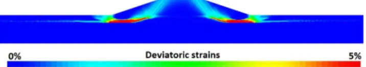
The liquefaction-susceptibility of the soil during seismic activities is enhanced by the use of vari-ous improvement techniques (Bradley et al. 2013). Normally, the techniques require the horizontal injection of stiff material that will improve the soil and make it more sustainable to liquefaction. Concerns about the spatial distribution of the injected material, its timing rate of injection as well as its depth in soil, should be made in order to make this change helpful for mitigation (DeJong et al. 2010).Therefore, based on literature, one of the failure patterns under an embankment is the one described as a zone that starts beneath the embankment and continues vertically or inclined toward the slopes. A wedge shape would be created around the crest of the embankment (Kramer 1996, Kourkoulis et al. 2010, Sadeghi et al. 2014, among others). Figure 2, extracted from a study conducted by Rapti et al. (2018), shows the distribution of the deviatoric strain at the end of the
motion. It is clear from Figure 2 thatεdis located below the toes of the levee, which confirms
the wedge shape developed in the literature. For this reason, the injection of the material might be more efficient if the treatment zone was located under the slope of the embankment (Figure 1). As for the depth of the treatment zone, it should consist of the layer that is more susceptible
Figure 2.: Deviatoric strainεdat the end of the ground motion (Rapti et al. 2018)
to liquefaction. Hence, theG/Gmax − γ curve and the cyclic resistance ratio C SR were found for the dense and loose layers of the foundation for the untreated case. The results are shown in Figure 1. It is clear that the shallow layer tends to liquefy more, hence it is the layer that should be injected.
It is known that the efficacity of the mitigation method, precisely the injected length depends on the ground porosity, geometry and depth of the treatment zone. Cruz (2014) in his work, has shown the effect of the heterogeneity of the soil porosity on the injected length, this relation fol-lows a probabilistic approach called the power law distribution (Reeves et al. 2008). At every depth in the liquified shallow layer, the material used for treatment is injected horizontally in a probabilistic way following the formula (Reeves et al. 2008):
P (L > l) = wl−a (1)
whereP = probability of the length of injection L; w = a constant that depends on the minimum length taken to be 1;l = the max length on injection and a = a power law exponent taken to be 1.5. Based on this methodology, three types of injection zones under the edge of the embankment are created and are shown in Figure 3. Despite the spatial distribution of the material, the soil
(a) type 1 (b) type 2 (c) type 3
Figure 3.: The different types of injections
behavior of the concerned layer as well as the injected material is important to be known in order to understand the global response of the embankment.
2.3 Soil Behavior
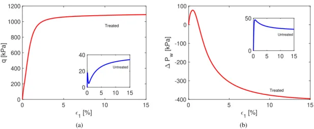
A constitutive model for soils should be able to well represent the volume change in case of drained conditions or the distribution of the excess pore water pressure in case of undrained con-ditions (Aubry et al. 1982). The use of numerical modeling best describes the non-linear soil behavior under cyclic loading. The Ecole Centrale Paris (ECP) elastoplastic multi-mechanism model (Hujeux 1985, Aubry et al. 1986) is the one used in this study in order to represent the soil behavior of the tested material of the liquefied layer of the foundation. The non-linearity of this model is represented by four coupled elementary plastic mechanism: three plane-strain deviatoric plastic strain mechanism in three orthogonal planes (k - planes) and an isotropic plane to take into account normal forces. The detailed study of this model is beyond the scope of this work. In order to understand the behavior of the foundation shallow soil and the material injected, monotonic triaxial undrained tests were simulated on each material. The nomination adopted for this study is that “Untreated” soil designates the loose sand of the shallow foundation layer and “Treated” soil designates the material injected in the same layer. The results are shown in Figure 4. The stress
0 5 10 15 1 [%] 0 200 400 600 800 1000 1200 q [kPa] Treated 0 5 10 15 0 20 40 Untreated (a) 0 5 10 15 1 [%] -400 -300 -200 -100 0 100 P w [kPa] Treated 0 5 10 15 0 50 Untreated (b) Figure 4.: The soil behavior of the treated and untreated soil
path shown in Figure 4, shows that the treated material has a dilatant behavior since the confin-ing stressq keeps increasing as function of the vertical strain. On the contrary, from Figure 4a, the untreated material has a contracting behavior. Regarding the liquefaction potential, the excess pore water pressure was drawn for the two tested soils. It can be seen from Figure 4b, that the treated soil has a tendency to resist for liquefaction, whereas the untreated soil liquefies rapidely (i.e.∆Pw reaches the value of the confining pressure). Moreover, characterizing the liquefaction
phenomena, needs the understanding of not only the behavior of the soil, but also the identification of the input motion in order to analyze the ground response.
2.4 Input Ground Motion
The selection of input motions for geotechnical earthquake engineering problems is important as it is strongly related to the nonlinear dynamic analysis. In this study, eleven different earthquakes were chosen to represent the dynamic behavior of the model. They are chosen to be real in order to represent the consistency of the seismic parameters and characteristics. They are extracted from a study conducted by Lopez-Caballero & Khalil (2018).
3 RESULTS
For dams under seismic activities, the modes of failure usually studied are the crest settlement or the internal erosion and piping failure caused by cracks in the dam (Wu 2014). In this study, the crest settlement is chosen to be the mode of failure of the embankment because it is a quantifiable measurement. First, a comparison between the values of the co-seismic crest settlement in the homogeneous (or untreated) case and when the new material was injected, was made. Second, the relative crest settlement at the end of the ground motion was analyzed for the different types of injection zones.
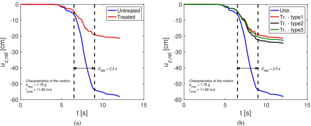
Starting by the co-seismic settlement for the case of homogeneous soil and when the different injections are applied, the results are shown in Figure 5. The negative sign of the displacementuz
in Figure 5 means that the settlement occurs in the downward direction. For the sake of brevity, one ground motion was taken as an example. Its outcrop accelerationamax,outis equal of 1.76 g
and the effective durationD595is 2.5 s (Figure 5). Notice thatD595refers to the generation of 5%
and 95% of the energy of the motion.
It can be seen from Figure 5 that the crest settlement at the beginning of the earthquake is not affected. At a certain time (i.e. around 4 seconds), it starts to decrease slightly. At the beginning of the effective durationD595, the crest settlement decreases rapidly until the generation of 95% of
the energy where it will decrease slightly. It is well evident that the response of the soil depends on the characteristics of the input ground motion. For example, based on Lopez-Caballero & Modaressi-Farahmand-Razavi (2010), the Arias intensity at outcropping Iarias,out has the best
0 5 10 15 t [s] -60 -50 -40 -30 -20 -10 0 u z,rel [cm]
Characteristics of the motion: amax = 1.76 g Iarias = 11.85 m/s D595 = 2.5 s Untreated Treated (a) 0 5 10 15 t [s] -60 -50 -40 -30 -20 -10 0 u z,rel [cm]
Characteristics of the motion: amax = 1.76 g Iarias = 11.85 m/s D595 = 2.5 s Untr. Tr. - type1 Tr. - type2 Tr. - type3 (b)
Figure 5.: Comparison of the crest settlement of the embankment a) when the model is treated and non treated and b) with the different types of injections
is not the same for all the tested ground motions and what is represented in Figure 5 is just a test case. From Figure 5a,uz,rel was reduced from 58 cm to 20 cm. This is clear that the settlement
is reduced when the soil was injected. Furthermore, the randomly chosen type of injections affect the response of the soil due to the distribution of the treated zone within the untreated soil. This variation is best represented in Figure 5b. A comparison with the case of untreated soil is shown also in this figure (blue curve). The reduction of the crest settlement at the end of the shaking is very clear in Figure 5b. In addition, the spatial distribution of the injected material plays a role in the ground response due to the slight different values of the crest settlement at the end of the shaking. Comparing Figures 3 and 5b, it can be assumed that wider the area of improvement, lesser the crest settlement (Dimitriadi et al. 2018).
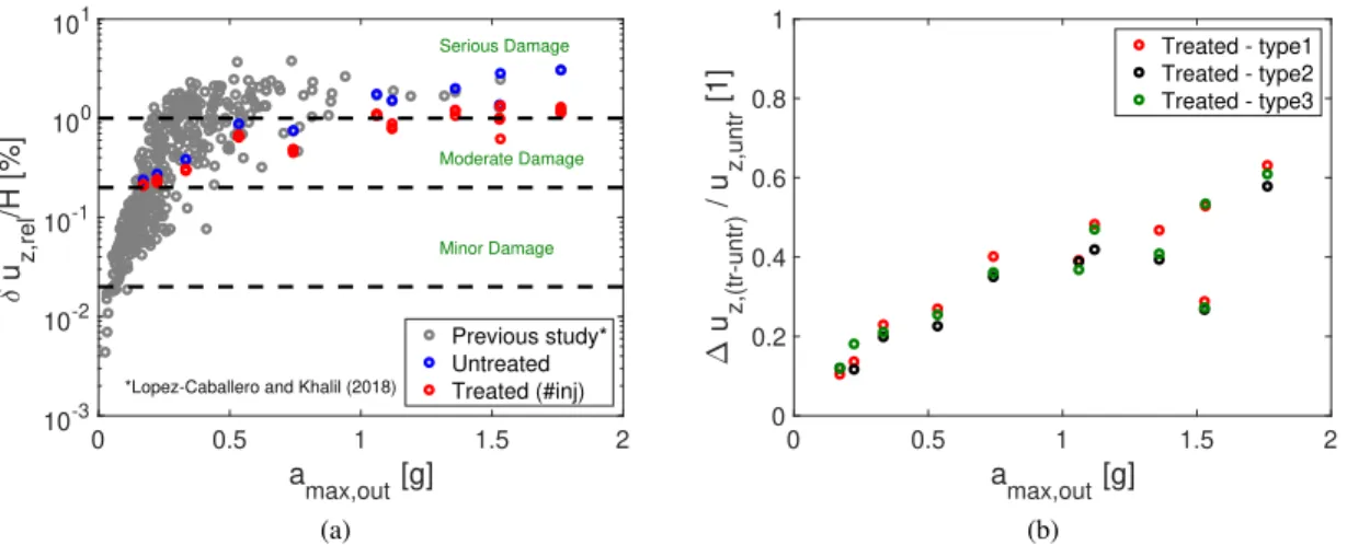
Taking into account all the tested ground motions, Swaisgood (2003) in his study, analyzes a historical database on the performance of dams during earthquakes and found that the crest settlement is directly related to some input ground motion characteristics (i.e. the peak ground acceleration and magnitude). Following Swaisgood (2003) proposition, in this work the obtained percentage crest settlement (δuz,rel/H, where uz,rel is the relative crest settlement, H is the
height of the dam and the foundation which is 19 m) is compared to the peak ground acceler-ation at the outcropping bedrock (amax,out). The results are shown in Figure 6a. The model in
the homogeneous case (i.e. blue dots) and when the three types of injections are applied (i.e. red dots) are shown in Figure 6a. Also in Figure 6a, a study conducted by Lopez-Caballero & Khalil (2018) on the same numerical model with different finite element sizes is shown with grey dots in order to represent the entire response of the soil The damage levels of the percentage crest settle-ment proposed by Swaisgood (2003) are also shown in Figure 6a. A consistency with the results (Figure 6a) between the study conducted by Lopez-Caballero & Khalil (2018) and the current one regarding the ground response; the relative crest settlement increases when the acceleration at the outcrop increases. In order to better simulate the treatment zone, the size of the element in the current study was refined compared to the previous one, hence the blue dots that designate the untreated soil serve for comparison with the treated cases. It is clear from Figure 6a that the percentage crest settlement is reduced comparing to the case when the soil was not treated. It is interesting to mention that in some cases, the crest settlement reduction transformed the damage from a “serious” level to almost a “moderate” level. Also from Figure 6b, for small values of the accelerationamax,out, the reduction in the crest settlement is not very important comparing to the
one happening at strong accelerations. This analysis emphasizes the need to ameliorate the soil in order to have better ground response regardless of the type of injections adopted.
In order to better understand the effect of the input ground motion with the engineering demand parameter, as well as the influence of the heterogeneity induced from the soil treatment, the nor-malization of the crest settlement was drawn. The results are shown in Figure 6b. It can be seen that when the acceleration increases, the normalized crest settlement increases. For example, when
0 0.5 1 1.5 2 amax,out [g] 10-3 10-2 10-1 100 101 u z,rel /H [%]
*Lopez-Caballero and Khalil (2018)
Serious Damage Moderate Damage Minor Damage Previous study* Untreated Treated (#inj) (a) 0 0.5 1 1.5 2 amax,out [g] 0 0.2 0.4 0.6 0.8 1 u z,(tr-untr) / u z,untr [1] Treated - type1 Treated - type2 Treated - type3 (b)
Figure 6.: The crest settlement analysis with respect to the outcropping acceleration (amax,out)
amax,out= 1.7g, the crest sellement reduction reaches 60%. This means that the reduction of the
crest settlement due to the treatment of the soil is efficient for strong ground motion and does not make big effects for motions of small accelerations.
4 CONCLUSION
The soil liquefaction induced settlement for an embankment dam due to real earthquakes was assessed numerically in this paper. An elastoplastic multi-mechanism soil behaviour model was used with the help of a 2D finite element code (GEFDyn). The performance-based earthquake engineering methodology was investigated by taking into account the wide range of uncertain-ties through probabilistic approaches. To quantify the damage subjected to the embankment, the induced crest settlement was chosen to be the engineering demand parameter. The effect of the soil heterogeneity was accounted for by the injection of a new material in the shallow layer of the foundation that will serve for soil improvement.
First, it should be noticed that the capability of the chosen finite element code is very powerful since it can deal with several complex scenarios and boundary conditions. The effect of the soil-structure interaction under controlled conditions was accounted for with the help of this model in addition to the heterogeneity of the soil. The heterogeneity was accounted for by a method of soil improvement that consists of injecting a stiff material that will serve to strengthen the soil. The spatial distribution of the added material was considered using a probabilistic law.
At the beginning of the study, it was shown that the injection of a new stiff material reduce the crest settlement of the embankment. In addition, the distribution of the new material has an important role; the wider the zone of injection, the better the results regarding the crest settlement. In addition, based on previous studies, the crest settlement of the embankment is linked to the acceleration of the input motions. This idea was confirmed in this study. It was also shown that in the heterogeneous case, the crest settlement generates moderate damage instead of serious damage.
Finally, the results of this study show consistency with the theory as well as the practical cases. It should clarified that the heterogeneity that comes from the soil improvement techniques is beneficial for the ground response whereas it might not play the same role if it comes from other aspects.
5 ACKNOWLEDGMENT
This work, within the ISOLATE project, benefited from French state funding managed by the National Research Agency reference under program Mobility and Sustainable Urban Systems (DS06) 2017 reference No. ANR-17-CE22-0009. The research reported in this paper has been supported in part by the SEISM Paris Saclay Research Institute.
REFERENCES
Aubry, D., Chouvet, D., Modaressi, A., & Modaressi, H. 1986. Gefdyn: Logiciel d’analyse de comportement m´ecanique des sols par ´el´ements finis avec prise en compte du couplage sol-eau-air. Manuel scientifique, Ecole Centrale Paris, LMSS-Mat.
Aubry, D., Hujeux, J., Lassoudiere, F., & Meimon, Y. 1982. A double memory model with multiple mechanisms for cyclic soil behaviour. In Proceedings of the Int. Symp. Num. Mod.
Geomech, pp. 3–13.
Bradley, B. A., Araki, K., Ishii, T., & Saitoh, K. 2013. Effect of lattice-shaped ground improve-ment geometry on seismic response of liquefiable soil deposits via 3-d seismic effective stress analysis. Soil Dynamics and Earthquake Engineering 48, 35–47.
Castro, G., Enos, J., France, J. W., & Poulos, S. 1982. Liquefaction induced by cyclic loading.
NASA STI/Recon Technical Report N 83.
Cruz, D. A. C. 2014. Research at the improvement of soil properties by calcium carbonate precipitation.
DeJong, J. T., Mortensen, B. M., Martinez, B. C., & Nelson, D. C. 2010. Bio-mediated soil improvement. Ecological Engineering 36(2), 197–210.
Dimitriadi, V. E., Bouckovalas, G. D., Chaloulos, Y. K., & Aggelis, A. S. 2018. Seismic liq-uefaction performance of strip foundations: Effect of ground improvement dimensions. Soil
Dynamics and Earthquake Engineering 106, 298–307.
Fauriel, S., Laloui, L., et al. 2013. Biogeochemical processes and geotechnical applications: progress, opportunities and challenges. Geotechnique-London- 63(ARTICLE).
Hujeux, J. 1985. Une loi de comportement pour le chargement cyclique des sols. G´enie
parasismique, 287–302.
Ishihara, K., Tatsuoka, F., & Yasuda, S. 1975. Undrained deformation and liquefaction of sand under cyclic stresses. Soils and foundations 15(1), 29–44.
Kourkoulis, R., Anastasopoulos, I., Gelagoti, F., & Gazetas, G. 2010. Interaction of foundation-structure systems with seismically precarious slopes: Numerical analysis with strain soften-ing constitutive model. Soil Dynamics and Earthquake Engineersoften-ing 30(12), 1430–1445. Kramer, S. L. 1996. Geotechnical earthquake engineering. in prentice–hall international series
in civil engineering and engineering mechanics. Prentice-Hall, New Jersey.
Lopez-Caballero, F. & Khalil, C. 2018. Vulnerability assessment for earthquake liquefaction– induced settlements of an embankment using gaussian processes. ASCE-ASME Journal of
Risk and Uncertainty in Engineering Systems, Part A: Civil Engineering 4(2), 04018010. Lopez-Caballero, F. & Modaressi-Farahmand-Razavi, A. 2010. Assessment of variability and
uncertainties effects on the seismic response of a liquefiable soil profile. Soil Dynamics and
Earthquake Engineering 30(7), 600–613.
Montoya-Noguera, S. & Lopez-Caballero, F. 2016. Numerical modeling of discrete spatial het-erogeneity in seismic risk analysis: application to treated ground soil foundation. GeoRisk:
Assessment and Management of Risk for Engineered Systems and Geohazards 10(1), 66–82. Popescu, R., Deodatis, G., & Nobahar, A. 2005. Effects of random heterogeneity of soil
properties on bearing capacity. Probabilistic Engineering Mechanics 20(4), 324–341. Porter, K. A. 2003. An overview of peer’s performance-based earthquake engineering
method-ology. In Proceedings of ninth international conference on applications of statistics and
probability in civil engineering. Citeseer.
Rapti, I., Lopez-Caballero, F., Modaressi-Farahmand-Razavi, A., Foucault, A., & Voldoire, F. 2018. Liquefaction analysis and damage evaluation of embankment-type structures. Acta
Geotechnica, 1–19.
Reeves, D. M., Benson, D. A., & Meerschaert, M. M. 2008. Transport of conservative solutes in simulated fracture networks: 1. synthetic data generation. Water resources research 44(5). Sadeghi, H., Kimoto, S., Oka, F., & Shahbodagh, B. 2014. Dynamic analysis of river
embank-ments during earthquakes using a finite deformation fe analysis method. In 14th
Interna-tional Conference of the InternaInterna-tional Association for Computer Methods and Advances in Geomechanics, Number 2011, pp. 637–642.
Swaisgood, J. 2003. Embankment dam deformations caused by earthquakes. In Pacific
confer-ence on earthquake engineering.
Zienkiewicz, C. 1991. The finite element method; solid adnd fluid mechanics. Dynamics and