HAL Id: hal-00835407
https://hal.archives-ouvertes.fr/hal-00835407
Submitted on 18 Jun 2013
HAL is a multi-disciplinary open access
archive for the deposit and dissemination of
sci-entific research documents, whether they are
pub-lished or not. The documents may come from
teaching and research institutions in France or
abroad, or from public or private research centers.
L’archive ouverte pluridisciplinaire HAL, est
destinée au dépôt et à la diffusion de documents
scientifiques de niveau recherche, publiés ou non,
émanant des établissements d’enseignement et de
recherche français ou étrangers, des laboratoires
publics ou privés.
Depth probing of diffuse tissues controlled with
elliptically polarized light
Simon Rehn, Anne Planat-Chrétien, Michel Berger, Jean-Marc Dinten, Carole
Deumié, Anabela da Silva
To cite this version:
Simon Rehn, Anne Planat-Chrétien, Michel Berger, Jean-Marc Dinten, Carole Deumié, et al.. Depth
probing of diffuse tissues controlled with elliptically polarized light. Journal of Biomedical Optics,
Soci-ety of Photo-optical Instrumentation Engineers, 2013, 18 (1), pp.016007. �10.1117/1.JBO.18.1.016007�.
�hal-00835407�
Depth probing of diffuse tissues
controlled with elliptically polarized light
Simon Rehn
Anne Planat-Chrétien
Michel Berger
Jean-Marc Dinten
Carole Deumié
Anabela da Silva
Depth probing of diffuse tissues controlled with
elliptically polarized light
Simon Rehn,a,bAnne Planat-Chrétien,b Michel Berger,b Jean-Marc Dinten,bCarole Deumié,aand Anabela da Silvaa
aInstitut Fresnel, CNRS, Aix-Marseille Université, Ecole Centrale Marseille, Campus de Saint Jérôme, 13013 Marseille, France bCEA, LETI, MINATEC, 17 rue des Martyrs, F-38054 Grenoble, France
Abstract. Polarization gating is a popular technique in biomedical optics. It is widely used to inspect the surface of the tissues (under colinear or cocircular detection) or instead to probe the volume (cross-linear detection), without information on the probed depth. Elliptical polarization is introduced to explore the possibility of probing diffuse tissues at selective depths. A thorough Monte Carlo simulation study shows complete correlation between the probed depths and the ellipticity of the polarized light, for a medium with known optical properties. Within a wide range of optical parameters, a linear relation between the backscattered intensity and the depth extension of the probed volume was found whatever the polarization used, but with a controlled extension depending on the ellipticity.© 2013 Society of Photo-Optical Instrumentation Engineers (SPIE). [DOI:10.1117/1.JBO.18.1.016007]
Keywords: light propagation in tissues; turbid media, medical and biological imaging; polarimetric imaging.
Paper 12688L received Oct. 18, 2012; revised manuscript received Nov. 28, 2012; accepted for publication Dec. 3, 2012; published online Jan. 7, 2013.
1 Introduction
Optical imaging in biomedical applications has been very popu-lar since the early 1980s, for its noninvasiveness and for the sim-plicity of the techniques. The main problem of light interactions with biological tissues in the optical wavelength range is the strong scattering of light. These techniques, therefore, suffer from a lack of resolution in depth. As photons undergo multiple scattering events before being detected, it is difficult to asso-ciate a probed depth to the detected signal. To circumvent the problem, photon gating approaches have been introduced, among which time- and polarization-gating are very successful. Time-gating allows filtering the photons as a function of their pathlengths but has the disadvantage of needing very expensive and sophisticated equipment. Moreover, measurements at millimetric optical paths are challenging, as a 1 mm optical path corresponds approximately to a time delay of 4 to 5 pico-seconds in tissues. The polarization gating method is a simple method using the information of the polarization state of the detected backscattered light to filter the unpolarized photons.
Intuitively, when traveling through the medium, polarized photons will maintain their state of polarization to a smaller or larger extent, according to the absorption or scattering events, that is, according to the transport mean free path (MFP). Initial polarization will be maintained only for a certain number of scattering events until total depolarization is reached.1 Commonly, linear polarization and more rarely circular polari-zation are used for polaripolari-zation gating. It was shown that the method allows light extraction from superficial tissue,2whereas
circular polarization is sensitive to deeper layers.3If the
diffus-ing medium is composed of Mie scatterers as in most biological tissues, because of polarization-memory effects1,4 the depth defined by a circular-polarization gate is shown to be larger
than that defined by a linear-polarization gate. Moreover, as circular polarization undergoes a helicity flip with mirror reflec-tion, this technique thus allows screening of subsurface tissues deeper than linearly polarized light, without any blurring due to surface mirror reflection. Elliptical polarization has been seldom used in polarization gating. Preliminary studies3 have shown that elliptical polarization-gating is sensitive to tissue layers between those of the two latter mentioned polarizations.
In this paper, we show through the results of a Monte Carlo simulation study, which is exhaustive in terms of the range of opti-cal properties tested, that using different polarization ellipticities allows probing at different depths. These depths are well-defined as the optical properties are known, and totally depend on the ellipticity of the polarization of the illumination. It is demon-strated that the maximum depth reached by polarized photons completely depends on the polarization used and the optical properties of the probed tissue. The technique thus offers the possibility of a continuous selective probing in depth by tuning the ellipticity of polarization. Moreover, the link between mea-sured backscattered intensity and probed depth has been studied: a linear relation was found between the radial extension of the backscattered intensity and the probed depth for any polarization.
2 Method and Definitions
2.1 Simulating Polarized Light Propagation with Monte Carlo
The Monte Carlo method5,6is used to simulate polarized light propagation in a quasi semi-infinite medium. The principle con-sists of evaluating statistically photons propagation through the tissues by taking into account local optical properties expressed in terms of probability distributions defining: (1) the step size of each photon movement between two scattering/absorption events, and (2) the angles of deflection in a photon's trajectory when a scattering event occurs. The evolution of the polarization
Address all correspondance to: Anabela da Silva, Institut Fresnel, CNRS, Aix-Marseille Université, Ecole Centrale Marseille, Campus de Saint Jérôme, 13013 Marseille, France. Tel: +33 491 288 482; Fax: +33 491 288 067;
[email protected] 0091-3286/2013/$25.00 © 2013 SPIE
Journal of Biomedical Optics 016007-1 January 2013• Vol. 18(1)
state of each photon is tracked through the modifications of a Stokes vector, modified at each photon-tissue interaction by a Mueller matrix accounting for the optical properties of the medium. In the present study, a Quaternion Monte Carlo code, initially developed by J. Ramella-Roman,6has been modified in order to take into account Fresnel reflections at the interface.7 The new code has been validated with comparison with pub-lished results (mainly Refs.8and 9). The final Stokes vector, describing the final polarization state with the contribution of all backscattered photons is saved.
2.2 Polarization Gating
This allows calculating surface images representing different co-and cross-polarized illumination/detection schemes, also called imaging channels. A possible experimental setup is schematized in Fig.1, allowing measurements under any polarization chan-nel (co- and cross-linear, co-elliptical and co-circular).10 The definition of co-elliptical channels is, in fact, not trivial and must be detailed. The simulated imaging channels can be fully expressed with the Stokes vector depending on the rotation angles α of the horizontal axis of the linear polarizer and the rotation angle β of the fast axis of the quarter-wave plate (Fig.1). The resulting ellipticity of the polarization is ε¼ β − α. Any elliptically co- and cross-polarized channel intensity Iðα; βÞ, including the special cases for linear and circular polar-izations, can be described with the following equation depend-ing on the rotation angles α of the polarizer and the rotation angle β of the quarter-wave plate as well as the Stokes vector Si¼ ½Ii; Qi; Ui; Vit emerging from the probed medium:
Iðα; βÞ ¼ ðIiþ cosð2βÞ cos½2ðα − βÞQi
þ sinð2βÞ cos½2ðα − βÞUiþ sin½2ðα − βÞViÞ∕2.
(1) As recommended in Ref. 9, by subtracting the cross-linear channel, measuring the multiple scattered (or totally depolar-ized) part of the signal, from the images obtained under copo-larized channels, one obtains a good approximation of the polarization maintaining images, free from surface reflections if elliptical polarization is considered.
2.3 Introduction of Signal Descriptors for Analyzing Depth and Radial Extension of the Polarized Backscattered Signals
In order to study the depth extent of each polarization gating measurement, the histogram of the mean visitation depth (MVD) of all emerging photons is specifically generated and weighted with the final Stokes vector, and normalized to signal maximum. The MVD is representative for the volume probed by the backscattered photons11and therefore contains most of the information on the depth extension of the probed volume. Here, the optical properties of a semi-infinite medium are varied in order to scan all possible sets of optical properties in biological tissues: the scattering coefficient has a range of μs¼ 10 to
200 cm−1, the absorption coefficients are μa¼ 0.5 to 5 cm−1,
and the mean cosines of the scattering angles are g¼ 0.05 to 0.95, with size parameters (wave-number in the medium multi-plied by the radius of the particle) in the range of 0.53 to 7.55, covering Mie scattering regime, and also approaching Rayleigh scattering regime. The refraction index of the medium is 1.4 and outside of the medium the refraction index of air is taken into account. The chosen range of optical properties for the simula-tions covers especially skin and vessel tissue, but includes also some properties of the Rayleigh regime.11,12 A pencil beam perpendicular to the surface is considered. The computed MVD of different polarization imaging channels as well as depolarized light is represented in Fig. 2(a) left, with a MFP0 scale,
MFP0¼ ½μ
aþ ð1 − gÞμs−1. This histogram demonstrates that
the MVD depends on the illumination polarization. The peak of the normalized signal varies with the used ellipticity and allows, therefore, probing different depths.
A depth-descriptor ZC is introduced for each polarization
histogram and defined as the MVD for which the intensity is 10% of the maximum, on the right hand side of the curve, IðZCÞ ¼ 0.1. Amongst other possible descriptors (e.g.,
maxi-mum or mean values), ZCwas found as the most stable and
pro-ducing the largest differentiation between the polarizations, for the simulated range of optical properties. The value of deter-mined in this way fixes an upper bound of the extension of the mean depth probed by a majority of the detected polarized photons. The evolution of ZC is analyzed for different
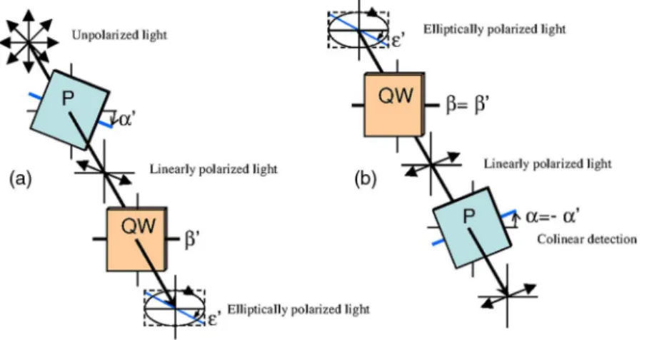
Fig. 1 Sketch of an example of the optical imaging system with linear polarizers (P) and quarter-wave plates (QW). (a) Generation of the elliptically polarized light in the illumination path. (b) Analysis of elliptically polarized light in the detection path. The polarization ellipse of the illumination and the detection can be described by the rotation angles α and α0of the horizontal axis of the linear polarizer and the rotation angle β and β0of the fast axis
of the quarter-wave plate. The ellipticities ε and ε0are defined by ε ¼ β − α and ε0¼ β0− α0. Copolarization detection is obtained for α ¼ α0, β ¼ β0,
and ε ¼ ε0.
polarizations and with different optical properties and ellipti-cally polarized light in Fig. 2(b) and 2(c). The MFP0 scale takes the scattering and absorption coefficients into account leading to a quasi independence of the descriptor on these parameters [Fig. 2(c)], while for depolarized light, a strong dependence on μa and μs persists [Fig. 2(b)]. Even if the
MFP0 scale also accounts for the anisotropy factor g, there is still a relatively strong dependence on g for all polarizations as well as depolarized light, especially if the anisotropy factor is high (Mie scatterers), because of its influence on the MFP0scale.
The backscattered intensity Ioðr; ϕÞ of the co- and
cross-polarized channels is obtained by counting all backscattered photons collected in a given polarization channel. A probability PðRÞ can be defined for backscattered photons emerging at radial distance R per unit pixel length:
PðRÞ ¼ ZR r¼0 Z2π ϕ¼0 rIoðr; ϕÞdrdϕ: (2)
This integral probability [e.g., Fig. 2(a) right] takes into account the diversity of the different radial patterns of the
polarized backscattered channel measurements. A radial-descriptor Rchas been defined in Ref.13for linear polarization
channels: ZRC 0 PðRÞdR∕ Z∞ 0 PðRÞdR ¼ 0.9. (3)
It has been adopted here for general elliptical polarization channels because it allows accounting for both radial extension of the backscattered signal and the diversity of the intensity pro-files. The evolution the radial descriptor RChas been analyzed in
the same way as ZC.
3 Results and Discussion
A complete correlation between the two descriptors has been found: Fig. 3 gathers all the simulation results obtained under the large range of optical properties, for both descriptors. The influence of optical properties and different polarizations on the relation between the MVD and the radial intensity dis-tribution are summarized in this figure, with a description pre-viously introduced by Liu et al.13These results are consistent with those reported in Ref.13, though for linear polarization and with a different depth indicator. To our knowledge, the present study reports for the first time that this behavior is main-tained whatever the polarization. The correlation between the two descriptors is very linear for different maintaining polariza-tions and even for depolarized light. A linear curve can be fitted with the data having a slope 0.33, an ordinate at the origin of 0.34, and standard deviation of 0.10. Note that all results were obtained by considering an infinitely narrow pencil beam with normal incidence to the surface. The slope of this curve has to be considered as a maximum value as the depth accessible under a non-normal incidence illumination will be shallower. Interestingly, one can thus express in synthesized form the following approximation, when all quantities are expressed in metric units:
Zc≈ Rc∕3þ ð3½μaþ ð1 − gÞμsÞ−1¼ Rc∕3þ D; (4) Fig. 2 (a) Examples of (left) histograms of mean visitation depth (MVD)
and (right) probabilities P for backscattered photons emerging at radial distances R, for different maintained polarizations [• linear, ▪ elliptical (ε ¼ 0.05π), ▴ elliptical (ε ¼ 0.1π), ▾ elliptical (ε ¼ 0.15π), ♦ circular (ε ¼ 0.25π), α ¼ 0.25π for all simulations, and + depolarized light] on a MFP0’ scale (μ
a¼ 0.5 cm−1, μs¼ 100cm−1, g ¼ 0.8: 1 MFP0¼
488 μm). (b) Evolution of the depth-descriptor ZCfor depolarized light
(cross-linear measurement) as a function of μs, μa, and g. (c) Evolution of
ZCwith different polarizations [same markers as (a)] as a function of μs,
μaand g.
Fig. 3 Evolution of ZC(probed depth) as a function of Rc(radial
exten-sion of the backscattered intensity). Color code represents the polariza-tion state: linear (dark blue), elliptical (ε ¼ 0.05π) (clear blue), elliptical (ε ¼ 0.1π) (turquoise), elliptical (ε ¼ 0.15π) (green), circular (ε ¼ 0.25π) (orange) [α ¼ 0.25π for these simulations], depolarized (red). Three dif-ferent markers are used for the difdif-ferent optical parameters: absorption coefficient μa(×), scattering coefficient μs (▵), and anisotropy factor g
(○). Inset: Zoom in the region probed by polarized light. Red line: fitting curve obtained by linear regression.
Journal of Biomedical Optics 016007-3 January 2013• Vol. 18(1)
where D is the diffusion constant as defined in the diffusion approximation.12 We have thus introduced a general formula
linking the radial extension of the measurable backscattered intensity to the depth extension of the probed volume, whatever the polarization channel used. Moreover, as the optical proper-ties (anisotropy factor, absorption, and scattering coefficients) can be retrieved by analyzing the morphology of the backscat-tered polarized signals,14one can estimate the value of MFP0(or
equivalently D). This leads unambiguously to an estimation of the probed depth by measuring Rc.
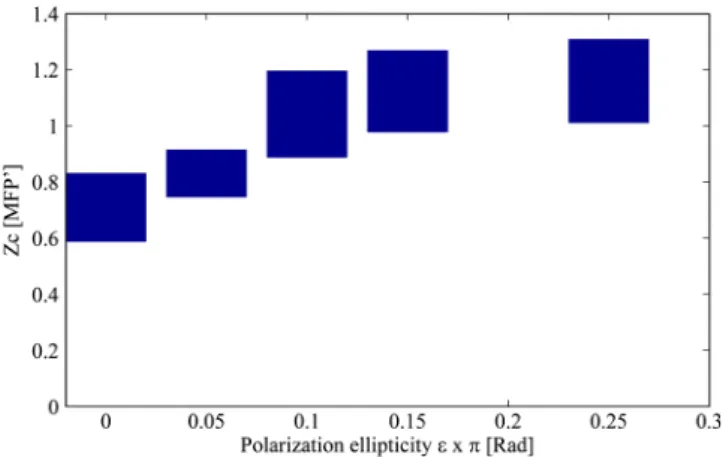
The limited depth extension of the volumes probed with different polarization channels is clearly highlighted with the chosen color code. It is shown that polarization maintaining channels will probe volumes larger as the polarization ellipticity increases. One can also verify that there is no intersection between volumes probed by depolarized and by polarized light. Interestingly, to illustrate this purpose, one can plot (Fig.4) the
evolution of the maximum and minimum values of ZCas a
func-tion of the polarizafunc-tion ellipticity ε: tuning the optical compo-nents in order to select a given polarization channel allows to probe scattering media up to specific depths, well defined if the optical properties are known.
To fix the ideas, specific calculations have been done for different types of tissues such as skin or brain tissues. The choice of the tissues is motivated by the fact that, for these tissues, conventional two-dimensional (2-D) intrinsic optical imaging techniques is the main optical technique used. In these cases, the present imaging technique could offer new opportu-nities in probing selectively the depth of these tissues allowing a more precise identification of the sources of the measured sig-nal. The results of the calculations are summarized in Table1. This table shows the probed depths, accessible by polarization gating, can be of few hundreds of microns. This corresponds pre-cisely to the depths extensions thought in many applications such as in skin cancers or exposed cortex screening, usually monitored with 2-D intrinsic optical imaging techniques, with no depth res-olution. The present polarization gated technique can as well pro-vide functional information and offers the advantage of being simple, with possibly fast data acquisitions.
4 Conclusion
This paper has shown that the use of elliptical polarization allows selection of photons which probed a specific depth, in a range defined by: (1) a minimum depth obtained by measuring the linear polarization maintaining signal; and (2) a maximum depth with the circular polarization maintaining signal. This allows tuning elliptical polarization in order to select a given probed depth under the condition of known optical properties. Furthermore, it was demonstrated that the probed depth is fully related to the backscattered radial extension for all polarizations. The relation found for different polarized illuminations applies also to depolarized light. The formulation allows prediction of the expected probed depth if the optical properties of the
Table 1 Depth-indicator ZCcalculated with optical properties corresponding to different types of tissues. Depths are reported in [MFP] unit and there
corresponding values in μm. The values of the optical properties correspond approximately to the values reported in Ref.15and references therein, at the wavelength 633 nm. Tissue Absorption coefficient μaðcm−1Þ Scattering coefficient μsðcm−1Þ Anisotropy factor gð−Þ MFP (μm) Depth-indicator ZC Linear Elliptical ε¼ 0.1π Circular Multiple scattering [MFP] (μm) [MFP] (μm) [MFP] (μm) [MFP] (μm) Examplea 0 100 0.92 100 7.7 769.5 14.8 1476 16.7 1667 67.5 6750 Human skin 3.2 168.6 0.81 59.3 3.4 200.1 4.6 271.8 5.8 343.1 8.3 491 Pork skin 1 492.6 0.95 20.3 12.7 256.9 23.5 476.6 26.0 528.6 40 812 Aorta 0.52 316.4 0.87 31.6 4.5 142.3 7.9 249.7 9.2 291.2 22.8 719 Gray matter 2.7 357.1 0.94 28 9.1 254.9 17.1 477.9 18.8 525.3 23.1 647 White matter 2.2 534.8 0.82 18.7 3.8 70.1 5.5 102.8 6.6 123.4 13.2 246 Uterus 0.35 393.7 0.69 25.4 2.6 65.9 3.1 77.3 3.5 88.3 10.5 267
aWhich is an example representing the most favorable situation for light penetration in depth in biological tissues (nonabsorbing, forward scattering).
These values are also those used by Stockford et al. in their simulations.9
Fig. 4 Evolution of ZC(probed depth) as a function of the polarization
ellipticity ε. The extension of the bars is bounded by the maximum and minimum values found for the range of optical properties explored.
investigated medium and the illumination polarization are known. The formulation is valid for a wide range of optical parameters and for all polarization channels.
References
1. F. C. MacKintosh et al., “Polarization memory of multiply scattered light,”Phys. Rev. B40(13), 9342–9345 (1989).
2. S. G. Demos and R. R. Alfano, “Optical polarization imaging,”Appl. Opt.36(1), 150–155 (1997).
3. S. Morgan and M. Ridgway, “Polarization properties of light backscat-tered from a two layer scattering medium,”Opt. Express7(12), 395–402 (2000).
4. D. Bicout et al., “Depolarization of multiply scattered waves by spherical diffusers: influence of the size parameter,” Phys. Rev. E
49(2), 1767–1770 (1994).
5. L. Wang, S. L. Jacques, and L. Zheng, “MCML—Monte Carlo model-ing of light transport in multi-layered tissues,” Comput. Methods Program. Biomed.47(2), 131–146 (1995).
6. J. Ramella-Roman, S. Prahl, and S. Jacques, “Three Monte Carlo programs of polarized light transport into scattering media: part I,”
Opt. Express13(12), 4420–4438 (2005).
7. F. Jaillon and H. Saint-Jalmes, “Description and time reduction of a Monte Carlo code to simulate propagation of polarized light through scattering media,”Appl. Opt.42(16), 3290–3296 (2003).
8. S. P. Morgan and I. Stockford, “Surface-reflection elimination in polari-zation imaging of superficial tissue,”Opt. Lett.28(2), 114–116 (2003). 9. I. M. Stockford et al., “Analysis of the spatial distribution of polarized light backscattered from layered scattering media,”J. Biomed. Opt.7(3), 313–320 (2002).
10. W. S. Bickel, “Stokes vectors, Mueller matrices, and polarized scattered light,”Am. J. Phys.53(5), 468–468 (1985).
11. S.-H. Tseng et al., “Investigation of a probe design for facilitating the uses of the standard photon diffusion equation at short source-detector separations: Monte Carlo simulations,”J. Biomed. Opt.14(5), 054043 (2009).
12. V. V. Tuchin, Tissue Optics, SPIE, Bellingham, WA (2007). 13. Y. Liu et al., “Investigation of depth selectivity of polarization gating for
tissue characterization,”Opt. Express13(2), 601–611 (2005). 14. J. Falconet et al., “Analysis of simulated and experimental backscattered
images of turbid media in linearly polarized light: estimation of the anisotropy factor,”Appl. Opt.47(31), 5811–5820 (2008).
15. W. F. Cheong, S. A. Prahl, and A. J. Welch, “A review of the optical properties of biological tissues,” IEEE J. Quant. Electron. 26(12), 2166–2185 (1990).
Journal of Biomedical Optics 016007-5 January 2013• Vol. 18(1)