Design and Development of a Transfer System for an
Automated Packaging Machine
MASSACHUSETTS INSTITUTE
by OFTECHNOLOGY
SEP 19 2019
Efstratios Moskofidis
LIBRARIES
B.Sc. Mechanical Engineering
ARCHIVES
RWTH
Aachen University, 2018
Submitted to the Department of Mechanical Engineering
in partial fulfillment of the requirements for the degree of
MASTER OF ENGINEERING IN ADVANCED MANUFACTURING AND DESIGN
AT THE
MASSACHUSETTS INSTITUTE OF TECHNOLOGY
September 2019
© Efstratios Moskofidis, MMXIX. All rights reserved.
The author hereby grants to MIT permission to reproduce and to distribute publicly paper and electronic copies of this thesis document in whole or in part in any medium now
knpwn or Pereafter created.
Signature redacted
Signature of Author:________
SoEfstratios Moskofidis Department of Mechanical Engineering
MITLibraries
77 Massachusetts Avenue
Cambridge, MA 02139
http://Iibraries.mit.edu/ask
DISCLAIMER NOTICE
Due to the condition of the original material, there are unavoidable flaws in this reproduction. We have made every effort possible to
provide you with the best copy available. Thank you.
The images contained in this document are of the best quality available.
Design and Development of a Transfer System for an
Automated Packaging Machine
by
Efstratios Moskofidis
Submitted to the Department of Mechanical Engineering on August 09, 2019 In partial Fulfillment of the Requirements for the Degree of
Master of Engineering in Advanced Manufacturing and Design
ABSTRACT
In this thesis, the design and development of an automated packaging machine capable of transitioning bulk vials into containers of 100 nested vials is presented. Specifically, this thesis focuses on the design, development and production of a transfer line as part of the aforementioned machine. After being fed into the sorting and orienting stage in loose bulk, the vials are transferred into the packaging stage through the transfer line. The designed machine will contribute to the reduction of labor costs and increase reliability regarding the exact number and orientation of the vials inside the package. After a concise overview of the motivation and objectives of the project as well as a brief reference to the term industrial automation, the design and development of the transfer line is described in detail.
Thesis Supervisor: David E. Hardt
Acknowledgements
This thesis is the result of both dedicated individual work and team spirit. I would like to thank the following individuals for their contributions to the outcome of this project, the unforgettable experience I had the honor to live as a graduate student at MIT and the positive development of many aspects of my personality.
I would like to thank my teammates Diamy Fernandes, Siyang Liu, Steven Ratner and
Paul Zhang. Without their academic rigor and supportiveness, this project would have never had such a positive outcome. Beyond the project, I would also like to thank the rest of the MEng cohort, Dehui Yu, Bowen Zeng and Jessica Harsono, for being such
inspiring and phenomenal classmates during this amazing year.
I would like to thank Professor Dave Hardt for his patience and guidance, despite the
high requirements and tight timeframe of the M.Eng. thesis.
At our industry partner Waters Corporation, I would like to thank our advisors Jason Dion and Gabe Kelly, who granted us creative freedom and flexible site visits. Without their accommodations, our design process surely would have suffered.
Last but not least, I would like to thank the co-director of the MEng program, Jose Pacheco, for being always present and willing to help in both good and bad times.
Contents
1 In trod u ctio n ... 13
1.1 Background and M otivation... 13
1.2 Objectives... 15
1.3 S cop e ... 17
1.4 W ork Distribution... 17
2 Automation...19
2.1 Defining Automation... 19
2.2 Reasons for Automation Implementation... 20
3 System Overview...21
3.1 Vial Accepter and Orienter... 22
3.2 Transfer Line... 24
3.3 Vial Placement M echanism... 26
3.4 M otor Selection and Programming... 27
3.5 Vision System and Industry 4.0 Connectivity... 29
4 Preliminary Solution Ideas... 31
4 .1 G uid e R ail...3 1 4.2 Assembly of a Tubular Connection Part, Conveyor Belt and Turner...33
4.3 Assembly of a Tubular Connection Part, Solenoid and Turner ... 36
4.4 Assembly of a Tubular Connection Part, Rotational Flange and Turner ... 36
4.5 Assembly of S-shaped Tubular Connection Part, Solenoid and Turner ... 39
5 Final D esign...45
5.1 Prelim inary Version... 45
5.2 Final Version... . 53
6 Conclusions, Recommendations, and Future Work... 59
6.1 Conclusions... . 59
6.2 Future W ork... . 59
A Engineering Draw ings ... . 61
B Determ ination of m axim um roller length... . 79
List of Figures
1-1 Side view of a 1 ml QuanRecovery vial. Each vial has a length of 35 mm and a diameter
o f 12 m m ... 14
1-2 An advertisement for QuanRecovery vials and plates with the inclusion of chemistry so ck s [1]...14
1-3 A package containing 100 1ml vials with QuanRecovery coating... 15
1-4 Automated packaging machine prototype. The arrows indicate the flow of each vial
inside the machine throughout each stage... 16
3-l a, 3-lb Vial accepter and orienter. The white arrows indicate the flow of the vials while
entering the feeder in bulk and leaving it in a specific
orien tatio n ... 2 3
3-2a, 3-2b Transfer line. The white arrows indicate the flow of the vials throughout the
parts of the transfer line/packaging
m echanism ... 24
3-3Vial Placement Mechanism. The white arrows indicate the flow of the vials throughout
the parts of the transfer line/packaging
m ech an ism ... 26
3-4 State machine diagram for packaging process... 28
4-l a, 4-lb Guide rail, twisted version. The guide rail would receive the vials (A) and allow a horizontal and at the same time rotational movement around its axis in order to be
delivered in the desired orientation (B)... 32
4-2a, 4-2b Guide rail, looping version. The guide rail would receive the vials (A) and allow them to move according to the constructed path in order to be delivered in the desired orientation (B )...32
4-3 Tubular part which allows the transfer of the vials from the sorting and orienting stage to the transfer line. Appropriate cuts would have been implemented to both of its ends. Each vial would enter the part (A) in a vertical, downward orientation, fall through it with gravity being the only movement lever, and land on the conveyor belt after leaving the tube (B )... ... 3 4
4-4a, 4-4b Murtfeldt Plastics product turner [2]. Cans are used for the demonstration of the product's function, but the mechanism would have been the same for the vials. The vials, moving horizontally along the conveyor belt, would enter the turner (a) in a vertical, downward orientation, conduct a simultaneous translational and rotational movement dictated by the shape of the turner, and exit in the desired orientation
(b )...3 5
4-5a, 4-5b, 4-5c, 4-5d Each vial lands into the rotating flange. In case it lands on the bottom, it is on a slightly higher position, (as the bottom does not fit in the slot below), which enables it to come into contact with the bar and move according to the guide construct track
while rotating
[3]... . 3 7
4-6 Each vial lands into the depicted constrained space. It gets pushed (the square block which would have been connected to the solenoid is partially depicted) into the turner and
leaves it in the desired inclination... 39
4-7a, 4-7b, 4-7c 3D-printed prototype version (a) of the product turner. As can be observed in (b) and (c), the vial would enter the part in horizontal direction and be delivered into the packaging stage in the desired inclination of 45 degrees. Given the high lead time and costs associated with the option of outsourcing its production, it was 3D-printed at MIT facilities. The brittleness of resin (the material used) made it impossible to drill holes for the purpose of the part's connection with the transfer line chassis and therefore would have made
4-9 The vials are able to come out of the sorting and orienting stage in either orientation.
If the vial leaves that stage with its top, a hooking mechanism enables it to turn by 90
degrees, bringing it to the desired orientation. However, the fact that the diameter above the neck is almost equal to the diameter under it, would have made it hard for this m echanism to w ork [4]...43
4-10 The vials are able to come out of the sorting and orienting stage in either orientation. If the vial leaves that stage with its top, a hooking mechanism enables it to turn by 180
degrees, bringing it to the desired orientation. However, the disallowance for the inner side of the vial to get in touch with any part of the device or external substance made this type
of solution unsuitable [5]... . 43
5-1 Prototype CAD version of tubular connection part between the vial sorting stage and
the transfer line. The vials come out of the sorting and orienting stage (A) and exit the tube
(B) in the indicated orientation... . 46
5-2 One end of the tubular connection part was required to fit between the turner and the
first guide mount, as depicted on this CAD section. Its outer diameter was designed small
enough to fulfill this requirement and large enough to provide
rob u stn ess...4 6
5-3 Row of plastic rollers for the preliminary version of the final design. Each vial would
have been pushed (pushing block not indicated in the picture) into the roller raw, which
would prevent the vials from losing the desired
orien tatio n ... 4 7
5-4a, 5-4b Preliminary version of plastic roller row, installed on a 3D-printed twisted frame. Each vial will be pushed (pushing block not indicated in the picture) into the roller raw, which secures keeping the desired orientation as well as forcing the vial to rotate into the desired tilt. The twisted part was 3D-printed, having vertical holes on both walls for fixing it with threaded shafts. The shafts for the rollers, which are secured by e-clips, were
later replaced by threaded shafts and
5-5 Final version of plastic roller row, installed on a 3D-printed twisted frame, for the final design. The differences between the depicted version and the version presented in Figure 5-4 are the larger thickness of the side walls (which enables the use of larger threaded shafts for the installation and therefore provides higher robustness), the use of threaded shafts and nuts (the latter are not depicted) instead of e-clips and the color of the resin
m aterial...4 8
5-6a, 5-6b, 5-6c Cross-section sketch of the principle on which the rollers would function. The rollers (yellow) are kept on aluminum shafts (black) which are fixed on the walls by e-clips (not depicted). The rollers hang on the respective shafts at the lowest possible position when the vial (grey) is entering the row (a). Being pushed by the pusher so that it has enough lever to overcome the first roller's moment of inertia (b), the vial moves along the transfer line, lifting up the rollers it gets into contact with. Getting "trapped" between two rollers each time being pushed forward, it keeps the desired orientation
(c )...4 9
5-7 Geometrical determination of the position of the shaft a relative to the surface of the roller row frame. It was initially assumed that a maximum distance between the inner roller cycle and the shaft cross section of 0.2 in was reasonable. With b being the distance between the centers of the vial and shaft cross section, it can be derived from the depicted
sketch that a - 0.0625 + 0.2 = 0.47 + 0.25 + 0.125, meaning that a 0.7075 in.
Furthermore, b + 0.47/2 a, meaning that b 0.4725
5-9a, 5-9b The square part which would be pushing each vial into the roller row was made
of polycarbonate in order to have less friction during the guided linear motion on the
alum inum -m ade guides (b)... . 52
5-10 Prototype of the crank shaft mechanism. The motor (not depicted) would have been connected to the crank shaft via a shaft coupler. Its rotational motion would have been transformed into a translational motion by the loosely connected aluminum square block.
Appropriate bearings would have been necessary,
th o u gh ... 5 3
5-11a, 5-11b, 5-11c The U-channel, whose width was reduced at its one end in order to fit
between the side wall and the roller row frame (a), would be connected to the bowl feeder
through an installed sheet metal part (c)... 54
5-12a, 5-12b Modification of the polycarbonate square part (red), top view. The problem of the next vial (black) blocking the linear motion of the square part (a) was solved by
reducing the width of the latter over around 0.5 in of its length.
... ... 5 5
5-13 The cam is connected to the rotating motor shaft via a shaft coupler. The cam, which is rotating around a fixed axis, has a geometry which allows the pusher block to be displaced by around a vial diameter. The spring, which has been positioned between the constraining square end of the pusher block and a fixed mount, forces the pushing block to return to its initial position. Although not possible to observe in the picture, the square end would be attached separately via a thread inside the intermediate part between the front and back of the pusher block and a countersink screw...56
5-14 CAD-version of transfer line. With the core principles of the system remaining the same, adjustments were made due to time constraints and uncertainties regarding the
5-15 The cam is connected to the rotating motor shaft via a shaft coupler (side view). The cam, which is rotating around a fixed axis, has a geometry which allows the pusher block to be displaced by around a vial diameter. The spring, which has been positioned between the pusher block and a thin aluminum block on the roller row frame, forces the pushing
block to return to its initial position... . 57
5-16a, 5-16b Position of first roller (black) in the first version of the twisted part (a) and in the final version (b), top view. The length of the part was adjusted so that the first roller is aligned with the side walls (blue) of the 3D-printed part. Therefore, the vial (red) is
prevented from drifting to an angled
p o sition ... 5 8
B-1 Each roller was aligned at a different angle a relative to the walls. Therefore, its length had to be determined based on the angle a. X, which is the distance which has to be cut off the initial roller length L on both sides so that the roller fits in the gap, can be calculated as
follows: tana = 2x/D => x = D*(tana)/2. Therefore, y = L - 2x = L - D*tana. L can be
calculated by using the fact that the horizontal length of the turner frame gap is 35 mm (or
1.37795 in): L = 1.37795/cosa. Therefore: y = 1.37795/cosa - 0.5tana. The a-values can
Chapter 1
Introduction
This chapter outlines the background and motivation behind Water's request for an automated packaging machine to be designed and constructed. Furthermore, the project's objectives, scope and work distribution are reviewed to provide the reader with a proper understanding of the program's purview.
1.1
Background and motivation
The analytical laboratory instrument manufacturing company, Waters, produces a comprehensive range of system solutions for the life sciences industry. Liquid chromatography and mass spectrometry machines are the center of Waters' product offering. As a holistic supplier of its services, Waters provides auxiliary goods to support
its laboratory instruments.
One such auxiliary product, QuanRecovery, was introduced to the market in Q2,
2019. QuanRecovery minimizes the effect of sample loss due to non-specific binding and
ionic interactions through a proprietary treatment. This treatment is applied to the interior surface of 1ml vials, shown in Figure 1-1, that are sold to laboratories globally. Through a successful marketing campaign, propelled by the addition of free chemistry socks with every order, a well-known favorite amongst scientists and procurers alike, Waters' obtained excellent early adoption after considerable initial interest as a result of marketing efforts and product quality. Figure 1-2 displays an advertisement of the QuanRecovery vials along with the aforementioned chemistry socks.
Figure 1-1: Side view of a 1 ml QuanRecovery vial. Each vial has a length of 35 mm and a diameter of 12 mm.
QuanRecovery
Figure 1-2: An advertisement for QuanRecovery vials and plates with the inclusion of chemistry socks
[2].
Waters sells the 350pl vials in packs of 100, as shown in Figure 1-3. Experimentation indicates a human takes 2 minutes to package 100 vials by hand. With an
the introduction of this automated system into the first QuanRecovery production line, Waters will be able to label the packages as '100'.
Figure 1-3: A package containing 100 1ml vials with QuanRecovery coating.
The downsides of Waters' current packaging methods prompted the company to enlist help from the 2019 MIT MEng cohort to develop an automated solution that would robustly place 100 vials into each container. This thesis describes the solution that was created to replace Waters' human packaging system.
1.2
Objectives
The project proposed to design an automated system that would take a pile of vials and correctly place them facing upwards in groups of 10 by 10 to fill a 100-vial container in a repeatable manner. The key objectives were as follows:
- Receive a bulk pile of unoriented vials and place them in a 10 by 10 matrix facing
- Minimize external particulate from accumulating within the vials.
- Validate that 100 vials are placed into each package.
- Keep development and production costs under $10,000.
1.3 Scope
The project scope was contained to developing and building a functional prototype, displayed in Figure 1-4 below, that could be used to demonstrate the potential for the proposed automated machine. Once the prototype was complete and working, engineering drawings of each custom component were made along with an assembly and
user manual. This way, Waters could manufacture and operate future iterations of the machine as production levels deemed necessary.
1.4
Work distribution
The system was split into five main tasks as listed below:
(1) Orienting the vials from a bulk unorganized state.
(2) Feeding the oriented vials into the packaging mechanism through a transfer line.
(3) Packaging the vials into trays.
(4) Validating the packaged vials to ensure they are correctly placed.
(5) Motor selection and control.
Initially, all of the group members worked on each of the tasks together. However, after the inceptive brainstorming stage was complete, the five tasks were split between each of the teammates for the sake of efficiency. The owners of each task are as follows: (1)
Zhengyang Zhang, (2) Efstratios Moskofidis, (3) Steven Ratner, (4) Siyang Liu, (5) Diarny
Chapter 2
Automation
This chapter presents a definition for automation; one that will be used as the premise for why the packaging machine creation is relevant in the 21st century. Furthermore, the societal impact of automation is briefly explored.
2.1 Defining Automation
In the history of the manufacturing industry, the transition from hand-made to automated work has taken many forms over the last quarter-century. Current buzzwords such as machine learning, data analytics, artificial intelligence and the Internet of Things (IoT) are redefining what popular belief would have once suggested was the face of automation: robotics. Even over the last five years, many questions have been raised on what truly defines automation and where it is going. In the workplace there are concerns over the ethics of replacing the human being with a machine. In the home there is concern over data collection and privacy, where both logical and physical machines are recording what we say, tracking products and services we prefer, and tailoring the media we consume to our analyzed behaviors. It is easy to get lost in the many thousands of online articles warning of the impending danger of becoming a more mechanized civilization. However, from the perspective of an engineer, we must see the state of the art for what it is in order to extract from the hysteria the truly plausible implications of increasing automation.
For the purposes of this thesis, automation will be defined as the use of a computer-guided mechatronic system to perform a physical task with little to no human intervention. The system may also collect data on its environment and respond to stimuli in that environment. However, it is not necessary for the system to do so in order to abide by this crude definition of automation. In this thesis we will focus specifically on what the human being relies on the machine to do and what types of mechanical intervention can be considered automation by this definition. We will explore the motivations for implementing physical automated systems on the factory floor and not software-only
solutions such as data analytics and machine learning. These are for another technical discussion that is out of the scope of this particular thesis. For more detailed work on Industry 4.0 integration for this project, refer to [3].
2.2 Reasons for Automation Implementation
Increasing throughput, reducing injury from repetitive motions or boredom, and making manufacturing less costly may immediately come to mind as the main motivations for the manufacturing industry to implement automation. With a computer-controlled machine the benefits are nearly immediate to understand: the company no longer has to pay an employee's hourly wage, insurances or other benefits just so he or she can continuously perform a single task or flow of tasks. The employee may then seek more engaging, personally fulfilling or challenging work.
Chapter 3
System Overview
This chapter provides a synopsis of the automated vial packaging machine's features, layout, and operation. Specifically, the system is broken down and detailed through its five principal components.
As briefly mentioned in Chapter one, vials are currently picked and placed in trays one at a time by unskilled labor. In addition to the inefficiency, the lack of quality control and validation method have resulted in inconsistent final product quantities. Therefore, a more reliable and controlled packaging process is required to maintain Waters' standard in delivering high quality products.
Before addressing the problem, there are some design parameters and restrictions that need to be taken into account. The company had its own requests for the design and performance of the machine. Ideally it should be easy to assemble, with as many parts being commercially available as possible. Production-ready drawings should be made available for any custom components. It should also be as close to table-top size as possible and have a production rate of no less than what was achieved using human labor (one completed vial tray about every two minutes). The machine should first be capable of packaging plastic vials, but ideally it should handle both glass and plastic vials with little to no modification. Finally, a way of inspecting the trays for quality (specifically the number of vials packaged per tray) can be implemented.
Working Environment Restrictions I Material Selection
In order to maintain the sterile conditions of the product, the machine must be composed of plastics that do not outgas or produce residue or particulates. Machine oils and greases must be avoided unless they are high enough in viscosity to prevent coagulation in critical contact areas.
IIEnergy Sources
One significant challenge for the design of this system was the lack of access to shop air. Since the machine is located in a cleanroom environment, compressed air cannot be used. Therefore, the only source of energy for mechanical actuation is standard 120VAC electricity at 60Hz.
IIIConnectivity
The work area does not have wireless network access. Any data collection and communication must take place over Ethernet access.
Part Handling Restrictions
The most critical surface of the vial is the inner lining starting at the opening. No mechanical or chemical contact is allowed between this surface and any machine element used. Particulates must not collect inside the vial. Due to the small overall dimensions of the vial, it is not practical to implement any manipulator designed to handle individual units.
3.1 Vial Accepter and Orienter
As the first stage of the automated machine, the vial sorting system takes in loose vials in bulk and outputs singulated vials, all with the same final orientation. Figure 3-1 shows the setup of the vial sorting system, resembling a bowl feeder.
(a)
(b)
Figure 3-1a, 3-1b: Vial accepter and orienter. The white arrows indicate the flow of the vials while entering the feeder in bulk and leaving it in a specific orientation.
The primary functions of the sorting system are achieved by the three components: the center disc that accepts loose vials and transports them, the bowl with scallops that
singulates vials, and various selectors that retain vials facing the desired orientation and rejects the rest (Figure 3-1b). The inclined center disc rotates, applies centrifugal force on vials, and propels them onto the scallop pockets. The bowl also rotates continuously and moves the vials past series of passive mechanical selectors which reject vials that are not properly nested within the scallops and not facing the right orientation. The rejected vials are returned to the center of the bowl and recirculated; the retained vials are pushed out of the bowl and move on to transfer line.
For a more detailed overview on the design, development, and performance of the vial sorting mechanism, refer to [9].
3.2 Transfer Line
The transfer line's functions are the following: receiving the sorted vials from the aforementioned vial sorting and orienting stage, all in the same orientation, and delivering them to the vial packaging mechanism in the desired orientation and inclination.
Figure 3-2: Transfer line. The white arrows indicate the flow of the vials throughout the parts of the transfer line/packaging mechanism.
The transfer line consists of three main subsystems: the connecting part to the vial sorting and orienting stage, the vial reception and pushing mechanism, and the twisted roller row.
Each vial with correct orientation enters the connecting part and is transferred through the latter into the constrained vial reception space. The vials are pushed into the roller row by a square-shaped pushing block, whose linear, periodical motion is secured through side guides. The key component of the vial pushing mechanism is the cam, whose rotational motion is converted into the block's translational motion, enabling the vials to move towards the packaging stage. The installation of a compression spring allows the block to return to its initial position.
The roller row consists of a 3D-printed frame, whose twisted surface enables the vials to move towards the packaging mechanism and simultaneously rotate around their center of mass, therefore having the desired inclination when entering the packaging stage, as well as properly inclined rollers, which prevent the vials from losing the desired orientation.
For a more detailed overview on the design and development of the transfer line, refer to chapters four through six in this thesis.
3.3 Vial Placement Mechanism
The vial placement mechanism performs two primary tasks: loading the oriented vials into a tray and queueing empty trays to be loaded with vials. Figure 3-3 below displays a diagram of the placement mechanism with the major components labeled.
Figure 3-3: Vial Placement Mechanism. The white arrows indicate the flow of the vials throughout the parts of the transfer line/packaging mechanism.
When a tray is loaded with 100 vials, the tray slider moves down to the offboard ramp, where the full tray is able to slide out towards the vision system. After the full tray has been discharged, the tray slider moves back up; permitting the next empty tray to fall into place on the tray slider. For a detailed overview of the vial placement mechanism, please refer to [4].
3.4
Motor Selection and Programming
The machine utilizes several motion axes to achieve reliable vial packaging. The following list describes all motors and actuators used on the machine:
Vial rake - 24 VDC stepper motor (operating a cam)
Tray lead screw - 24VDC stepper motor (direct drive)
Vial-biasing block - 120VAC linear solenoid
Transfer line feeder - 24 VDC stepper motor (operating a cam)
Rotary bowl feeder (center stage and sorting ring) - Teknic@ ClearPathTM servomotor
with integrated motor controller
Sensors are placed throughout the machine layout to provide feedback on the machine's performance:
Transfer line sensor: standard 24VDC optical sensor Vial counter: standard 24VDC optical sensor
Rake actuation counter: 24VDC microswitch, wired normally open
Lead screw initial/final positions: 24VDC microswitch, wired normally open
The motion is controlled using a PLC and HMI by IDEC. The state machine diagram is provided below (see Figure 3-4) to describe the logical actions for the packaging process.
For a detailed overview of the motor selection and programming of the machine,
Initialize lead screw -position
Initialize vial rake
cam position
j
Reset all counters
- Check for vials If transfer line is empty Start rotary fee
If transfer line is full
Stop rotary feeder
Check vials in rake If rake has 10 vials
If rake has c10 vials Stop feeding rake
CFeed rake from Reset rake count
transfer line
Dispense vials Add 1 to row count
If row count <10 Check row count ""A Ifrow count odd If row count even
If row count = 10
Eject tray
Tra inpcto
3.5 Vision System and Industry 4.0 Connectivity
The last stage of the packaging machine is automated inspection and data transfer. The machine needs to produce exactly 100 vials packaged in a plastic tray in a robust fashion. Therefore, an automated inspection system is developed to confirm the correct number of vials in a package. In addition, Waters needs to keep track of the manufacturing data of the packaging machine since the packaging process happens at a remote offsite location. Hence, a data delivery system is also developed to post operational data in a server so that Waters can monitor the machine performance in real time. the automated inspection system is enabled by a Raspberry Pi 3 Model B+ and a Raspberry Pi NoIR Camera module with infrared capability. As a completed package of vials exits the packaging stage, it enters a black box with the camera installed on the ceiling. The black box is selected in order to create a controlled lighting environment for the camera to deliver a robust performance. Both white LEDs and Infrared LEDs are selected to provide adequate lighting inside the black box so that the camera can capture all the features in the package. The Raspberry Pi is set up with Python 3 and OpenCV to run feature recognition algorithms.
Once the image recognition algorithm finishes running. The output data is stored in the SD card with Raspberry Pi, which will be keeping track of the machine uptime and total number of properly packed packages that have been produced. Along with some other crucial operational data such as machine throughput rate and machine uptime, the data will be sent through ethernet to the Waters server for storage and inspection.
For a detailed view of the automated inspection and connectivity of the machine, please refer to [3].
Chapter 4
Preliminary Solution Ideas
In this thesis, the design of the vial transfer system, which enables the transfer of each vial from the sorting and orienting to the packaging stage, is presented. Whereas the final design
is thoroughly described in Chapter 5, a comprehensive overview of all preliminary ideas,
most of them being based on existing solutions and adjusted to the needs and restrictions of this project, is given in this chapter. This serves as a means of providing a clearer picture of the iterative thinking, designing and prototyping process which led to the final solution. In each section of this chapter, one preliminary solution system is explained, as well as the reasons why it was not further taken into consideration or parts of it were adjusted for further steps.
4.1 Guide Rail
An intuitive solution which would have required the smallest number of components to design, assemble and manufacture is the direct transfer of the vials from the sorting and orienting to the packaging stage via a guide rail.
As at a preliminary design stage of the sorting and orienting stage, the vials would come out of it in a vertical and downward orientation, the core requirement of the guide rail was to deliver the vials in a vertical position after turning them by 180 degrees relative to their initial orientation. Two versions of the guide rail were designed: a twisted (Figure 4-1) and a looping (Figure 4-2) guide rail.
A
Figure 4-la, 4-1b: Guide rail, twisted version. The guide rail would receive the vials (A) and allow a horizontal and at the same time rotational movement around its axis in order to be delivered in the desired orientation (B).
A
manufacturing would have only been feasible either by forming or 3D printing. Although the former process would have been able to deliver the required tolerances (given that the diameter of the vial is almost homogeneous across its height the tolerances would have been very high) with appropriate post-processing practices, it was neither available at MIT facilities nor at Waters' manufacturing plants. Therefore, outsourcing the production of the part would have been the only solution. Beyond the higher costs, outsourcing would carry high uncertainty regarding lead time (which would have most probably been high, given the complexity of the geometry as well as the post-processing requirements) and put limits on prototyping and testing opportunities. Given the availability of the numerous 3D printers at MIT, the latter manufacturing option would have been suitable in terms of prototyping, testing and iterating, but not capable of meeting the tolerance requirements.
- Uncontrolled transition: the speed at which the vials are getting out of the sorting and
orienting stage can be calculated and optimized up to a point through adjusting several design parameters, but it is impossible to actively control it. Therefore, even with a very precise alignment of the guide rail, a smooth fit of the vial into the guide rail would have never been guaranteed. There would have been a risk that one or more vials enter the guide rail in a horizontal instead of a vertical position, thus getting into the packaging stage in a wrong orientation.
-Jamming risk: The use of external substances, in this case oil or any other substance which
would decrease the friction coefficient between the vial and the contact surface, is prohibited. This added difficulties in guaranteeing a smooth motion of the vials along the path defined by the guide rail and increased the risk of jamming and blockage.
4.2
Assembly of Tubular Connection Part, Conveyor Belt and Turner
On the one hand very intuitive, on the other hand the most complicated solution idea to implement: a tubular connection part between the sorting and orienting stage and the transfer line, a conveyor belt and a turner.
As in the preliminary design idea described in the previous section, the vials would come out of the sorting and orienting stage in a vertical, downward orientation. Each vial would have been received by the transfer line through a tubular part which with proper cuts on both ends in order to allow the vial's movement towards the packaging stage, while still preventing it from falling back (Figure 4-3).
In A
Out
B
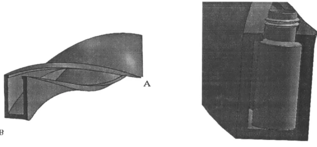
upwards, a 225 degree turn had to take place during the translational motion. An existing solution to this had been taken into consideration (Figure 4-4): the company Murtfeldt Plastics provides a plastic product turner which enables several kinds of products to perform a turn of any possible angle (the production of the turners is highly customized). Considering the high lead time and costs of the product, though, as well as the availability of 3D printers at MIT facilities, prototypes for this part were produced internally (see Section 4.4).
(a) (b)
Figure 4-4a, 4-4b: Murtfeldt Plastics product turner 15]. Cans are used for the demonstration of the product's function, but the mechanism would have been the same for the vials. The vials, moving horizontally along the conveyor belt, would enter the turner (a) in a vertical, downward orientation, conduct a simultaneous translational and rotational movement dictated by the shape of the turner, and exit in the desired orientation (b).
Two main pain points were associated with this transfer line solution, and led to the decision of not proceeding with this and pursuing different ideas:
- Tensioning: a conveyor belt not only consists of many different components, but also
requires a complicated and tedious tensioning process in order to be set up properly. Given the limited budget and time constraints for testing and prototyping, this has a critical drawback.
-Securing vertical position of the vials: this would have been the key issue for the viability
of this proposed solution, both regarding the landing of the vials from the tubular part onto the conveyor belt as well as their motion towards the packaging stage. For the latter aspect, the installation of vertical side rollers, being able to "wiggle" around the shafts they were installed on and therefore prevent the vials from tipping by being "trapped" between them,
would have been an effective solution. Immediately after landing onto the conveyor belt, though, only a very precise positioning of the first roller pair to prevent the vial from tipping as well as determination of the right tolerances the shaft diameter and the inner diameter of the rollers would have been able to guarantee that each vial stayed in a vertical position.
4.3 Assembly of Tubular Connecting Part, Solenoid and Turner
In order to overcome the drawbacks associated with a conveyor belt, an alternative idea to this described in the previous section would have been to enable the transfer of the vials to the packaging stage by a solenoid and a stationary surface instead of a conveyor belt. The fact that the speed of the pushing solenoid would not have been able to be controlled, though, would have increased the risk of tipping (also see Section 4.5).
4.4 Assembly of Tubular Connecting Part, Rotational Flange and Turner
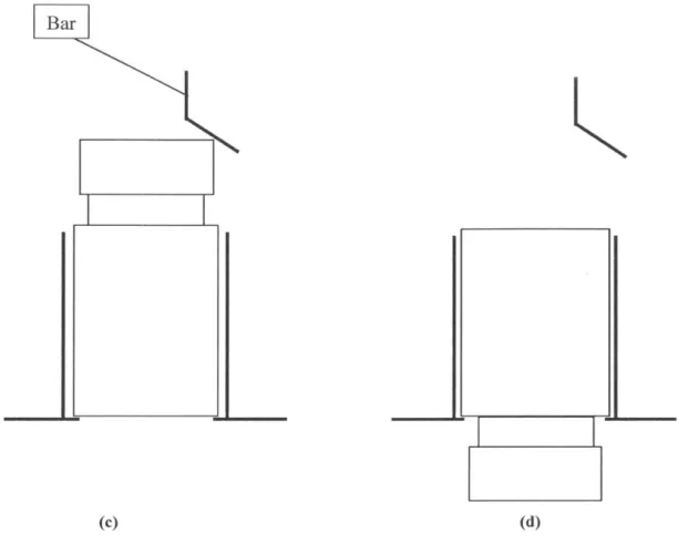
The solution idea which would have been the most demanding in terms of tolerances and testing efforts consisted of the aforementioned tubular connection part, a rotating flange and the aforementioned product turner. Inside the rotating platform, each vial would land into one of the flange's slots and be turned by 180 degrees via a guide construct installed on the stationary platform around the flange (Figure 4-5a-d).
At that preliminary stage, the design of the sorting and orienting stage allowed the vials to come out either way (downwards or upwards). A benefit of this solution, therefore, would
fall, follow the track of the guide construct and enter the turner in the desired orientation (Figure 4-5a,b).
Guid track 2OP
ALI (a) Guide track Bar Flange Vial Vial landing position (b)
Bar
(c) (d)
Figure 4-5a, 4-5b, 4-5c, 4-5d: Each vial lands into the rotating flange. In case it lands on the bottom, it is on a slightly higher position (c and d), (as the bottom does not fit in the slot below), which enables it to come into contact with the bar and move according to the guide construct track while rotating 161.
Two main pain points were associated with this transfer line solution, and led to the decision of not further proceeding with it and pursuing different ideas:
together, would have been necessary. Given the complexity of the vials' motion inside the rotating flange (a simultaneous rotational motion around the flange as well as around the vial's center of mass) as well as the small size of the vials, designing, manufacturing, prototyping and testing this solution would have been a tedious and time-consuming procedure.
4.5 Assembly of S-Shaped Tubular Connecting Part, Solenoid and Turner
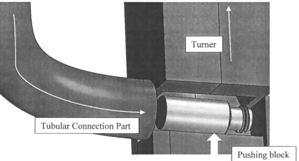
One major drawback of all aforementioned solution ideas was that the vials would have come out of the sorting and orienting stage in a vertical downward orientation. However, the sorting and orienting stage had successfully been adjusted so that each vial would enter an s-shaped tubular connecting part (Figure 5-1) horizontally and with its top and land into the vial accepting constrained space of the transfer line on its lateral surface (compare Figure 4-3 and Figure 5-1). This eliminated the risk of tipping right after leaving the tubular connecting part (Figure 4-6).
Tubular ConnectionPart
Figure 4-6: Each vial lands into the depicted constrained space. It gets pushed (the square block which would have been connected to the solenoid is partially depicted) into the turner and leaves it in the desired inclination.
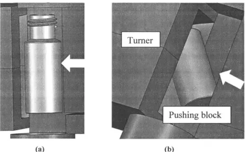
(c)
Figure 4-7a, 4-7b, 4-7c: 3D-printed prototype version (a) of the product turner. As can be observed in (b) and (c), the vial would enter the part in horizontal direction and be delivered into the packaging stage in the desired inclination of 45 degrees. Given the high lead time and costs associated with the option of outsourcing its production, it was 3D-printed at MIT facilities. The brittleness of resin (the material used) made it impossible to drill holes for the purpose of the part's connection with the transfer line chassis and therefore would have made appropriate constructs necessary.
This construction, though, carried two main disadvantages, which disqualified it for use in the final design version. Firstly, both directly after landing as well as during the motion along the turner, no appropriate solution was found to eliminate the possibility of one or more vials' "drifting" (meaning the vial's axis being non-parallel with the plane defined
by the turner's entrance, see Figure 4-8). Secondly, the use of a solenoid as a means of
moving the vials towards the packaging stage through the turner proved to be inappropriate, as it was not possible to control its speed (which would have dramatically increased the possibility for the vials losing the desired orientation inside the turner.
(a) (b)
Figure 4-8a, 4-8b: Demonstration of two possible directions the vial would have been able to enter the turner. As can be observed in (b), nothing prevents the vial from entering the turner in an undesired direction in case of drifting directly after landing. In case the vial's axis is not parallel with the plane defined by the turner's entrance while entering, its orientation will also not be as desired after the exit.
4.6
Other Existing Solutions
Two more existing solutions discussed in the very early stages of the project are worth mentioning (see Figure 4-9 and 4-10). They had been directly eliminated, though, due to several initial constraints and design parameters given.
\\lIIl
Figure 4-9: The vials are able to come out of the sorting and orienting stage in either orientation. If the vial leaves that stage with its top, a hooking mechanism enables it to turn by 90 degrees, bringing it to the desired orientation. However, the fact that the diameter above the neck is almost equal to the diameter under it, would have made it hard for this mechanism to work 171.
Figure 4-10: The vials are able to come out of the sorting and orienting stage in either orientation. If the vial leaves that stage with its top, a hooking mechanism enables it to turn by 180 degrees, bringing it to the desired orientation. However, the disallowance for the inner side of the vial to get in touch with any part of the device or external substance made this type of solution unsuitable [8].
Chapter 5
Final Design
In this chapter, the final design of the transfer line for the automated vial packaging and sorting machine is described. Before diving into the final solution, though, a brief overview of a preliminary version is provided. The reason why this preliminary prototype is not included in the previous chapter is that the concept had been very similar to the final solution and served as a crucially inspirational stage for coming up with the final design. Furthermore, most major components had been the same with the final design and are therefore already described in the following section.
5.1 Preliminary Version
The key benefit of the solution presented is the elimination of the tipping risk. The sorting and orienting stage had been adjusted so that the vials entered the tubular connection part as shown in Figure 5-1. They were able to land on their lateral surface into a constrained space, which also prevented them from drifting to a non-horizontal position, given that the
first roller was placed close enough to the landing vial (Figure 5-2).
The tubular connection part's design minimized the risk of the vials getting stuck at one of the two points with the highest curvature. At the same time, it enabled the vials' only motion lever, gravity, to be sufficient for their transfer through the entire tubular part. The part had been 3D printed out of resin, which had two main benefits: minimal friction between the vials (either plastic or glass) and the tubular part and therefore low chances for the vials to get jammed/stuck inside the tube, as well as feasibility of the part's curvature (as opposed to alternative solutions such as drilling or extrusion). The overall height of the part was adjusted to the final height of the vial sorting device (see next section), and the inner diameter as well as the curvature appropriately chosen to secure enough space for each vial to slide smoothly without getting stuck. Moreover, the outer diameter had been designed small enough to fit between the turner and the first guide mount (see Figure 5-2).
Feeder exit
direction
A
Pushing direction
B
Figure 5-1: Prototype CAD version of tubular connection part between the vial sorting stage and the transfer line. The vials come out of the sorting and orienting stage (A) and exit the tube (B) in the indicated orientation.
Turner
Outer tube diameter Guide mount
transfer line would consist of the previously described tubular connection part and a roller
row (Figure 5-3), with the vials entering the roller row and being transferred into the
packaging stage. As it was not able to deliver the vials into the packaging stage with the
desired inclination, the roller row depicted in Figure 5-3 was constructed only for testing
purposes and afterwards replaced by another roller row installed on a 3D-printed twisted
frame (Figure 5-4, Figure 5-5).
Figure 5-3: Row of plastic rollers for the preliminary version of the final design. Each vial would have been pushed (pushing block not indicated in the picture) into the roller raw, which would prevent the vials from losing the desired orientation.
Vial
Figure 5-4a, 5-4b: Preliminary version of plastic roller row, installed on a 3D-printed twisted frame. Each vial will be pushed (pushing block not indicated in the picture) into the roller row, which secures keeping the desired orientation as well as forcing the vial to rotate into the desired tilt. The twisted part was 3D-printed, having vertical holes on both walls for fixing it with threaded shafts. The shafts for the rollers, which are secured by e-clips, were later replaced by threaded shafts and nuts.
and therefore provides higher robustness), the use of threaded shafts and nuts (the latter are not depicted) instead of e-clips and the color of the resin material.
The use of plastic rollers dramatically decreased the risk of each vial losing orientation for two reasons: as the first roller would be positioned close enough to the landing space of the vial so that, in case the vial had a tendency to drift, it would not have enough lever to overcome the first roller. Furthermore, each time after being pushed by the vial behind it,
each vial would be "trapped" between two sequential rollers (Figure 5-6).
Roller
|Vial
(a)
(c)
Figure 5-6a, 5-6b, 5-6c: Cross-sectional sketch of the principle on which the rollers would function. The rollers (yellow) are kept on aluminum shafts (black) which are fixed on the walls by e-clips (not depicted). The rollers hang on the respective shafts at the lowest possible position when the vial (grey) is entering the row (a). Being pushed by the pusher so that it has enough lever to overcome the first roller's moment of inertia (b), the vial moves along the transfer line, lifting the respective rollers up. Getting "trapped" between two rollers each time being pushed forward, it keeps the desired orientation (c).
Initially, the approach described in Figure 5-7 was taken for the appropriate positioning of
the vials, assuming a maximum distance between the inner cycle of the roller and the cross-section of the shaft of 0.2 in to be reasonable. Several iterative steps had to be conducted, though, as at several points inside the row the pressure applied to the vials due to entrapment between two rollers (and therefore the force needed to be applied by the pushing in order to keep the flow going) was too high.
00.5 0.2 00.25 00.125
b
00.47
Figure 5-7: Geometrical determination of the position of the shaft a relative to the surface of the roller row frame. It was initially assumed that a maximum distance between the inner roller cycle and the shaft cross section of 0.2 in was reasonable. With b being the distance between the centers of the vial and shaft cross section, it can be derived from the depicted sketch that a - 0.0625+0.2=0.47+0.25+ 0.125, meaning that a =0. 7075 in. Furthermore, b + 0.47/2= a, meaning that b= 0.4725 in.
Shaft connected
0
to motor
Vial O
Figure 5-8: The crank shaft is connected to the rotating motor shaft via a shaft coupler. Thanks to the installation of guides on both sides, the pushing square block only has one translational degree of freedom. The loosely connected aluminum square block transforms the crank shaft's rotational motion into the pushing block's periodical translational motion, which enables the vial to enter the roller row.
After leaving the tubular connecting part and landing into the constrained space, each vial
would be pushed into the roller row by the following mechanism (Figure 5-8 and Figure
5-10), consisting of a polycarbonate square block (which would come into contact with each
vial to push it into the roller row), two guides with the respective guide mounts (Figure
5-9), an assembled crank shaft and an aluminum square part loosely connecting the crank
shaft and the block. The crank shaft would be connected to the motor via a shaft coupler.
(a) (b)
Figure 5-9a, 5-9b: The square block (a) which would be pushing each vial into the roller row was made of polycarbonate in order to have less friction during the guided linear motion on the aluminum-made guides (b).
Figure 5-10: Prototype of the crank shaft mechanism. The motor (not depicted) would have been connected to the crank shaft via a shaft coupler. Its rotational motion would have been transformed into a translational motion by the loosely connected aluminum square block. Appropriate bearings would have been necessary, though.
5.2
Final Version
Although the solution presented in Section 5.1 appeared functional and promising, several main alterations led to the final version of the design:
- As previously mentioned, the roller row and the turner were replaced by a roller
row with a 3D-printed, twisted frame (Figure 5-4, Figure 5-5).
- The tubular connection part was replaced by a connection part consisting of a
U-channel and a sheet metal adapter (Figure 5-11). As the tubular connection part (which would have to be adjusted so that it could be mounted to both the bowl feeder and the transfer line) would have been much larger than the prototype version (at a size that could not have been manufactured with the 3D-printing facilities at MIT), its production would have to be outsourced.
After conducting several trials, it could be inferred that the vials were only falling appropriately into the space if the u-channel was always filled. In order to ensure that this condition is always met while the machine is running, a sensor would be placed at the u-channel.
approximately 0.5 in (roughly one vial diameter) of its length. The purpose of this adjustment was avoiding a contact between the lip of the next vial and the front surface of the square part, therefore eliminating a jamming risk (Figure 5-12).
Pushing block
jamming
Side walls
(a) (b)
Figure 5-12a, 5-12b: Modification of the polycarbonate square part (red), top view. The problem of the next vial (black) blocking the linear motion of the square part (a) was solved by reducing the width of the latter over around 0.5 in of its length.
- The crank shaft mechanism was replaced by a cam-spring mechanism. The
complexity of the motion and the necessity of appropriate bearings (whose choice and testing would have been time consuming) were the main reasons for not following this option. The principle can be observed in Figure 5-13. The detailed geometry of the cam can be observed in [4].
Fixed spring mount Spring
0 0
0
Pushing block Cam
0 0
;No o
Square end part
Figure 5-13: The cam is connected to the rotating motor shaft via a shaft coupler. The cam, which is rotating around a fixed axis, has a geometry which allows the pushing block to be displaced by approximately a vial diameter. The spring, which has been positioned between the constraining square end of the pushing block and a fixed mount, forces the pushing block to return to its initial position. Although not possible to observe in the picture, the square end would be attached separately via a thread inside the intermediate part between the front and back of the pushing block and a countersink screw.
Motor
I
U-channelTre
TurnerIt is worth to mention that, while according to the original design the spring would be placed between the square end of the pushing block and a fixed mount, in the prototype assembly it was placed on the pushing block so that it would come into contact with a thin
aluminum block installed on the roller row frame and force back movement (see Figure
5-15), due to time constraints. Besides the lack of stability associated with this solution, the
presence of torque increases the jamming risk of the pushing block on the side guides.
Moreover, as opposed to a vertical installation of the cam and a square part as a contact point, the cam was horizontally positioned in the real prototype and a shorter pushing block with a rotational disk installed was used, with the latter being the contact point between the block and the cam. Besides tight time frames, a flat contact surface for the depicted cam geometry had been proved suboptimal in the vial placement stage. For more details, please refer to [1] and [4]. Spring Cam Pushing block Rotational disk O O
0
0 0Figure 5-15: The cam is connected to the rotating motor shaft via a shaft coupler (side view). The cam, which is rotating around a fixed axis, has a geometry which allows the pusher block to be displaced by
around a vial diameter. The spring, which has been positioned between the pusher block and a thin aluminum block on the roller row frame, forces the pushing block to return to its initial position.
- Last but not least, the length of the roller row frame was adjusted so that the first
roller was exactly aligned to the side walls (Figure 5-16) in order to decrease the risk of drifting of the vial during landing.
Roller Side walls
Shaft Vial
Figure 5-16a, 5-16b: Position of first roller (black) in the first version of the twisted part (a) and in the final version (b), top view. The length of the part was adjusted so that the first roller is aligned with the side walls (blue) of the 3D-printed part. Therefore, the vial (red) is prevented from drifting to an angled position.
Chapter 6
Conclusions and Future Work
6.1
Conclusions
Waters is encountering costs due to the handling of the vial sorting and packaging by unskilled labor as well as eventual inaccuracies regarding the number of vials in a package. The project team has successfully developed a prototype version of an automated vial
sorting and packaging machine.
This prototype version of the vial sorting and packaging machine has the ability of receiving randomly oriented and unsorted vials in bulk and automatically deliver them in
1Ox10 packages.
The prototype machine's transfer line, which is thoroughly described in this thesis, is capable of accepting the vials from the sorting and orienting stage as well as delivering those in the desired orientation and inclination to the packaging stage.
6.2
Future Work
Additional work is needed in order to transform the presented prototype into a machine ready for use in industry. Regarding the transfer line, several aspects need to be optimized:
- Decision between the two final design versions. Several analyses have to be
conducted in order to make a proper judgement, such as the performance of the cam interacting with a flat versus a curved surface or the implication of torque on the pusher block's life expectancy and friction against the side guides.
- Production of a more robust version of the connecting part between the sorting and
orienting stage and the transfer line. The sheet metal connecting part between the bowl feeder and the U-channel was only a temporary solution for the demonstration of the machine's functionality. It is obvious that a more robust solution must be
found. 4-axis CNC-machining and bending are probably the most suitable processes for this purpose.
Appropriate choice of material for the frame of the roller row, as plastic will not
provide a high life expectancy. Metal 3D-printing or 4-axis CNC-machining (the twisted surface will make things very complicated for the latter though) will probably be the most suitable processes to produce a version of the frame suitable
for use in industry.
Installation and testing of a sensor on the u-channel for the purpose of securing that
it is always filled. Several tests of the transfer line stage showed that its proper function is only guaranteed when both the u-channel and the roller row are permanently filled with vials.
Appendix
A
Engineering Drawings
A complete catalogue of engineering drawings used to construct the final prototype of the
4 3 F 2.49 2 N,' R 7 0 0 00 0
Stf ktt 00 NOTS$CALI 0tAWW* arvslol
DE UI
f
MAM $)GP"A' tWI A IS ?tt:I 7 0.75 E D C B F E D C B UAtS$O tL ESECO P
4 3 F1 K 8 03 C-4) 61
-K
I0.38
2 I IA
1.00 0.25 03 Bl 0141W61541N 0~ 0D 7 I K1 09 DNID V.*M 'NR. I-4 NAIl Akxntwjm 3 F ESECTIONA-A
D0C
0 B - - weIVB.AWIWO jlTMCam Mount
2 A 0/
C-E D C A4 4.4« 3 m n .2 m w so ew 2:e 1w n -a a 0.2C
103-iLJ__
T
1'-1.43i
00 0.63 0.40UNLESS 0OTAEWEE SPEICI`RD: .NN&6 N4 DMENSMS Ab24 Mj fit O1 kALI b AA W0MT 14W
OTLEANCE5 ; AR - ; PIN I Cc, IIS C4) 6 F E F-~2 6 -F E c B 4 3 121, I I 1 11 -11 1 .1 -1 ". I , " , " - -, - I I 1 11 -.1.11-
-'--F 2 -1 -s -F 1.23 0.201
1.7
0.40, s -. - --- -.- --2.10 E ; --- ---0 - 0 -as Bbl~s$ 47MEBWNE sPeC 0E 'Me": D~tM AND
*SwsNSa ASef l fSEro tSSEAK NASP D0 NOT SCAI OIAWNO SfSOSN
ENU C SEtNATNSP DATE ourNs uassAI AuNuQ "OR I"P I-'.---yEntry
![Figure 1-2: An advertisement for QuanRecovery vials and plates with the inclusion of chemistry socks [2].](https://thumb-eu.123doks.com/thumbv2/123doknet/14678720.558697/15.917.172.755.453.702/figure-advertisement-quanrecovery-vials-plates-inclusion-chemistry-socks.webp)


![Figure 4-4a, 4-4b: Murtfeldt Plastics product turner 15]. Cans are used for the demonstration of the product's function, but the mechanism would have been the same for the vials](https://thumb-eu.123doks.com/thumbv2/123doknet/14678720.558697/36.917.129.735.334.502/figure-murtfeldt-plastics-product-demonstration-product-function-mechanism.webp)