Design and Validation of an Avionics System for a Miniature
Acrobatic Helicopter
by
Kara Lynn Sprague
Submitted to the Department of Electrical Engineering and Computer Science
in partial fulfillment of the requirements for the degree of
Master of Engineering in Electrical Engineering and Computer Science
at the
MASSACHUSETTS INSTITUTE OF TECHNOLOGY
February 2002
@ Kara Lynn Sprague, MMII. All rights reserved.
The author hereby grants to MIT permission to reproduce and distribute publicly
paper and electronic copies of this thesis document in whole or in part.
Author...
...
Departmed (of Electrical Engineering and Computer Science
February 1, 2002
Certified by...
Accepted by...
Chairman, Department Committee on
...
Eric Feron
Associate Professor
Thesis Supervisor
Arthur C. Smith
Graduate Students
MASSACHUSETTSWSTITUTE
OF TECHNOLOGYBARKER
JUL 3 1 2002
Design and Validation of an Avionics System for a Miniature Acrobatic
Helicopter
by
Kara Lynn Sprague
Submitted to the Department of Electrical Engineering and Computer Science
on February 1, 2002, in partial fulfillment of the
requirements for the degree of
Master of Engineering in Electrical Engineering and Computer Science
Abstract
The avionics system for MIT's miniature autonomous helicopter was designed to safely
achieve a robust, high-bandwidth feedback control system while meeting physical
specifica-tions. The system has provided an efficient platform for testing new closed-loop controllers
and has yielded critical flight data used for developing simple models of small-scale helicopter
dynamics. The helicopter has demonstrated successful flight under augmented controllers
and has also performed three fully autonomous aileron rolls. The avionics system was used
to examine software validation and certification techniques. Furthermore, experience in
de-veloping the system illuminated a number of design and implementation details that could
be modified in future systems to improve robustness and safety.
Thesis Supervisor: Eric Feron
Title: Associate Professor
Acknowledgments
I would like to thank Vlad Gavrilets, Ioannis Martinos, Bernard Mettler, Eric Feron, Raja
Bortcosh, David Dugail, Jan De Mot, Enilio Frazzoli, Masha Ishkutina, Ben Morris, Nancy
Lynch, and Michael Earnst for their participation in and support of this project. The
original flight system architecture was developed by Vlad Gavrilets and Alex Schterenberg.
OpenGL open source software, developed by Jan Kansky of Lincoln Labs, was used for
the HILSim graphics environment. This project was supported by NASA grants to MIT
NAG2-1482, and CMU NAG2-1441, Draper Laboratory IR&D DL-H-505334 and the Office
of Naval Research, under a Young Investigator Award.
Contents
1 Introduction
1.1 The Cost of Validation . . .
Motivation . . . .
Objectives . . . .
2 Flight System 2.1 Vehicle Hardware . . . . 2.2 Avionics Package . . . . 2.2.1 Design Considerations 2.2.2 Avionics Description . 2.2.3 Safety Analysis . . . . 2.3 Onboard Software . . . . 2.3.1 Process: Bootstrap... 2.3.2 Process: Control . . . .2.3.3
2.3.4
2.3.5
2.3.6
2.3.7
2.3.8
Process:
Process:
Process:
Process:
Process:
Process:
Inertial Measurem Servo Controller B Global Positioning Barometric Altime Magnetic Compass Battery . . . .2.3.9
Process: Telemetry . ... .
2.4
Ground Station . . . .
...
.
. . .
. . .
. . .
. .
7
. . . .
8
10
. . . .
10
. . . .
12
. . . .
12
. . . .
13
. . . . 15. . . .
16
. . . .
17
. . . .
17
ent Unit . . . . 22 oard . . . . 23 Satellite Receiver . . . . 25 ter . . . . 26. . . .
27
. . . .
28
. . . .
29
. . . .
29
3435
3 Software Validation
3.1
Robust and Fault Tolerant System Properties
1.2
1.3
6
6
3.2 Hardware-In-The-Loop Simulator . . . .
3.3 Formal Verification . . . .
3.3.1 Daikon Invariant Checker . . . .
3.3.2 Polyspace Verifier . . . . 3.3.3 Formal Verification in Safety-Critical
3.4 Validation by Example: Flight Tests . . . .
4 Design Recommendations
4.1 Flight Software Specifications . . . .
4.1.1 Development Environment . . . . .
4.1.2 System Architecture Overview . . .
4.1.3 Process: Bootstrap . . . .
4.1.4 Process: Control . . . .
4.1.5 Process: Sensor Drivers . . . .
4.1.6 Process: Telemetry . . . .
4.1.7 Ground Station . . . .
4.2 Hardware Considerations and Upgrades . .
4.2.1 Modern-Day Avionics Components .
4.2.2 System Integration Solutions . . . .
4.3 Best Practices . . . . 4.4 Conclusion . . . . Systems Certification
36
39
40
41
42
42
44
44
44
45
45
46
46
47
48
48
48
49
50
51
. . . .
. . . .
List of Figures
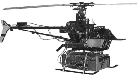
2-1 The flight vehicle equipped with avionics box. . . . . 11
2-2 Block diagram of the flight software system interactions. . . . . 18
2-3 Bootstrap process block diagram. . . . . 19
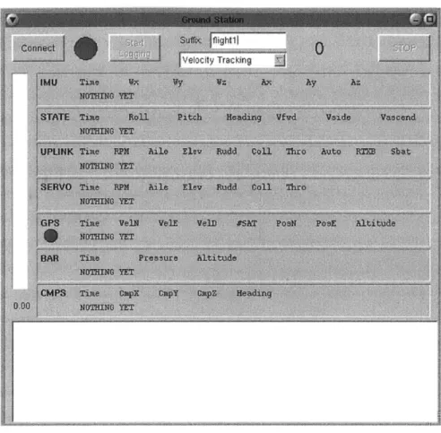
2-4 A screen shot from the ground display application. . . . . 31
Chapter 1
Introduction
With recent innovations in embedded and sensor technology, the use of automation in
mission-critical and life-sustaining systems has become prolific. The complexity of these
systems continues to grow as advances in both hardware and software technologies make
possible new applications. Unfortunately, what can be modeled as a linear growth in
sys-tem complexity translates into an exponential growth in safety assurance and verification
analysis to provide a commiserate level of flight system certification [5]. Unless such
sys-tems are implemented cleverly, taking advantage of modularity and clear specifications, the
cost of verification could very well be the limiting factor of the technical development in
such safety-critical fields. Given the highly volatile market for software and hardware
en-gineering and the speed at which technologies change, it is becoming increasingly difficult
for safety-critical systems to both maintain safety standards and exploit opportunities to
streamline and re-engineer systems to improve performance while reducing cost [6].
1.1
The Cost of Validation
The avionics industry provides a stunning example of how safety measures and concerns
may be stifling the development of potential applications and uses for advanced
technolo-gies. The software validation specifications of the Federal Avionics Administration require
assembly code-level checking to ensure that every branch of operating code is executed and
runs correctly. Such low-level code verification is necessary since compiler certification is
currently outside the capabilities of modern technology. Compilers are difficult to certify
because they generally have very complex, monolithic implementations and frequently take
advantage of dynamic memory allocation, which introduces a level of non-determinism that renders code validation extremely difficult. Since compilers cannot currently be certified, every piece of mission-critical software that is generated by the compilers must be validated, line by line. One consequence of these rigorous application-level requirements is that a soft-ware engineer working on a safety-critical flight system will typically produce only three lines of onboard code per day. Consequently, systems develop very slowly and changes are usually limited in scope. The high certification cost thus fosters an atmosphere of evolu-tionary development and a tendency to build upon existing monolithic systems rather than implement a more maintainable and modular architecture.
These tendencies away from more modular designs are problematic for a number of reasons. In addition to keeping component complexity at a minimum, the modularization of flight system architectures would also serve to enable the incorporation of commercial off-the-shelf components into new designs. Such systems would also be able to better keep up with the pace of modern technology, since upgrades would not require an overhaul of the entire system. Unfortunately, there is little motivation for the producers of commercial off-the-shelf components to validate their products. The safety-concerned market is only a fraction of the total market for many products with potential uses in the avionics industry. In many cases, this small market share is not enough to motivate commercial product manufacturers to undergo processes to validate and certify their components. Consequently, such readily-available parts can rarely be used in safety-critical systems.
1.2
Motivation
The field of unmanned aerial vehicles (UAV) offers a good test bed for examining flight safety certification procedures. Such systems are becoming more and more popular for their great maneuverability and numerous applications in both military and civilian domains. Possible military applications include surveillance, hazard detection, and even combat. UAV's may also prove useful for aerial photography, remote area exploration, crop dusting, and disaster
recovery operations. These aircraft provide the opportunity to streamline and develop
verification and certification processes for new technologies without directly endangering human life and at a much lower cost than their full-sized counterparts. UAV's thus offer much more room for experimentation in not only systems and control engineering but also
in validation and certification processes.
UAV's also offer tremendous advantages in terms of small-vehicle dynamics for techno-logical innovations. As sensor, communication, and computer technology evolve and shrink in size and weight, the potential for developing highly maneuverable unmanned vehicles in-creases. The miniaturization of technology is particularly relevant to the realm of small-scale unmanned aerial vehicles, in which large payloads exact high costs in maneuverability. As these craft become smaller in size, their moments of inertia decrease at an even faster rate, making them more agile. Miniature helicopters are among the most agile and maneuverable of the small-scale UAV's. Experienced radio-control (R/C) pilots of small helicopters rou-tinely execute acrobatic maneuvers such as steady inverted flight, pop-ups, hammerheads, and barrel rolls. Though some systems based on small helicopters have already demon-strated autonomous operation [9], they display fairly modest performance when compared to the acrobatic maneuvers accomplished by expert R/C pilots with similar platforms. The potential of such systems to serve in applications requiring varying levels of autonomy is tremendous, but has not been fully explored.
1.3
Objectives
MIT's Laboratory for Information and Decision Systems (LIDS) Helicopter Project began with an effort to learn pilots' strategies for executing maneuvers by studying pilot com-mands to the vehicle in flight [8]. Since vehicle states were not recorded, this groundwork supplied only limited insight into small-scale helicopter dynamics and thus motivated an ex-amination of the full state output of the helicopter to pilot inputs. Such data provides more insight into the dynamics of the vehicle in flight, thereby facilitating the development of models and controllers. The first introduction to MIT's instrumented, small-size helicopter equipped with a complete data acquisition system and capable of aggressive maneuvers was provided in [3]. The development of this test platform enabled the first fully recorded acrobatic flight in July of 2000. During this flight, pilot inputs and the state information of the vehicle were recorded while the helicopter performed hammerhead maneuvers and loops. The data collected from such flights has enabled the development and validation of a full-envelope helicopter model, as well as the design of the feedback control logic used in autonomous acrobatic flight. The ultimate goal of the helicopter project, to perform a
fully autonomous aggressive maneuver, was achieved on November 18, 2001. This flight, in which the helicopter performed three aileron rolls autonomously, demonstrated that the inherent agility of such systems is not severely limited by autonomous operation. Methods for verifying and validating the mission-critical software were evaluated in parallel with the development of the flight system, with the hopes that they would illuminate more efficient means to certify such systems and provide guarantees of safety.
This document presents the MIT helicopter and avionics system that was used to achieve autonomous aggressive flight. Chapter 2 details the technical aspects of the mechanical features of the helicopter and hardware involved in the design of the avionics system as well as the software system architecture and implementation details for the control system and ground station. Chapter 3 explores various system validation techniques and offers insight into the role these methods may play in the certification of safety or mission-critical
Chapter 2
Flight System
The flight system, shown in Figure 2-1, is composed of the helicopter, avionics system, flight software and ground station. The test vehicle is a derivative of an Xcell-60 helicopter manufactured by "Miniature Aircraft USA." The 60 cm3 engine and carbon fiber frame give the craft a total weight of about 10 lb. While the basic rotorcraft is known for its reliability as a stable acrobatics platform, the avionics system is entirely custom designed. Mounted in a single aluminum enclosure suspended below the landing gear of the helicopter, the avionics consist of a CPU, a power regulator, five sensors to provide closed-loop feedback, and batteries. All sensors, with the exception of a pilot command receiver and servo control unit, are commercial-off-the-shelf components and are rated as flight-ready. The onboard and ground station software is entirely implemented in C and runs on QNX 4.25, a popular real-time operating system. The high vibration levels of the rotorcraft, which can interfere with the operation of sensors and equipment are attenuated by a passive vibration isolation subsystem, which consists of an elastomeric isolator suspension system for the avionics box. Each of these subsystems is described in greater detail below.
2.1
Vehicle Hardware
The test vehicle, shown in Figure 1, is an Xcell-60 hobby helicopter powered by a mixture of alcohol and oil. This model is favored by many R/C pilots for its ability to perform acrobatic maneuvers. The vehicle includes a twin-blade rotor with a 5 ft diameter and frame weight of about 10 lb. The main rotor assembly features a fairly stiff hub joint, which, according to flight test data, provides a fast angular rate response to cyclic inputs.
Figure 2-1: The flight vehicle equipped with avionics box.
The assembly also includes a Bell-Hiller stabilizer bar, which augments servo torque with
aerodynamic moment to change the cyclic pitch of the blades and adds lagged rate feedback
to improve the handling qualities of the helicopter.
Fast servos are necessary for a high-bandwidth control system able to perform aggressive
maneuvers. Thus, the helicopter is equipped with fast Futaba S9402 servos. These servos
feature a high torque rating of 111 oz-in and a 7 Hz small-signal bandwidth under half rated
load, as measured with frequency sweeps.
Hobby helicopters have a high tail rotor control authority and low yaw damping that
results in poor handling qualities. Artificial yaw damping is required for manual control.
While this damping is usually achieved using a hobby gyro, the test vehicle uses the yaw
rate measurement from the instrumentation package. This modification allows the gain
on the yaw damping to be controlled by the onboard computer. The computer simulates
gyro gains while the helicopter is flying in manual mode, and commands different gains
while the vehicle is flying in automatic mode. While this modification facilitates an easier
implementation of the control system, a drawback to this approach is that the vehicle
becomes very difficult to fly in the case of an avionics or software failure.
main-tain the commanded engine RPM. All flight operations are performed at 1600 RPM. The
governor maintains tracking error to within 40 RPM, as measured by a ground-based
stro-boscope.
2.2
Avionics Package
The purpose of the avionics package for the test vehicle is three-fold. The first mission of
the system is to log the sensor data from flight. High frequency data updates are recorded
onboard in volatile memory until the end of a flight at which point they are transferred
to the ground station. This flight data is critical to the development of models for
small-scale rotorcraft and also provides valuable insight into the flight strategies of the pilot [2].
The second goal of the avionics system is to act as the control system for the helicopter,
meaning that it must be capable of achieving high bandwidth feedback control. Accurate
estimates of the vehicle states are achieved through algorithms described in [10].
The
control system provides for control augmentation and fully autonomous acrobatic flight,
allowing the vehicle to perform aggressive maneuvers such as loops and rolls completely
autonomously. The third and final goal of the avionics system is to provide the ground
operators a view into what is going on inside of the onboard computer. The ground station
is the only portal through which the operator can obtain any information about the state of
the control system. The helicopter communicates with the ground station through wireless
LAN, providing low-frequency updates of logged flight data and a data channel for operator
input into the control system.
2.2.1
Design Considerations
In addition to the operational requirements of the system, there are also a number of
physical constraints imposed by the environment in which the avionics system is operating.
The most important physical limitation on the design for a project of this scope is the
weight of the system. In cooperation with Draper Laboratory, flight tests were performed
with a dumb weight mounted on the vehicle's landing gear. The tests demonstrated that
the pilot is able to perform acrobatic maneuvers with a payload of up to
7
lb.
Another vital characteristic of the avionics system is that it must be immune to the
nu-merous sources of vibration inherent in a small helicopter. The primary source of vibration
on
such a vehicle is the main rotor, spinning at roughly 27 Hz. Other sources of vibration include the engine, the tail rotor, and the tailboom bending resonance. These vibrations must be attenuated for an onboard sensor package to report reasonably accurate measure-ments, particularly in regards to gyroscope and accelerometer data. The control system must then be designed to fit into a single unit that is heavy enough for a passive vibra-tion mount to be effective, but is light enough that the vehicle can still perform aggressive maneuvers. Simple calculations, described in [3], indicate that commercially manufactured elastomeric isolators can effectively attenuate the vibrations described above for a payload weighing more than 5 lb.Although a compact system design is very effective for vibration isolation, it also com-pounds the issue of interference. Another physical constraint on the avionics system is that it must protect sensitive devices such as sensors and receivers from internal sources of electromagnetic (EM) and RF interference. Interference is a known cause of failure in such systems. The primary sources of interference in this avionics design are the wireless
LAN transceiver and GPS antennae. The power supply circuitry also seems to contribute
a fair amount of interferance. These system elements emit radio transmissions that can interfere with the R/C receiver, resulting in the pilot losing control of the vehicle. Common shielding precautions were used to alleviate electro-magnetic interference induced by the wireless LAN transceiver antenna and the GPS antenna is placed on the nose of the vehicle to isolate it from the rest of the avionics.
2.2.2
Avionics Description
The avionics package is a 7
lb
data-acquisition and control system mounted on elastomericisolators on the customized landing gear of the helicopter. The suspension system effectively attenuates high-frequency disturbance inputs from the main rotor and the engine, and can withstand a sustained positive acceleration of 3 g and a negative acceleration of
1
g.The aluminum box containing the onboard computer, wireless Ethernet transmitter, R/C receiver, and sensors helps to isolate the R/C receiver antenna from the radio interference emitted by the other onboard devices. Substantial range testing indicates that the best configuration for the receiver antenna is hanging directly below the helicopter. The antenna was encapsulated in a flexible plastic tubing and mounted to the vehicle frame such that the antenna hangs below the craft during flight but can bend to the side when the helicopter is
on
the ground. Flight tests using this antenna configuration demonstrate that the antenna remains in place even during inverted flight.The onboard computer runs at 266 MHz and is equipped with 32 Mb of RAM and 16 Mb of FLASH memory for data and program storage. The computer also includes four serial ports and four analog channels, all of which are used in communication with the onboard sensors. The single PC104 board is also equipped with a network entry port for connection to a wireless Ethernet transceiver.
The avionics system includes a separate pilot command receiver and servo controller board, which serves as the routing system for pilot and computer commands to the on-board servomechanisms. This unit is responsible for reading the pilot commands from the receiver, passing received commands through to the main onboard computer, and writing the commands from the main computer to the servos. The unit consists of two SX28 chips, which are used for measuring pilot inputs and driving the servos, and a PIC16F877 chip, which interfaces to both SX28 chips and the main computer. Optoisolators are used to pro-vide different power sources to the logic bus and servo bus. This source isolation is needed to prevent inductive noise from interfering with the digital logic. The servo controller board is described in detail in [7].
In manual mode, the computer passes the original pilot commands through to the servos. The one exception is the tail rotor pitch command, which is computed by the main computer, and returned to the servo controller board. This command contains proportional yaw rate feedback. As noted above, this exception generates an unwanted dependence on the onboard computer; the vehicle is extremely difficult to fly without scheduled yaw gains and thus any problem with the flight computer or software could be catastrophic for the entire vehicle. In automatic mode, the computer either uses the pilot commands in conjunction with the estimated states to generate new commands to the servos, or the pilot commands are completely ignored and the computer generates its own commands based on the updated state estimate and the maneuver that the helicopter is attempting to perform.
The sensor package consists of an inertial measurement unit (IMU) with three gyros and three accelerometers, a single GPS receiver with pseudorandom code measurements, a baro-metric altimeter with resolution of up to 2 ft, and a magnetic compass. The IMU gyroscopes feature drift rates of less than 0.02 deg/sec during 10 minutes. The IMU drift rates are sensitive to vibrations and temperature. The Superstar GPS receiver from Canadian
Mar-coni provides 1 Hz position and velocity updates, with a latency of 1 sec. Due to the short flight time, relative navigation in the absence of Selective Availability gives approximately a 2 in circular error, and horizontal velocity errors are limited to within 0.15 m/sec. The Honeywell HPB200A barometric altimeter provides a very stable altitude reference except when the helicopter is affected by ground effect, in which downwash from the main rotor increases the total pressure measurement leading to faulty altimeter readings. The Hon-eywell HMC2003 triaxial magnetoresistive compass provides heading measurements, which are currently not used. This sensor requires an additional reset circuit to compensate for the magnetic field induced by the helicopter avionics.
2.2.3
Safety Analysis
The avionics hardware of the test vehicle is designed for fault detection and error recovery. Power loss to the computer, servo control board, or servos is perhaps the most damaging threat to the system. Each of the onboard batteries is wired such that voltages can easily be observed through battery meters on the ground station display. The main batteries, which power the flight computer, IMU, BAR, GPS, and CMPS, have the shortest lifetime. The voltage of these batteries is measured through one of the four analog inputs of the onboard computer. A hardware-implemented hot-swap system helps to eliminate in-flight power loss. For warm-up and ground routines, a ground battery is plugged in and the main flight batteries disconnected without interrupting the power to the rest of the system. The hot-swap thus provides more time in-flight without the fear of the power running low in the onboard batteries. The servo controller board, which is powered separately from the computer and other sensors in order to avoid interference, monitors it's own battery as well as the battery that powers the servos. In addition to monitoring battery voltages, the servo controller board also includes a fail-safe emergency mode. By the flip of a switch on the R/C transmitter, the entire flight control system, including all avionics hardware with the exception of the servo controller board and yaw rate feedback, can be bypassed and pilot commands sent directly to the servos. This feature is critical for error recovery in case the control system becomes deadlocked or one of the sensors fails completely in the middle of a flight.
Unfortunately, as is evident from a crash, the aforementioned safety mechanisms cease to be effective when the R/C receiver locks due to interference or some other unidentifiable,
non-control system-related problem occurs. Fault detection in such cases is difficult since
the helicopter appears to be functioning correctly from the point of view of the control system. At the same time, the control and data-logging system may be used to detect unusual changes in the helicopter trajectory or to identify strange behavior, such as the craft speedily plummeting to the ground. The R/C receiver is able to detect when it has stopped receiving commands from the transmitter and responds by commanding all channels to zero. The control system interprets this set of commands as a command to hover. Thus, when reception from the transmitter is lost, the vehicle will automatically begin to hover. While this safety feature has been demonstrated in simulation, it has never been tested on the field. More investigation into how such fault detection systems could be used to initiate recovery processes is needed. Additionally, the current design is plagued by the problem that when the system does go down before logged data files can be transferred to the ground station, all flight data is lost. In the event of a crash or bizarre system failure, this data would be of great use in determining the source of the error and could provide insight into how similar problems could be avoided in the future. The obvious remedy to the loss of flight data is to write sensor data to the onboard non-volatile flash memory in flight. Unfortunately, this solution is problematic because such logging is a drain on the computer system resources. While technological innovations such as non-volatile RAM or
enhanced high-speed
I/O
systems may provide a solution to this problem, they are on thehorizon and currently not available.
2.3
Onboard Software
The software flight system runs on embedded QNX 4.25, a popular real-time operating system that is widely used in the aerospace industry. The onboard flight software consists of nine processes, including a bootstrap process that is started when the computer is first turned on, the main control process, an interrupt service routine for the IMU, device drivers for the servo controller board, GPS receiver and barometric altimeter, analog port monitors for the compass and battery, and a telemetry data server. At the highest level, the bootstrap process waits until it receives a message from the ground station telling it to start the main control process. After initialization and a handshake with the ground display application, the control process allocates seven shared memory buffers to hold the data from the IMU,
state estimate, servo commands, pilot uplink commands, GPS, altimeter, and compass. The former three buffers are filled in by the main loop of the control process. The later four buffers are filled in by driver processes forked by the control process before it enters its main loop. The data that is stored in the shared memory buffers is used in the main control loop to generate a state estimate of the helicopter in flight and to provide control augmentation and autonomous flight. In addition to an interrupt service routine for the IMU and drivers for the GPS, servo controller board, altimeter and compass, the control process also forks a process that provides battery readings from the analog port upon request and a process that provides the freshest telemetry readings from all of the shared memory buffers upon request. These process interactions are illustrated in Figure 2-2. The separate processes of the flight control system are described in detail below.
2.3.1 Process: Bootstrap
The bootstrap runs as a background process on the helicopter waiting for input from the ground station. Started when the computer first boots up and never exiting or returning, the bootstrap's entire purpose is to act as an omnipresent receiver for " Connect" and "Stop" messages from the ground station, and to spawn or kill the main flight control process when requested. The process first attaches the name "/heli/parent" to itself through the QNX name server so that the ground display application can locate it and send it messages. The bootstrap then waits for a "Connect" request from the ground station. When such a message is received, the process checks whether the flight control process is already running. If the main process is already running, the bootstrap kills the current instance of the process and spawns a new instance. The bootstrap then waits for confirmation from the control process that the spawn and setup were successful. A reply is then sent to the ground station informing it of the status of the main control process. If the child process starts correctly, the bootstrap waits for a "Stop" request from the ground at which point it sends a kill signal to the control process. A flow diagram depicting the control flow of the bootstrap process is given in Figure 2-3.
2.3.2
Process: Control
The main flight control process is spawned when a "Connect" request is issued to the onboard bootstrap process. The control process registers the name "/heli/main" with the
User presses the "cornect" button on the ground display, sending a messe
log tigh.
Logflight sends a messageto heliparert indicathig that t started wth no e
Logfight sends a messagelo the ground station telling I that logtight has s User presses the "start" button on the ground display, sending logflight the and Inilating setup procedures of allocatirg memory buffers and array IndM
MCU, CPS, BAR, CMPS, BATT, and telemetry. The ground display Is receiv
the mnessage and enters the main loop.
Groutd display sends requests every 13 seconds to telernetry for update User presses the "stop" button on the ground display, sending a message
MCU
50 Hz STATE MCiI1
I I I I I I I I
OI aq CD DO C GPS OPS 1 Hz BAR*BAR
CMPS*cPS
20hM
01
I I
I I I I I
I I I I I I
I
I
I I I I I
ge to helipaent to spawn rrors. uccessuly started.ground parameters for the flight
:as and forklng processes for hkrbloe intl Inrutlrhl rarilet In
to hei_parent to kill gfight.
--LOGFIGHT GROUND-_MSPLAV
<---- --- 3 Hz
- TELEMETRV*
BATT
1 Hz
Processes forked by logiligHl Processes spawned by tel_parent
HEL-PARIENT
o
SERYO
Receive(Ground); 4
"connect"? NO stop"? NO
lyms)
Y ES YES Control-Process; runnig = 0; Repty(KILLED); YES Kill running = 0; NO Spawn Control_Process; ; YES_ runin = 0;
spawn fails? Reply(FAJILED);
N0O Receive (ControlProcess); "success"? running = 1; 0 Repty(SPAWNED); Kill Control_Process; running = 0; Repty(DIED);
QNX
name server and locates the ground station by searching for the name
"
/ground/main",
which is registered by the ground display application when it is first started. The control
process then sends a message to its parent, confirming that the spawn succeeded. A
mes-sage is then sent to the ground station to register the process with the ground display
application. Once this message is sent, the process becomes receive-blocked until it receives
a message from the ground station containing the parameters for the flight. This message
is only sent when the ground station operator presses the "Start Logging" button on the
ground station. The process uses these ground parameters to set up the names of the log
files in which sensor data is stored. The control process then enters a series of initialization
routines in which it allocates shared memory buffers to store packets for IMU data, state
estimates, pilot uplink commands, servo commands, GPS data, altimeter data, and
com-pass data, allocates global pointers to index into all of the shared memory buffers, attaches
proxies for the IMU, servo controller board, GPS, altimeter, and compass drivers to kick
when new messages arrive, forks the IMU interrupt service routine, drivers for the servo
controller board, GPS, and altimeter, analog channel monitors for the compass and battery,
and the telemetry data server, sets up a watchdog timer to ensure that the main loop runs
at least every 12 msec, and finally registers a cleanup routine to be called upon reception
of a kill signal. When all of this setup is complete, the control process replies to the ground
station parameter message with an indication that it is ready to begin logging. The process
then enters the main control loop.
The main loop of the control process integrates all of the sensor data into a state
estimate that is used in control augmentation systems and autonomous flight. The loop
waits to receive proxies from the various device drivers and interrupt service routines. In
QNX
4.25, a proxy is simply a very short, canned message that does not require a reply.
Timing is derived from the IMU, which ideally sends fresh data packets through a serial
port to the computer once every 10 msec. Since the timing of the main loop is so critical
to the success of the control software, a watchdog timer ensures that the loop runs at least
every 12 rnsec. If the IMU skips a message or fails entirely, the flight control system will
continue to run. Without the IMU data updates, however, the state estimate deteriorates
quickly and manual intervention is required to save the vehicle.
The main loop receives proxies from six sources: the IMU interrupt service routine,
the watchdog timer, the GPS device driver, the servo controller board device driver, the
altimeter driver, and the compass analog port monitor. Proxies from the IMU interrupt service routine and watchdog tinier are handled in essentially the same manner. The only difference is in which packet is copied into the location of the freshest packet in the IMU buffer. In the case of a proxy from the IMU interrupt service routine, the new data packet from the IMU is copied into this location in the IMU buffer. If the watchdog timer triggers a proxy then the IMU is assumed to have dropped a packet and so the old freshest packet is copied into the location of the new freshest packet in the IMU buffer. After receiving a proxy from the IMU interrupt service routine or watchdog timer, the control process resets the watchdog timer and then copies the freshest IMU data it has into the new location in the IMU buffer. Every data packet in each buffer is time-stamped with the time it was received relative to the global time of the main control process. The global index into the IMU buffer is also updated to reflect the new location of the freshest IMU data. The IMU data must be calibrated for biases before it can be used in state estimation. Thus, there is a period of eighty seconds after the IMU has warmed up during which each IMU packet is used to accumulate an estimate of the biases. Once this calibration period is over, the accumulated biases are subtracted from the new IMU data. Every other IMU message, or at 50 Hz, the state is propagated using the two most recent readings from the IMU and the current state estimate. At this time, new commands to the servos are generated using the current state estimate, the commands from the pilot, and the control system specified
by the ground station operator at the beginning of the flight. These commands are then
passed through to the servos. Finally, the commands sent to the servos and the new state estimate are time-stamped and copied into their respective shared memory buffers. The respective global buffer indices for servo commands and state estimates are then updated.
Proxies from the remaining four sources, the GPS, servo controller board, altimeter, and compass drivers, indicate that the freshest data from these devices is available in their respective shared memory buffers at the index specified by their respective global indices into the arrays. New data from the GPS receiver, altimeter, and compass is used to update the state estimate in order to offset biases accumulated by the IMU in flight. Data from the servo controller board includes the commands from the pilot and is stored in the pilot uplink command buffer for use when the control process is generating new commands to the servos.
for storing the seven shared memory buffers, the loop is generally exited by sending a kill signal to the control process from the bootstrap process. The kill signal instructs the control process to go into its cleanup routine, which involves deleting the watchdog timer, killing all of the processes that were previously forked, and saving all of the shared memory buffers to files on the ground station. When the cleanup routine has completed, the control process exits and the onboard computer returns to its idle state, awaiting another command from the ground station.
2.3.3
Process: Inertial Measurement Unit
The IMU data is the most critical part of the feedback control system. The data not only provides the timing for state estimation updates and commands to the servos, it is also the primary source of data for estimating the state of the helicopter. Data from the GPS receiver, altimeter, and compass is only used to supplement the state estimate calculated with the IMU data. The IMU device driver is encapsulated within the main control process in order to provide the timing for the state estimation and controllers. The IMU is connected to the onboard computer through a serial port, sending new data packets at 100 Hz. The control process initializes the serial port using a custom serial port driver that is also used
by the servo controller board and GPS device drivers. A built-in FIFO buffer on the serial
port is used to ensure that bytes coming through the channel do not get dropped. The control process also attaches a proxy to itself. This proxy is used to notify the main control process that a new and complete data packet is available for use. The IMU driver uses an interrupt service routine, forked by the control process in its initialization sequence, to send notifications using this same proxy. Since the IMU is so important, the IMU interrupt service routine has the highest priority of all of the processes forked by the main control process. The interrupt service routine is essentially a state machine that tracks how much of the IMU data packet has arrived. The state machine synchronizes on a designated header byte for IMU packets and then fills in an IMU data packet as each new byte is received. Packet integrity is maintained through the use of a single-byte checksum, which is updated with the arrival of each new byte and then compared to the last byte of the incoming packet. If the checksums match, then the interrupt service routine returns a proxy, which is routed
by QNX 4.25 to the process to which the proxy is attached. In this case, the proxy is sent
to the start state to wait for another header byte.
A stand-alone process is used to test the IMU and the interrupt service routine. The
stand-alone process is a dedicated driver for the IMU, meaning that it performs all of the
IMU data reception steps of the main control process, but nothing else. The program has
a single argument, which is the name of a log file to store the data received from the IMU
while it is running. Just like the main control process, the stand alone driver initializes the
serial port using a FIFO buffer. The program then sets up the interrupt service routine by
attaching a proxy for the interrupt service routine to use to notify the driver of new packets
and attaching the service routine, which is essentially the same as forking the interrupt
service routine. The stand alone driver also tests the functionality of the watchdog timer
for the main control loop. Another proxy is attached for the watchdog timer to trigger every
12 msec. The driver then sets up a kill signal to call a cleanup routine, just as in the main
control process. Finally, the driver sets the timer and enters into its main loop, waiting for
proxies from either the interrupt service routine or the watchdog timer. Proxies are handled
by marking the current time, and resetting the timer. If the proxy was from the interrupt
the new data packet is saved to the end of a buffer and the buffer index is updated. The new
data is also printed to the screen. If the proxy was from the watchdog timer then the data
pointed to by the index into the buffer is copied to the next location in the buffer and the
index is incremented to point to this next location. Proxies from the watchdog timer imply
that the IMU skipped a packet or failed in some way and so an error is indicated when this
condition is encountered. The loop continues to receive proxies until the buffer is full or a
kill signal is received. When the loop exits, the interrupt service routine is detached and
the buffer contents are saved to the log file specified in the argument to the program.
2.3.4
Process: Servo Controller Board
As mentioned above, the servo controller board routes pilot commands from the R/C
re-ceiver to the onboard computer and drives the four servomechanisms of the helicopter with
the commands generated by the computer. Although the main control loop handles the
later job, outputting commands to the servo board at 50 Hz, a special process is
respon-sible for the former task of acquiring new pilot commands. As in the case of IMU data
acquisition, the servo controller board process is essentially a driver wrapped around an
interrupt service routine. The interrupt handler for the servo controller board is simply a
state machine that tracks how much of the new data packet has arrived. The state machine
synchronizes on a designated header byte for servo controller board packets and then fills
in a pilot uplink data packet as each new byte is received. Packet integrity is maintained
through the use of a single-byte checksum, which is updated with the arrival of each new
byte and then compared to the last byte of the incoming packet. If the checksums match,
then the interrupt service routine returns a proxy to the driver process. If the checksums
do not match, the state machine is reset back to the start state to wait for another header
byte.
The servo controller board process uses the same routine as the IMU driver to initialize
the serial port and set the FIFO buffer level. A proxy for the interrupt service routine
to trigger and the service routine itself are attached to the servo controller board process.
The process ensures that the servo controller board is functioning properly by sending nine
consecutive non-header bytes through the serial channel. The process then enters its main
loop in which it waits for the arrival of a proxy from the interrupt handler before
time-stamping and copying the complete packet composed by the interrupt service routine into
the shared memory buffer for pilot uplink commands at the location specified by the local
index into the array. This local index always points to the location one packet in front of
the global index, which is used to update the local index of the main control process after a
proxy is received from any of its child processes. The global array index is then incremented
and a proxy is sent to the main control process to indicate that new pilot uplink data is
available. Finally, the local array index is incremented so that it points to the next location
to be filled in the shared memory buffer. The process then waits to receive another proxy
from the interrupt handler.
The servo controller board driver is complemented by a stand-alone version which also
generates a timed log of the servo controller board data. In addition to acquiring the data
from the pilot uplink to the R/C receiver, the stand-alone driver also passes these commands
through to its servo-driving outputs, emulating the behavior of the servo controller board in
emergency mode. Since the stand-alone driver incorporates data logging and takes on the
task of passing commands through to the servos, a couple more steps are required before
it can enter into its main loop. First, the stand-alone process must set up a kill signal to
call a cleanup routine so that logged data can be output to a file. A tinrer must also be
initialized and set to trigger a proxy once every 20 msec, thus prompting the process to
drive commands to the outputs to the servos. The main loop then awaits the reception of proxies from two sources: the interrupt service routine and the timer. If a proxy from the interrupt handler is received, the stand-alone driver behaves just as described above. If a proxy is received from the timer, however, the most recently received pilot commands are driven onto the outputs to the servos and printed to standard out. The main loop continues receiving proxies until a kill signal is received, at which point the contents of the data buffer
are saved to a file specified by the input argument to the stand-alone process.
2.3.5
Process: Global Positioning Satellite Receiver
The driver process for the GPS receiver follows the same mold as that for the IMU and servo controller board; the process consists of a driver wrapped around an interrupt service routine. The interrupt handler for the GPS receiver is just a state machine that tracks how much of the new data packet has arrived. The state machine synchronizes on a designated header byte for GPS device packets and then fills in a GPS data packet as each new byte is received. Packet integrity is maintained through the use of a two-byte checksum, which is updated with the arrival of each new byte and then compared to the last two bytes of the incoming packet. If the checksums mnatch, then the interrupt service routine returns a proxy to the driver process. If the checksums do not match, the state machine is reset back to the start state to wait for another header byte. The GPS process uses the same routine as the IMU and servo controller board drivers to initialize the serial port and set the FIFO buffer level. A proxy for the interrupt service routine to trigger and the service routine are attached to the GPS process and a signal-catcher is set up to call a cleanup routine when the process is killed. The process then enters its main loop in which it waits for the arrival of a proxy from the interrupt handler before time-stamping and copying the complete packet composed by the interrupt service routine into the shared memory buffer for GPS data packets at the location specified by the local index into the array. This local index always points to the location one packet in front of the global index which is used to update the local index of the main control process after a proxy is received from any of its child processes. The global array index is then incremented and a proxy is sent to the main control process to indicate that a new GPS packet is available. Finally, the local array index is incremented so that it points to the next location to be filled in the shared memory buffer. The process then waits to receive another proxy from the interrupt service
routine.
The stand-alone version of the driver for the GPS receiver is exactly the same as the actual driver except that it prints each new packet to standard out immediately after it is received. Unlike the stand-alone versions of the IMU and servo controller board drivers, the stand-alone GPS driver does not currently generate a log file of its data.
2.3.6
Process: Barometric Altimeter
Whereas the drivers for the IMU, servo controller board, and GPS are all very similar in form and function, the device driver for the barometric altimeter deviates from these previous
implementations. There are two key characteristics of the altimeter that necessitate a
different approach to the driver than that used for the other devices: the altimeter outputs its data packets in ascii format and the device has an active handshake to initialize data readings. Due to these two conditions, the same custom serial port initialization routine employed by the drivers for the IMU, servo controller board, and GPS cannot be used by the altimeter. Instead, the altimeter driver uses another custom serial driver, which opens the serial port as a file descriptor and uses standard POSIX commands to interface to the serial device.
The driver process for the altimeter opens the serial port for writing and reading using a custom driver that accesses the port using file descriptors. As part of initialization, the altimeter is reset by writing a reset command to the file descriptor. When the device is reset, it should respond by writing to its output. These bytes are read and verified by the driver process from the serial port as a precautionary step. If the device fails to respond to the reset request, then there is something wrong and the device may have failed. Given that the device comes back online after being reset, the sampling frequency for the pressure readings is written to the serial port and the device is set for continuous sampling. The altimeter is configurable to output pressure readings within a frequency range from 1 Hz to
10 Hz. For the purposes of the helicopter, altitude updates at 5 Hz are sufficient.
Instead of using a separate interrupt service routine that is called each time a byte is received through the serial port, the altimeter driver attaches a proxy to the serial port file descriptor to trigger following the reception of any specified number of bytes. Since the altimeter outputs its data in ascii, which would necessitate a fairly large number of states, this implementation is less cumbersome than the state machine format used by the drivers
of
the IMU, servo controller board, and GPS. Additionally, since the altimeter packets do not provide any kind of checksum error-checking, a byte-by-byte interrupt service would only be a drain on system resources. The proxy on the serial port file descriptor is initially armed to trigger after receiving a complete message from the altimeter. Within the main loop of the altimeter driver, the process waits to receive a proxy signaling a complete read. Once a proxy is received, the process compares the packet header to the known altimeter data packet header to verify that the packet reception loop is synchronized to the device. If the received header does not match, bytes are read from the serial port one by one until the first byte in the known header is encountered. A packet starting with this byte is filled in and the verification process begins again. Once a complete and valid packet is received, it is time-stamped and copied into the shared memory buffer for altimeter data packets at the location specified by the local index into the array. This local index always points to the location one packet in front of the global index which is used to update the local index of the main control process after a proxy is received from any of its child processes. The global array index is then incremented and a proxy is sent to the main control process to indicate that a new altimeter packet is available. Finally, the local array index is incremented so that it points to the next location to be filled in the shared memory buffer. The process then re-arms the serial port file descripter proxy on the reception of another complete packet and becomes receive-blocked until the proxy is triggered again.The stand-alone altimeter driver is basically the same as the actual driver, except that valid readings are printed to standard out. The sampling frequency for the device is input as an argument to the program, though it defaults to 5 Hz if this parameter is not included. The stand-alone driver for the altimeter currently does not generate any log file.
2.3.7
Process: Magnetic Compass
The compass is used to provide low-frequency updates to the heading measurement of the state estimate. The magnetic compass is a completely passive device; magnetic field readings from the x, y, and z axes are used as inputs to three of the four analog ports of the onboard computer and there is no data transmission protocol. The real-time compass readings are combined with biases measured in a calibration routine to calculate heading updates for the helicopter during flight. The compass driver consists of a timer which fires at 20 Hz. Each time the timer expires, the three analog channels connected to the compass are examined
and their values are used to generate an updated heading measurement. Thus, the compass process is simply a driver for the analog port combined with a timer.
The process initializes the analog port by setting the control flags of the analog channels for unipolar, single ended operation with an external clock. The process then sets up the GPIO address and reads in the bias parameters that are stored in the onboard flash memory following a simple calibration routine. A proxy is attached to a timer and the timer is set to fire once every 50-msec. The process then enters its main loop, in which it waits for the arrival of a proxy from the timer. Each time the timer fires and a proxy arrives, the compass process resets the timer and then serially reads the three analog channels by setting the control and channel selection bytes for each channel and saving the value into a time-stamped packet pointed to by the local index into the shared memory buffer for the compass data. This local index always points to the location one packet in front of the global index which is used to update the local index of the main control process after a proxy is received from any of its child processes. The raw compass readings are converted to uncalibrated magnetic field readings in Gauss, which are then corrected for biases through application of the calibration parameters. Once this manipulation of the data is complete, the global array index is incremented and a proxy is sent to the main control process to indicate that new compass data is available. Finally, the local array index is incremented so that it points to the next location to be filled in the shared memory buffer. The process then waits to receive another proxy from the timer.
As with the drivers for the IMU, servo controller board, GPS, and barometric altime-ter, the compass driver is also complemented by a stand-alone version which enables easy debugging. The stand-alone compass process matches the actual driver exactly except data is printed to standard out as each new packet is received.
2.3.8
Process: Battery
The battery process acts as a data server. When the telemetry process makes a request for information to the battery process by sending it a message with a particular identifier, the battery process reports the current reading on the analog channel to which the main flight batteries are connected. At the most basic level, the battery process waits for a message from telemetry and then packages a time stamp and a reading of the analog port into a battery packet and replies to the telemetry message with the battery packet. Battery data
is not logged, nor is it visible to the main control process.
2.3.9
Process: Telemetry
The telemetry process is a completely passive observer of the data stored by the main control
process. The purpose of the telemetry process is to service requests from the ground station
for the most updated state information of the helicopter without ever interfering with any
of the flight-critical onboard processes. The telemetry process obtains its state information
from the data that is collected by the various drivers forked by the main control process
and placed into the shared memory buffers. When a device driver reads a new value from a
sensor, as in the case of the IMU, servo controller board, GPS, altimeter, and compass, or
the freshest value is updated in the main control loop, as in the case of the state estimate
and servo commands, the new value is stored in the respective shared memory buffer and
the global index into the array is incremented. After receiving a request from the ground
station, telemetry updates its own local copies of the array indices with the current values
of the global indices. Telemetry then generates a message containing copies of the freshest
packets from all of the shared memory buffers as well as a reading from the battery meter.
As described above, battery measurements are not stored in a buffer; readings are only made
when the telemetry process makes a request. Each section of the message is separated from
the rest by identifiers, which also provide indications for which type of data is located where
in the message. The telemetry message is sent to the ground display application in the form
of a reply to the original request message automatically sent three times a second from the
ground station. The ground station then parses this message and outputs it in a format
that is easily interpreted by the ground station operator.
2.4
Ground Station
The ground station is the only available interface to the onboard flight software. The
ground station is simply a laptop that runs QNX 4.25 and is equipped with a wireless LAN
transceiver so that it can transmit to and receive messages from the onboard computer
during flights. The primary ground station application is a display program that provides