DEVELOPMENT
AND TEST
OF AMICROFABRICATED
BIPROPELLANT ROCKET ENGINE
by
ADAM POLLOK LONDON
S.B. Aeronautics and Astronautics, Massachusetts Institute of Technology, 1995 S.M. Aeronautics and Astronautics, Massachusetts Institute of Technology, 1996
Submitted to the Department of Aeronautics and Astronautics in partial fulfillment of the requirements for the degree of
DOCTOR OF PHILOS'OPHY at the
MASSACHUSETTS INSTITUTE OF TECHNOLOGY
June 2000
©
Massachusetts Institute of Technology 2000. All rights reserved./I
j
ij
I
\\
.
"'--_'-.~.2.:;,
t ~;1 ~\ .:/Y~w'_'~"";':"_: : ",
Certified
J
f
\\
~~
'\\
/
t,/':<c..~_~,";'.':')'c.
Y/,::*~~..3JKYl;! ';~~~~'.,~
i,':',
/PUfes$orMM~~~inez-Sanchez
i '
~r~ ~'~~~"."-"""'"'
< '5 .~
SEP 0 7
2000
DEVELOPMENT AND TEST OF A MICROFABRICATED BIPROPELLANT ROCKET ENGINE
by
ADAM POLLOK LONDON
Submitted to' the Department of Aeronautics and Astronautics on April 7, 2000, in partial fulfillment of the requirements for the degree of
DOCTOR OF PHILOSOPHY
ABSTRACT
The development of high aspect-ratio, high precision micromachining in silicon or silicon carbide suggests the feasibility of rnicrofabricated, high chamber pressure chemical rocket engines. Such an engine, approximately 20x15x3 mm in size, would produce about three pounds of thrust using 300 sec Isp propellants. As part of the present work, the feasibility
of these engines has been investigated and a liquid-cooled, pressure-fed thrust chamber has been designed, fabricated, and tested to evaluate the feasibility of the concept.
The results of the tests to date using oxygen and methane as propellants support the feasi-bility of the concept, producing a maximum thrust of 1 N at a chamber pressure of 12 atm. Given the 1.2 gram mass of the thrust chamber, this corresponds to a thrust-to-weight ratio of 85:1. The characteristic exhaust velocity,
c*,
a measure of combustion effectiveness, appears to be nearly independent of chamber pressure, indicating that chemical reaction rates are not limiting the combustion. Additionally, when effects of chamber heat loss are included, c* appears to approach its predicted ideal value, indicating that the transport and mixing of propellants in the combustion chamber is of the right order to provide for complete combustion.The thrust chamber was fabricated by etching the required patterns into each side of six 0.5 mm thick silicon wafers, and then diffusion bonding the six wafers together to create the one-piece thrust chamber. A packaging technique is presented to interface high pressure and high temperature fluids to the silicon rocket engine chip.
Additionally, initial modelling work has lead to the development of a methodology for map-ping the feasible design space of microrocket engines, and for optimizing the performance of such systems given current limitations in microfabrication technology.
Thesis Supervisor: Professor Jack L. Kerrebrock
ACKNOWLEDGMENTS
It is hard to believe that the time has come to write the acknowledgments for my Ph.D. thesis. To quote myself a few years ago on a similar page, "Though it is my name on the title page, this thesis would not have been possible without the advice, friendship and help of many people." That is even more true today than it was four years ago, and I'd like to take a moment to specifically thank some of these people.
I would like to thank my committee for their support and encouragement over the past few years, and in particular Prof. Jack Kerrebrock and Prof. Alan Epstein who essentially served as co-advisors to me in this endeavor. It has been a great pleasure to work with them both. I appreciated Prof. Kerrebrock's frequent words of encouragement and his willingness to come run the vacuum pump or serve as the checklist checker. Also, I often found his ability to listen to a problem I have one day, and then arrive the following day with three potential solutions-complete with a Mathematica printout or two-rather useful. I know that I and many others have learned much from the example that Prof. Epstein, inventor of the microrocket engine, sets in terms of his dedication to the Lab and to his research, and in his insistence that when in doubt, one of~enshould just sit down and "do the numbers." Herb Feinstein and James Letendre deserve a huge amount of credit for their work in building and assembling tIle the thrust stand and experimental apparatus that was used to test the rocket engines. I have nightmares imagining where I'd be if not for their help and dedication.
Speaking of "where would I be if it weren't for ... ," I'd like to thank Prof. Mark Spearing and Todd Harrison, as well as Paul Bissonette and Paul Charpentier at Olin Aegis for their efforts in making the packaging of the microrocket a reality.
Thanks to Viktor Dubrowski for machining a whole host of bizarre pieces, and for his ability to fix most everything; to Bill Ames for dealing with lots of the little details in getting the rig together; to Diana Park for teaching me Illustrator, one command at a time, and for translating the weird Matlab mask plots into usable graphics; and to Lori Martinez, for keeping all of us sane and well fed!
Thanks to Dr. Robert Bayt for always showing me the way, and for figuring out all the hard parts of microfabrication first. A senor Arturo Ayon, el buen doctor, muchismas gracias par tu ayuda, tu amistad, y por esa larga noche . .. I would also like to thank the staff of MTL, and in particular Kurt Broderick, for their assistance and words of advice during the fabrication phase of this work. I'd like to thank Dr. Yoav Peles for his efforts in the
fabrication of the second and especially third builds of the rocket.
I've had the privilege of working with a number of masters students over the years, and would like to thank them for their contributions to the successes of the project: Omar, Jake, Chris, Adriane, Rick, Antoine, and Sumita, thank you! I'd particularly like to thank Chris Protz for his help and good humor while running the tests, and wish him good luck and higher pressures in the months and years to come as he takes over this effort.
My time at the Gas Thrbine Lab has been greatly enhanced by the friends I have made here who have helped me to keep the right perspective on life, and were always available to help with issues, technical or otherwise. Thanks to everyone in the GTL, but especially to Amit, Luc, Rory, Zolti, and Spad. Also, thanks to my officemates who put up with my ever-expanding desk over the years. Outside of the GTL, I'd like to thank Erik and Lee for their friendship, wise council, and fine taste in both walks and beverages, as well as for introducing me to swing. To Tom, Christie, Kathy, Norris, and the rest of the Park Street gang, thanks for being so welcoming, and for all of the good vibes over the past few months. Brooks and Katherine: thanks for coming back to Boston and hanging out. I'm sorry to be deserting you here, but promise to visit as frequently as I can. Thanks to amok for keeping me eternally amused, and to Ashwin, ODK, Jeff, Jason, Shilpa, and Nidhi for not forgetting about me while I've been buried here in rocket-stuff.
Almost finally, I'd like to thank my parents and sister for their never-ending love, support, and encouragement. I could never have made it to this point without them always right behind lue. Finally, I thank God for His good grace and for blessing me with such wonderful friends and family, and for providing me with many more amazing opportunities than I deserve.
One of the last things my grandfather said to me before he passed away was a question that resonated with me: "What are you building?" ~'Spaceshipsand airplanes," I told him. It has been great fun building these rocket engines for future (small) spaceships, and though I am off for now to try my hand at some other things, something tells me that my love for creating and building cool stuff will lead me at some point to get back to work on building my spaceships. I'm looking forward to the adventure!
This work was primarily supported by NASA/Glenn, Steven Schneider, technical moni-tor. Additional support was provided by NASA/Goddard through a Graduate Student Researcher Program fellowship administered by Dr. Jerry Saffen with David Skillman as technical advisor. Further support has been provided by the US Army Research Office, Dr T. Doligalski, technical manager; by DARPA, Dr. R. Rosenfeld, program manager; and by the MIT Lincoln Laboratory Advanced Concepts Committee. The support of all of these institutions and individuals is gratefully acknowledged.
CONTENTS
List of Figures
List of Tables
Nomenclature
1 Introduction
1.1 Background and Motivation . . . . . 1.2 Potential of Microrocket Engines
1.2.1 Performance and Thrust to Weight Ratio 1.2.2 Cost . . . . .
1.2.3 Modularity 1.3 Previous Work . . . 1.4 Organization of Thesis .
2 System Definition and Modeling
2.1 Introduction .
2.2 Description of a Microrocket Engine System . 2.3 Layout of thrust chamber . . . .
2.4 Introduction to Overall System Model 2.4.1 Model Inputs . . .
2.4.2 Model Outputs
2.5 Description of Sub-Models . .
2.5.1 Parameterized rocket engine geometry 2.5.2 Rocket Performance and Mass Flow . .
2.5.3 Combustion Residence Time and Chamber Length 2.5.4 Wall Heat load . . . .
8 10 13 17 17 20 20 21 22 22 23 25
25
2527
29 30 31 32 32 34 37 372.7 Summary .
2.5.8 Rockets Per Wafer Set and Number ofWafers. 2.5.5 Final Coolant Temperature
2.5.6 Wall Thicknesses . . . .
2.5.9 Side Cooling Passage Width . . 2.6 Model Results a • • • • • • • • • • • • •
2.6.1 Chamber Pressure Dependence
40 40
41
42 42 45 45 48 54 Dimensions and Mass of Rocket EngineGeometry Dependence . 2.5.7
2.6.2
4 Design of Thrust Chamber
4.2 Propellant Selection and Thrust Chamber Size 4.3 Heat Transfer Design . . . .
4.3.1 Design Methodology 3 Feasibility and Technology Limits
3.1 Introduction . 57 57
58
58 59 61 6263
63
64 6669
72 74 77 . . .79
. . . 80 8383
83 . . . 84 84 Summary . Introduction. . . . 3.2 Performance Metrics3.3 Physical Constraints on Design 3.3.1 Maximum Heat Flux . . 3.3.2 Total Heat Load
3.3.3 Residence Time.
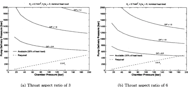
3.3.4 Maximum Pump Pressure 3.4 Feasible Specific Impulse Envelope
3.4.1 Dependence on throat aspect ratio 3.4.2 Throat Area . . .
3.4.3 Residence Time.
3.4.4 Material of Construction.
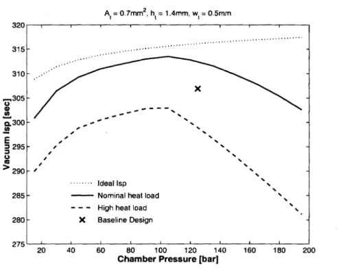
3.5 Baseline Design .
3.6 Summary of Feasibility Limitations . .
3.7 Application of model results to other propellants
4.1
3.8
4.3.3 Coolant Path
4.3.4 Coolant Passage Design General Considerations . . 4.3.5 Choice of Design Heat Transfer Coefficient Correlation. 4.3.6 Top Cooling Passage Design.
4.3.7 Side Cooling Passage Design 4.4 Thermo-Structural Design and Modeling .
4.3.2
4.4.1 4.4.2
Heat load . . .
Structural Design Choices . . . . . Cooling Passage Wall Thickness
85
86
89
9092
98
100 100 102 4.6 Ignition . . . 4.7 Conclusion4.4.3 Chamber wall thickness 4.4.4 Thermal modelling . 4.5 Injector Design . . . .
5 Fabrication and Packaging
5.1 Introduction . ..
5.2 Microfabrication Concepts . . 5.2.1 Photolithography . 5.2.2 Nested Masks . . 5.2.3 Deep Etching ..
5.3 Nozzle Etch Process Development .
5.4 Mask Creation .... 5.5 Fabrication 5.5.1 Wafer preparation
5.5.2
Cap Plates5.5.3
Wall Plates . . . . . 5.5.4 Nozzle Plates 5.6 Wafer Bonding 5.7 Cross Sections . 104 . . . 104 107 107 . . . 109 112 112 113 113 113. . . . .
114 114 116 117 120 126. . . . .
126127
129
131 133 135 Injector Spacing Injector Diameter. . . 4.5.1 4.5.25.11 Summary . . . . .
6.10 Experiment procedure overview.
6.5
Ignition . . . .6.11
Summary . 154 156156
157158
158
159159
159 162 163 138 141 144 144 . . . 144 145 147 147 • II . . . II 148 150 152 152 Propellant measurement and control6.3.1 6.8 System calibration . . . . . 6.8.1 Pressure transducers 6.8.2 Load cell . 6.8.3 Control Regulators . 6.9 Experimental Uncertainty
6.3.2 Oxygen pressurization system . 6.4 Coolant flow system
6.6 Data acquisition and control. . 6.7 Video monitoring and recording.
5.10.1 Overall process yield . . . 5.10.2 Quality of the glass seals . .
5.10 Further investigations and areas for improvement . 5.8 Packaging...
5.9 Process Development . .
6 Experimental Setup
6.1 Overview of Experimental Apparatus . . 6.2 Thrust stand and mounting plate . 6.3 Propellant flow system .
7 Experimental Results
7.1 Introduction . . . 7.2 Testing Overview. 7.3 Cold Flow Results
7.3.1 Static Pressure Test
7.3.2 Injector and Throat Area Characterization 7.3.3 Coolant Flow Characterization
7.4 Ignition Results . 165 165 165 . . .
167
167 168 171173
7.5 Initial Tests: Low Pressure 174
7.6 Water-cooled tests
176
7.6.1 Chamber Pressure and Thrust 180
7.6.2
Propellant Flow Rate 1807.6.3 Coolant .Pressures, Flow Rate, and Temperature
182
7.7
Summary .. 1888 Analysis and Discussion of Results 189
8.1
Introduction .189
8.2 Specific Impulse .
189
8.3 Heat Load. 190
8.4 Characteristic Exhaust Velocity, c*
196
8.5 Thrust Coefficient
198
8.6 Specific Impulse.
201
8.7
Summary201
9 Conclusions and Recommendations 205
9.1 Summary 205
9.2 Contributions . 206
9.3 Recommendations for Future Work 207
A Uncertainty Analysis 209
A.I Introduction.
209
A.2
Uncertainty of the Independent Measurements209
A.2.1
Pressure. 209A.2.2
Thrust. 210A.2.3 Mass Flow. 214
A.2.4
Temperature216
A.3 Uncertainty of the Derived Quantities 216
A.3.t Specific Impulse
217
A.3.2 Injector Diameter.
217
A.3.3 Throat Area 217
A.3.5 Thrust Coefficient Ao3.6 Heat Load 0 B Fabrication Details
B .1 Process Steps 0 •
B.2 Recipes used in the STS Etcher. 0 C Example CEA Input and Output Files
C.1 LOX/Ethanol Combustion 0 C.1.1 Input File. 0 Co102 Output File
Co2 Oxygen/Methane Combustion 0 0 C.2.1 Input File . 0
Co202 Output File 0
D Cold-side Heat Transfer Correlations Dol Nomenclature. D.2 Correlations . E Experimental Checklists Bibliography 219 219 221 221 221 227
227
227
. . . 228232
232
233 237237
237
241 245LIST
OF
FIGURES
2-1 Overall System Layout .
2-2 Extruded Chamber and Nozzle Shape 2-3 Possible Wafer Layouts .
2-4 Design wafer layout and terminology . . . . 2-5 Overall Model Flowchart .
2-6 Parameters defining chamber and nozzle shape . . . . . 2-7 Examples of scaled rocket shapes .
2-8 Lines of constant flow parameters . .
2-9 Vacuum Isp as function of Pc and OfF . . . . .
2-10 Hot-side heat transfer correlations . . . . 2-11 A simple model of the thrust chamber and cooling passage walls. 2-12 Two cross-sections with bond lines . . . . .
2-13 Dependence of T :Won chamber pressure . 2-14 Heat load vs chamber pressure .
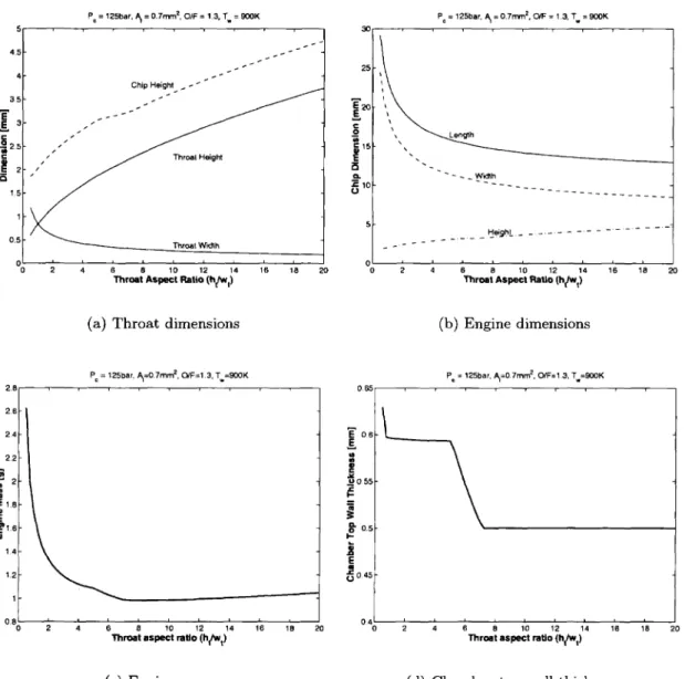
2-15 Throat Cooling Parameters vs. Chamber Pressure 2-16 Thrust to weight ratio vs throat aspect ratio 2-17 Size Parameters vs. Throat Aspect Ratio . . 2-18 Fabrication Parameters vs. Throat Aspect Ratio 2-19 Heat Load vs. Throat aspect ratio . .
2-20 Throat heat flux vs Throat area ratio
2-21 Throat Cooling Parameters vs. Throat Aspect Ratio .
3-1 Cold-side wall temperature vs. chamber pressure
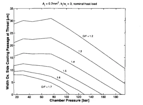
3-2 Cooling passage width vs. chamber pressure . 3-3 Final coolant temp vs. mixture ratio
3-4 Achievable vs required Pressure Rise .
3-5 Contours of output parameters illustrating feasible operating space.
26 27 28 28 30 33 34 36 36 39 41 43 46 47 48
49
50 51 5253
53 60 61 62 64 653-6 FeasibleIsp Envelope .
3-7 FeasibleIsp for various throat aspect ratios
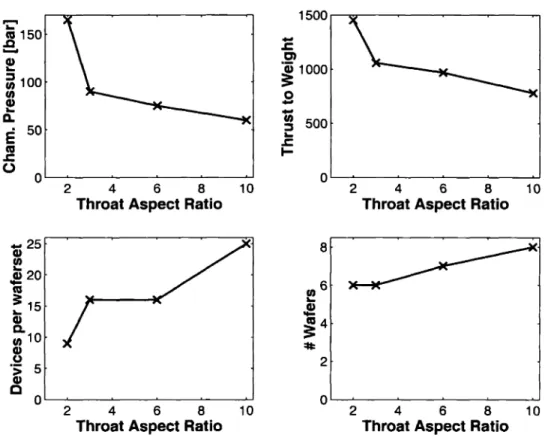
3-8 Performance and Fabrication Parameters
3-9 Isp envelope for various throat areas . . .
3-10 Performance and Fabrication Parameters
3-11 [sp envelope for differentreside~cetimes.
3-12 Isp envelope for SiC vs Si
3-13 Baseline Design Selection
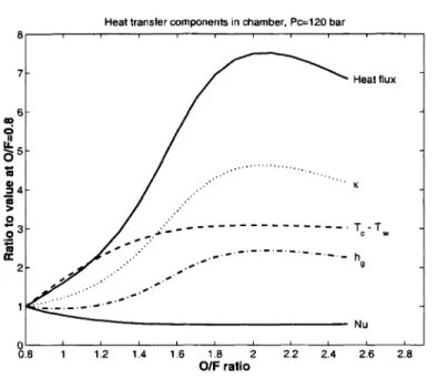
3-14 Factors affecting heat load as OjF increases.
4-1 Estimated local heat flux to the wall 4-2 Coolant Temperature Rise .
4-3 Coolant Path Selection. . .
4-4 Design Heat Transfer Correlation Selection
4-5 Top side cooling mask .
4-6 Typical cross sections of top cooling passages 4- 7 Top side cooling design. . . .
4-8 Nomenclature and Pin layout of top cooling passages. 4-9 Pin effective heat transfer
4-10 Top side cooling mask . . . 4-11 Side Cooling Passage Design. .
4-12 Wall Fillet FEM Calculation 4-13 Wall thickness and fillet radius 4-14 Tensile Stress in Chamber wall
4-15 Thermal calculation at throat cross-section 4-16 Thermal calculation of chamber cross-section 4-17 Cross Section of Injector Layout
4-18 Location of Injectors . 4-19 Specific Heat Ratio of Propellants 4-20 Injector design charts
5-1 Masking and etching process 5-2 Nested mask process . . . . .
66
67
68 7071
73 7576
8086
8788
91 93 94 95 9697
98 101 103. . . . .
103 105105
106 108109
110 111 . . . 114 1155-3 TMDE process . 5-4 Scalloping of sidewall during etching 5-5 Feature size dependence of nozzle etch
5-6 MIT-37 Nozzle Etch .
5-7 Nozzle Etch surface roughness. 5-8 Nozzle Etch . . . . 5-9 Mask 1: Top Holes
5-10 Mask 2: Top Shallow . . 5-11 Mask 3: Top Deep 5-12 Mask 4: Injectors . 5-13 Mask 5: Wall Cooling 5-14 Mask 6: Wall Interconnect. 5-15 Mask 7: Nozzle Nested . . 5-16 Mask 8: Centerline . . . 5-17 Mask 9: Bottom Holes . 5-18 All masks superimposed
5-19 Cap Plate (Note: the bottom cap plate would have a different front side without the 11 fluid ports) . . .
5-20 Top and Bottom Plate process 5-21 Wall Plate. . . .
5-22 Wall Plate process
5-23 Footing effect leads to depredation of the sidewalls. 5-24 Wall Plate damage during over-etch
5-25 Wall Plate damage reduced 5-26 Nozzle Plate. . . . . 5-27 Nozzle Plate process 5-28 Build 1 Bonding . .
5-29 Cross sections of completed die . . . . . 5-30 Cross section of completed die in flow direction 5-31 Schematic of rocket package . . . ~
5-32 Steps in glass sealing of rocket chip . .
5-33 Kovar tubes glass sealed to rocket chip . . . .
116 117 117 118 118 119 121 121 122 122 123 123 124 124 125 125 128 128 129 130
131
132 133 134134
135
136
137
138
139
1405-34 Fully packaged thrust chamber die 5-35 Wafer of packaging test dies . . . 5-36 Packaging Process Development. 5-37 Pressure testing of glass bead packaging
140
141
142
143
5-38 Cross section ofglass beads after sealing showing voids. . . . 145
5-39 Cross section of glass beads after sealing showing local silicon fracture 146
6-1 Overview of experimental apparatus
6-2
Views of thrust stand . 6-3 Mounting plate on thrust stand .6-4 Schematics of the oxygen and methane flow systems 6-5 Propellant supply system components
6-6 Oxygen gas booster pump . . . .
6-7 Schematic of the cooling flow system
6-8
Cooling flow system components . . . 6-9 Control signal for propellant supply 6-10 Pressure transducer calibration setup.6-11
Pressure transducer calibration . . . .6-12
Example of load cell calibration for thrust measurement6-13 Propellant supply pressure as a function of command signal. . .
7-1
Engine locations and die labels7-2
Static pressure test failure . 7-3 Example cold flow results7-4
Injector Diameter for Die C37-5 Throat area calculation for Die C3 ..
7-6
Coolant flow characterization . . . . . 7-7 Ignition results . . . .7-8
Images from Tests1
and2 .
7-9
Ignitor wires after first test7-10
Coolant flow and recorded thrust during first low pressure tests 7-11 Thrust produced by thermal expansion ofsupply tubes . . . . 7-12 Modifications to thrust stand to improve thrust measurement148
149
150
151
153153
155
155
157
158
160
161
161
166168
169
170171
172
174
175175
177
178
178
7-13 Images from water cooled tests, run 72 7-14 Images from water cooled tests, run 73 . 7-15 Images from water cooled tests, run 87 .
7-16 Chamber Pressure and Thrust for the water-cooled tests . 7-1 7 Propellant flow rates for the water-cooled tests . . . . . 7-18 Coolant flow, outlet pressure, and outlet temperature . . 7-19 Coolant flow, outlet pressure, and outlet temperature. 7-20 Closeup of coolant pressure and temperature, run 72 7-21 Closeup of coolant pressure and temperature, run 73
8-1 Comparison of inferred and predicted total heat load.
179 179 180 181 182 183 184 186 187 192
195
. . . 197 199 200 202211
212213
215
Comparison of experimental c* with calculationsMeasured Thrust coefficient . . . . 8-5
8-6
8-7 Ideal CF as a function of nozzle area ratio . . 8-8 Comparison of experimental and predicted Isp . . .
A-I Pressure Transducer Calibration 1 A-2 Pressure Transducer Calibration 2 A-3 Pressure Transducer Calibration 3 A-4 Thrust Stand Calibration . . . .
8-2 Difference between coolant outlet temperature and saturation temperature. 192 8-3 Predicted heat load for top and side passages if 30% of coolant flows through
top passages. . . 194 8-4 Predicted heat load for top and side passagesif45% of coolant flows through
LIST
OF TABLES
2.1 Material Properties of Silicon and Silicon Carbide . . .
3.1 Input Parameters for Baseline Design 3.2 Output Parameters for Baseline Design 2.3 Parameters used in chamber pressure study 2.4 Parameters for geometry study . . . . 2.2
4.1
5.1
6.1
Chamber and Nozzle parameters and baseline values
Nominal Heat Transfer Parameters
Masks used in Fabrication . . . . .
Summary of Experimental Uncertainty .
31
34 45 . . . 48 7478
89
120162
7.1 Water-cooled Test Summary. . . . 166
7.2 Coolant parameters for hot tests
167
7.3 Effective Injector Diameters . . .
170
A.I Example uncertainties in pressure measurements
210
A.2 Example uncertainties in injector diameters 218
A.3 Example uncertainties in throat area . . . 218
B.l Process steps for fabricating thrust chamber.
222
B.2 Recipe RKT-04
223
B.3 Recipe MIT-37 223 B.4 Recipe MIT-59 223B.5
Recipe TM-02 . . . 224 B.6 Recipe MIT-56 224B.7
Recipe MIT-51 224 B.8 Recipe SF6-4 . . .225
E.t Test Cell Preparation Checklist E.2 Gas Press.urization Checklist E.3 Hot or Cold Flow Run Checklist
242 243 244
NOMENCLATURE
Roman
A Area, usually a cross-sectional flow area
At Throat area D Diameter Dh Hydraulic diameter Isp Specific impulse L Length
L
c Chamber lengthLe Expansion nozzle length
L
* Characteristic chamber lengthF Thrust
M Mach number
P
Pressure, also perimeterQ
Total heat load (heat per unit time)R Gas constant
S Fractional uncertainty, also spacing between pins
T Temperature
Taw
Adiabatic wall temperature Tb Bulk fluid temperature Tbj Final bulk fluid temperatureTw Hot-side wall temperature
Twc Cold-side wall temperature
U Jet velocity
c c* 9 h meng m q u w We Wsp Wt
Effective exhaust velocity, F /
m
Characteristic exhaust velocity, PcAt/m Specific heat at constant pressure Specific heat at constant volume
Acceleration of gravity at Earth's surface.
Heat transfer coefficient, also height and specific enthalpy cold-side heat transfer coefficient
Hot-side heat transfer coefficient Throat height
Throat aspect ratio Length or span of a wall Mass of one engine Mass flow
N umber of side cooling passage layers Heat flux (heat per unit area per unit time) Corner radius of chamber
Converging radius of throat Diverging radius of throat
Wall thickness Velocity Width
Chamber width Nozzle exit width
Side passage width, usually minimum required
Non-dimensional groups
CF Thrust coefficient,
F/ (PeAt)
Nu Nusselt number, hL/~
OfF Oxidizer to fuel ratio, by mass, inox/mfuel
Pr Prantl number, J-LCp /~
Re
Reynolds number, puL /J-LT:W Thrust-to-weight ratio, F/rnengg
Greek
Q Thermal expansion coefficient
a* Passage aspect ratio
, Specific heat ratio (gas constant), cp /Cv
~ Change in a quantity
€ Nozzle expansion ratio, Ae/At
K, Thermal conductivity
J.L Viscosity
(}c Throat convergence angle
(}d Throat divergence angle
p Density
a Stress
amax Maximum allowable stress
Subscripts
c Chamber
e Exit
max Maximum
min Minimum
ref Reference condition
t
Throat, or totalSuperscripts
*
CharacteristicAcronYlllS
BOE
CVD MEMS RIE STS TMDEBuffered Oxide Etch (or Etchant) Chemical Vapor Deposition
Micro-Electro-Mechanical Systems Reactive Ion Etching
Surface Technology Systems Time-Multiplexed Deep Etching
CHAPTER
1
INTRODUCTION
1.1
Background and Motivation
In 1994, Epstein
[12]
initiated an effort at MIT to develop micro-fabricated gas turbine engines for propulsion and electric power applications. These engines are expected to be approximately 20 mm square by 4 mm deep, and produce useful power in the range of 10-50 W. Silicon carbide and silicon were identified as promising materials of construction for such a system for two main reasons. First, gas turbine engines require high speed rotating turbomachinery. The primary figure of merit used in selecting a material for such systems is the strength to density ratio, which is larger for both silicon and silicon carbide than it is for the high temperature super-alloys typically used in large scale gas turbine engines.* Second, high precision fabrication techniques exist to make the necessary parts from these materials, particularly in the case of silicon, which is used in most MEMS (Micro Electro Mechanical Systems) devices.The potential existence of high speed rotating gas turbines and compresso'rs at the millime-ter scale implies the application of this technology to of another kind of turbomachinery: turbopumps for very small liquid propellant rocket engines. Current rocket thrusters of this scale are blow-down or regulated systems that rely on pressurized propellant tanks to drive the propellants into the combustion chamber and provide the pressure there. This leads to a requirement for thick-walled tanks, which are much heavier per unit mass of propellant being stored than tanks of a typical liquid-fueled launch vehicle whose engines employ turbopumps to pressurize the propellant prior to its injection into the chamber.
*At 800 K, The specific yield stress is near 5 .104 m2/s2for Hastelloy X and Inconnel 600, but is about 1.5 . 105 m2/82 for silicon carbide, and 3.5 . 105 m2/s2 for silicon. [31]
If turbopumps could be added to the small rocket engines used on satellites, tank walls could be made thinner, resulting in a significant weight savings that could translate into a larger mass budget for payloads or additional fuel for a longer lifetime.t Additionally, because pumps allow for higher chamber pressures, the engines can be made smaller for the same thrust level, leading to additional weight savings. However, this weight savings is less significant, as the mass of the engines themselves tends to be a relatively small fraction of the total propulsion system weight.
This small size for a given thrust level implies another potential application of micfofab-ricated rocket engines, namely small launch vehicles. Their small size and high thrust to weight ratio could enable very small launch vehicles,
t
by providing the high performance and low mass necessary for orbital insertion at this small scale.On traditional liquid-fueled launch vehicles, the engines themselves tend to weigh about twice as much as the payload being delivered to orbit. At launch, they are required to produce a thrust slightly larger than the total weight of the vehicle. If they could produce this same thrust while weighing much less, this weight savings could be used to increase the size of the payload. There are two ways that the thrust-to-weight ratio can be increased for a given propellant combination. As was already mentioned, a higher chamber pressure will lead to a smaller engine for a given thrust level. Additionally, by simply making the engine smaller at a constant chamber pressure, the thrust to weight ratio will increase, everything else being equal. This is because the thrust produced is proportional to the throat area, while the weight of the engine is proportional to its volume. For perfect scaling the ratio of the throat area to the overall volume will increase as the rocket is made smaller. If one takes a traditional engine and makes four copies of it, each exactly half the size (one eighth the volume and one quarter the exit area) of the original, the four engines together would produce the same thrust as the larger original engine, but weigh only half as much. One could then do the same with the half-size engine, and make a total of 16 quarter-size engines, which when ganged together would still produce the same thrust as the original, but together only weigh a quarter of the original engine. In theory, this process could be
tlf one assumes that 30% of the satellite mass is fuel and that high pressure tanks weigh 10% of the fuel they contain, one would expect a total weight savings of around 2% of the satellite mass, or about a 6.5% increase in lifetime.
continued indefinitely, leading to a massively-parallel thrust system with a very high thrust to weight ratio.
As is often the case, reality and practicality get in the way of theory. This approach was used to varying degrees in the both the US and Soviet moon programs. The first stage of the Saturn V was powered by five F-l engines, saving about half the weight of an equivalent single engine according to the above argument. The Soviet launcher was to be powered by about 25 engines. By the arguments above, one would have expected that together they weighed about a fifth of an equivalent single engine. The rocket never had a successful flight as there were a number of single engine failures that led to failure of the launch system. A system with a large number of engines has the capability to provide redundancy in that the loss of thrust from one could have a small effect on total thrust level. However, if the failure of one engine can not be contained, additional engines will multiply the number of single point failure modes for the launch system, leading to a significantly reduced overall system reliability.
Other practical issues arise as well. One must justify the additional complexity required in the plumbing and control of many versus fewer engines. Additionally, the traditional view is that there is a minimum chamber residence time required for complete combustion in rocket engines, which does not scale with size.§ This means that one can not perform an exact scaling of engines without sacrificing efficiency, something launch vehicle designers are quite loathe do to.
Cost is another concern. Using traditional manufacturing methods, the cost of producing one half-size engine is probably not much less than the cost of producing a full-size engine, as in a perfect scaling each of the pieces would have to be reproduced at half-scale. The cost of a smaller engine might even exceed that of a larger one as it becomes harder to reproduce the detail of the original pieces at smaller and smaller scales. Eventually, limits in fabrication technology would prevent one from successfully making the smaller engine. In any case, the cost per unit thrust of an engine would certainly increase.
It is quite clear that the reduction in scale of rocket engines is not a so-called "silver-bullet,"
§This residence time is usually defined by L'"I the ratio of chamber volume to throat area, which is
typically between 80 and 300 em for large-scale rocket engines. [38]. The value ofL*for the thrust chamber tested in the present work is 6.5 em.
automatically leading to better system performance. As is usually the case, a high-level system tradeoff is required in choosing the appropriate number and size of engines for a given propulsion system.
Nevertheless, the concept of the microrocket engine has the potential to overcome a number of these drawbacks inherent in the reduction in scale of large liquid-fueled rocket engines. These issues will be discussed in the next section.
1.2
Potential of Microrocket Engines
1.2.1
Performance and Thrust to Weight Ratio
The above argument would imply that scaling down a large-scale rocket engine, such as the RD-120,' with a throat diameter of 185 mm to an engine with a characteristic throat dimension of 1 mm would imply a increase in the thrust-to-weight ratio, T :W, of 185 times, from about 75:1 to nearly 14,000:1. In fact, it is unlikely that such a direct scaling could be done, but the thrust chamber presented in this work should have a thrust to weight ratio of about 1250:1 at design. Operating at 10% of design chamber pressure, it has already demonstrated a T:W of 85:1.
A larger question is that of combustion, as it is the complete combustion of the propellants that allows rocket engine performance to approach ideal levels of specific impulse, a measure of fuel efficiency. As was mentioned in the previous chapter, the traditional view is that combustion processes do not scale to smaller sizes well. Essentially, this becomes an issue of residence time. If the time required for combustion to occur is smaller than the time" any given quantity of propellant resides in the chamber, the combustion will be incomplete, and the engine will suffer a performance penalty. The characteristic chamber length,
L
*,
is a measure of this residence time, so experience has shown that the required residence time in a rocket engine combustion chamber must be constant.If this were universally true, it would clearly indicate the infeasibility of microrocket en-gines. To further understand this effect, it is necessary to separate the combustion process
, An engine developed in Russia that develops approximately 850,000 N of thrust with kerosene and
into two parts. The first is the actual chemical reactions that convert the propellants into their reaction products, releasing the energy that increases their temperature and is then converted into directed kinetic energy by the expansion nozzle, producing thrust. The rates of these reaction are independent of scale, so if they are the limiting phase of the combustion process that set the minimum residence time, it would not be possible to effectively scale chemical rocket engines to the small scale. However, there is another factor to consider. In order for these reactions to take place, the fuel and oxidizer reactants must be in close prox-imity, and this is accomplished through injection and mixing in the chamber. In fact, this process typically occupies the majority of time a propellant element spends in a combustion chamber. This is a primarily fluid dynamic process, and it does scale. To first order, one may consider the mixing of two reactants as a diffusion process, which will take a shorter time to accomplish if the distance that each must diffuse is smaller. One would expect that this mixing length scale is on the order of the diameter or spacing of the propellant injectors. The use of microfabrication allows for very small injectors and injector spacings,1I which may imply that it is possible to reduce the injection and mixing time enough to allow for effective scaling of rocket engines to the millimeter scale.
It is difficult to analytically predict either the reaction rates or mixing times in rocket engine chambers. For this reason, an experimental approach has been taken in this work to explore the feasibility of scaling an engine to this scale. The initial results are quite promising, in that they imply that the reaction rate are not limiting the reaction, and that the mixing times are of the correct order to provide for complete combustion.
1.2.2
Cost
Another potential disadvantage for scaling rocket engines to mm-size is the cost of manu-facturing them. It is likely that manumanu-facturing a liquid cooled chemical rocket engine with a throat area on the order of 1 mm2 using traditional materials and techniques would be at least as costly as manufacturing an equivalently complex large scale one, though it is not clear this would even be possible. The introduction of silicon-based microfabrication techniques addresses this issue in two ways. First, it provides a technique that allows for
IIThe injector diameters of the thrust chamber tested in this work are 10-20 J.LffiJ and their spacing is
the very small (10 J.Lm) features required, and second, it does this in a way that allows for batch fabrication of these devices. Since the engines are manufactured many at a time from a set of wafers, the unit costs can be greatly reduced, particularly in large scale production. Though it is still very early to be certain, initial estimates of the manufacturing costs of such devices range from hundreds to thousands of dollars, which is of the same order per unit thrust as the cost of large-scale engines.
1.2.3
Modularity
Finally, microrocket engines present the potential advantage of modularity. If they are mass-produced and an effective way to package them is found, one could imagine a number of them combined into a "thrust pack" that produced a given quantity of thrust. If a design called for more or less thrust, these units could be removed or added to change the total thrust level. It is likely that this could add flexibility to the design process, as vehicles select the desired quantity of thrust, rather than having to design a vehicle around an already existing engine with a given amount of thrust.
1.3
Previous Work
It is believed that this work is the first example of a continuously operating, liquid-cooled, bipropellant rocket engine thrust chamber with a throat area that is less than 1 mm2.
Traditional engines in this thrust class typically decompose a hydrazine monopropellant, or use solid propellants, and have nozzles that are radiatively cooled. There is, however, a reasonable amount of related work, both in terms of "micropropulsion," often using silicon microfabrication techniques, and in terms of chemical combustion at these scales.
Janson [22] was one of the first to apply silicon batch fabrication techniques to micropropul-sian, using wet chemical etching techniques similar to those used in making ink-jet printer heads to create cold-gas thrusters.
Bayt [8] used the anisotropic deep reactive ion etching techniques reported by Ayon [3] (and also used in this work) to make smoothly-contoured nozzles, and demonstrated improved performance of cold gas thrusters. He also demonstrated an electrically augmented version
where the gas was heated prior to expansion.
Lewis [26] has proposed "digital micropropulsion," and demonstrated a number of single shot solid prope'llant rocket motors, batch manufactured from silicon, each of millimeter-scale.
As part of the MIT Microengine Project, Tzeng [41] demonstrated hydrogen combustion at the millimeter scale in a traditionally fabricated steel and quartz test rig, and then Mehra [31] demonstrated both hydrogen and hydrocarbon combustion in air at low pressure (up to 3 bar) at the millimeter scale inside microfabricated silicon combustors.
Finally, as part of the current research effort on microrocket engines at MIT, some addi-tional work has been performed. AI-Midani
[1]
investigated the feasibility of using elec-trically powered pumps to pressurize the propellants, and performed some studies of the fluid dynamics of the expansion nozzle design used in this work. He also investigated the kinetics of the oxygen-ethanol combustion, and simulated the start-up transient of a liquid oxygen-ethanol microrocket. Lopata [29] performed an experimental investigation of the cooling properties of supercritical ethanol at these scales by measuring the heat transfer capabilities of ethanol flowing through an electrically heated stainless steel capillary tube with an internal diameter of about 100 J.Lffi. More recently, Faust [13] improved Lopata's data reduction technique and extended the experiments to supercritical water. Most re-cently, Protz [35] has extended some of the work presented here and by AI-Midani to other storable non-cryogenic propellant combinations.1.4
Organization of
Thesis
This chapter has introduced the concept of a microrocket engine, and provided a preliminary indication of the potential benefits of such a system.
Chapter Two presents an overview of a conceptual microrocket engine system, and describes the set of models used to simulate the eventual performance of such a system.
In Chapter Three, these models are applied to engines using the oxygen/ethanol propellant combination in a study of their design space. The, primary physical constraints on design
are identified, and the concept of a feasible specific impulse envelope is introduced, which quantifies the maximum specific impulse that can be expected from an engine as a function of chamber pressure. The effects on the size and shape of this geometry are explored as engine geometry and material properties are varied. Finally, the baseline design for an oxygen/ethanol rocket engine is presented.
Chapter Four discusses the detailed design of a cooled thrust chamber conceived to demon-strate experimentally the viability of microrocket engines. Specifically, it is to be used to evaluate the feasibility of injection, mixing, and combustion of propellants in rocket engines of this scale manufactured from silicon. It is a liquid-cooled thrust chamber that runs on gaseous oxygen and methane. Its size and design mass flow are taken from the baseline design of Chapter Three, but the cooling system is specifically designed for the heat loads expected from this particular propellant combination.
Chapter Five presents the fabrication and packaging of this demonstration thrust chamber. Using silicon microfabrication techniques, it is manufactured, sixteen at a time, from six single-crystal wafers 100 mm in diameter. A fluidic packaging technique is developed to provide a connection for liquids and gases to the silicon device capable of operating at high pressure and temperature.
Chapter Six describes the experimental apparatus that was used to test the thrust chambers.
Chapter Seven presents the results of the experiments that have been performed with the fabricated thrust chambers. To date, there have been six successful ignitions, with a maxi-mum recorded thrust of about 1 N at a chamber pressure of 12.3 bar. This corresponds to 10% of the design chamber pressure, and a thrust to weight ratio of approximately 85:1.
Chapter Eight provides additional analysis and discussion of the results. The experimental data suggest that combustion is not being limited by incomplete reaction, as the combus-tion efficiency appears to be independent of pressure. Addicombus-tionally, it suggests that when corrected for chamber heat loss, and nozzle separation effects, the measured performance is within 5-15% of what would be expected from an ideal rocket engine.
Finally, Chapter Nine presents a summary of the research and presents recommendations for further work in this area.
CHAPTER
2
SYSTEM
DEFINITION AND MODELING
2.1
Introduction
The simple scaling arguments presented in the previous chapter suggest some significant advantages of microrocket engine technology. This chapter provides a definition of the mi-crorocket system and its subsystems and describes the set of models that has been employed to simulate the eventual performance of microrocket systems. In the following chapter, this model will first be used to illustrate the feasible design space for microrocket engines, and then to choose a baseline design within this feasible space.
2.2
Description of a Microrocket Engine Systelll
This section will provide an overview of a microrocket engine system. The complete system is illustrated conceptually in Figure 2-1. The three primary components of a microrocket system are the valves, the turbopumps, and the cooled thrust chamber. One could imagine combining these components in a number of different ways to create different rocket en-gine cycles, though the only cycle considered in this work is termed an expander cycle. In this type of cycle, the propellants would enter the chip through the valves at low pressure, and would then be pressurized by the turbopumps to the pressure required at the inlet to the cooling passages. The propellants next pass through the cooling jacket surrounding the chamber and nozzle to cool the thrust chamber walls to an allowable structural tem-perature, absorbing heat in the process. Some of this energy is then used to provide the original pressurization as the propellants pass through the turbopump turbines. Finally, the propellants are injected into the chamber where they mix and react to produce high
18mm
13.5 mm
"Figure 2-1: This figure illustrates a conceptual view of the location of the various system compo-nents. Illustration courtesy of Diana Park
temperature combustion products, which are expanded through the throat and exhaust nozzle to produce thrust.
The focus of this thesis is the cooled thrust chamber, and therefore is the primary basis of the model described in this chapter. The turbopumps are considered as well, but as it is determined that more than sufficient energy is available to drive them, only a very simplistic modeling effort is made. The valves are not discussed at all in this work, though an initial design study has been completed and a fabrication demonstration is in progress by Holke [21].
As was discussed in the previous chapter, the engine system will be constructed using sil-icon microfabrication techniques.
*
Current silicon fabrication technology requires that all features be two dimensional shapes that are formed in a wafer surface using deep reac-tive ion etching. This leads to a chamber and nozzle shape similar to that illustrated inStarboard
Port
Exit
Plane
Figure 2-2: Extruded Chamber and Nozzle Shape. The annotations show locations discussed in the thesis, as well as the nautical terms used to identify locations, defined relative to the throat location.
Figure 2-2, which is quite different from the axisymmetric chamber and nozzle shape used in most traditional rocket engines. This figure also illustrates the coordinate system and nomenclature used throughout this thesis to identify locations. The origin of the coordinate system is taken as the center of the throat, with the x-axis extending in the flow direction towards the aft end of the thrust chamber, and the y-axis extending towards the starboard side. The throat area, At, is defined by its height in the z-direction, ht , and by its width in the y-direction, wt,rather than being defined by a diameter.
2.3
Layout of thrust challlber
The modelling effort assumes an overall layout for the thrust chamber, so it is instructive to briefly explore why this layout was selected. In order to do this, one must consider how it is constructed from a number of wafer layers. Figure 2-3 illustrates a number of potential cross sections of a microrocket thrust chamber. Though the diagrams are schematics and not to scale, each view could be considered a section parallel to the y-axis through the combustion chamber near its forward end.
The simplest way to create the chamber and nozzle would be to etch the shape shown in Figure 2-2 into a wafer, and then cap it with another wafer, as shown in (a). This presents
- - - Bonding lines between wafers
(a) (b)
(c) (d)
(e) (f)
Figure 2-3: A sequence of cross sections (not to scale) illustrating the reasoning behind the generic wafer layout used in this work as shown in (f). The driving considerations are the need for cooling passages in close proximity to the chamber and nozzle, and the requirement that sharp corners be avoided at bond lines to prevent the high stress concentrations that would result at the corners from causing brittle failure in the silicon.
Cap Plate Wall Plate Nozzle Plate Wall Plate Cap Plate
Figure 2-4: Adding one or more nozzle plates to the wafer set increases the layers of side cooling passages, and can be used to increase the height of the chamber and nozzle. The labels show the terminology used to refer to the three kinds of wafers used in this work.
a problem in that it results in sharp corners where the top wafer is bonded to the lower wafer. This would lead to very high stress concentrations when the chamber is pressurized, and lead to fracture of the brittle silicon. A better design is to etch half of the nozzle into two identical wafers, and bond these to each other, as in (b). Cooling passages around the chamber and nozzle will be required to keep the walls from melting, and side cooling passages are easily added as part of the same nozzle etch, shown in (c). However, having cooling passages on the top and bottom surfaces of the chamber and nozzle requires adding wafers. The two wafers defining the chamber and nozzle could be made thinner, and top and bottom cooling passages then etched into two additional wafers, as shown in (d). This also allows injectors or pressure taps or ignitor ports to be etched into the chamber from the opposite side of the wafers that contain the nozzle etch, as in (e). However, it has the same problem as in (a), that of sharp corners in locations of high stress, though this time, in the cooling channel walls. The solution is to use a technique called nested masking that allows etches of different depths from the same side of the wafer, and make the top and bottom cooling passages span the bond line between the capping and nozzle wafers, as in
(f).
This is the general layout used throughout this thesis. Notice that the height of the cooling passages and the thickness of the top and bottom chamber walls can not vary across the wafer,t but that the thickness of the side walls of the nozzle can vary. The top and bottom wafers are termed cap plates, and the two wafers in the middle of Figure 2-3 are termed wall plates as they contain the top and bottom walls of the chamber and nozzle. Additionally, one could add one or more nozzle plates, as in Figure 2-4 to increase the number of layers of side cooling passages. The demonstration thrust chamber fabricated as part of this work has two of each kind of plate, or a total of six wafers.
2.4
Introduction to Overall
System
Model
This section will describe the overall model developed for a liquid oxygen/ethanol rocket engine system. The model takes a number of parameters describing an eventual engine,
tThis is not entirely true in the case of the top cooling passages, since the upper half of the etch can be eliminated, leaving passages approximately half as high. Though this leads to unwanted sharp corners, it is acceptable on the side of the passage away from the nozzle for areas of the passage with small widths.
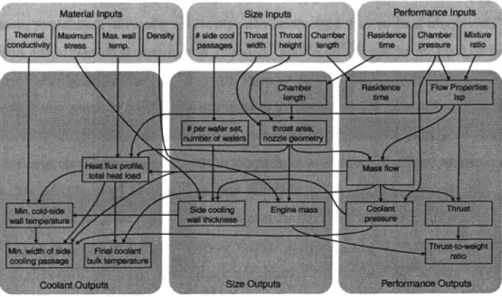
Figure 2-5: Flowchart of system model showing relationships between inputs and outputs.
and yields the important characteristics for determining the feasibility of that system. In addition to evaluating feasibility, it provides a number of performance and size related characteristics of the idealized system.
Figure 2-5 provides an illustration of the model's inputs and primary outputs, and traces the dependencies of those outputs. The next topics of this section discuss the inputs and outputs in more detail, and the following section discusses the sub-models that are used to calculate the various outputs of the model.
The model is implemented via a number of MATLAB routines, with essentially one routine per sub-model. A "master" routine distributes the inputs and coordinates the information flow between the various sub-models.
2.4.1 Model Inputs
The inputs to the model are selected to be those that one would need to choose in designing a microrocket engine. They can be divided into three categories: those related to the size and layout of the engine, those related to its performance, and those related to the material of construction.
Size Inputs: The two main size inputs are the width and height of the throat, Wt and ht . They determine the overall scale of the engine, and together with the pressure, effectively determine the mass flow and thrust. An optional size input is the length of the chamber, Lc . Either this or the residence time (see below) can be specified, and one determines the
other. The number of side cooling passages, nsp , a layoutpararneter, is also an input to the
model. However, it can also be calculated from ht by assuming an average wafer thickness.
Performance Inputs: The primary performance inputs are the chamber pressure,
Pc,
and the oxidizer to fuel mixture ratio,
OfF.
The expansion ratio of the nozzle, E, can bespecified as well, though it is held constant at 15 for the current study. Finally, as mentioned above, the residence time may be specified. As this affects performance, it is included here, but it is used primarily to determine the required length of the chamber.
Material Inputs: The parameters of the model that depend on the material of construc-tion are the maximum allowable wall temperature, Tw , as well as the thermal conductivity, K, the maximum allowable stress, O"rnax, and the density, p. The properties for the two materials considered are shown in Table 2.1.
Table 2.1: Material Propertiesof Silicon and Silicon Carbide. Based on information from [10, 28, 11].
Property Silicon Silicon Carbide
Tw 900 K 1400 K
K; 40 W1mK [800K] 63 W/mK [1000K]
p 2330 kg/m3 3200 kg/m3
O"max 1000 MPa 600 MPa
2.4.2
Model Outputs
The model outputs are those that a designer would consider in evaluating the usefulness of a given rocket system. They can be divided into categories similar to the inputs: size, performance, and cooling.
Size Outputs: The primary size outputs are the length, width, and height or thickness of the engine
(L,
W, andH).
Additionally, the mass of the engine, meng is returned, as well as the length of the chamber calculated from the desired residence time. Fabrication parameters such as the number of devices per wafer set, and number of wafers required are also considered size outputs. Critical wall thicknesses, such as that of the side cooling passage walls at the throat, and the required thickness of the chamber capping walls are also outputs.Performance Outputs: The performance outputs are the thrust,
F,
the mass flow, Tn,the specific impulse,
Isp(in
vacuum), the residence time, Tres ,the thrust-to-weight ratio, and the characteristic exhaust velocity, c*.+
Additionally, the physical properties of the nozzle flow are available.Cooling Outputs: The outputs relating to the cooling system include the heat flux profile to the wall, the integrated total heat load, and the maximum bulk temperature reached by the propellants while absorbing this load, Tbj. At the throat, the minimum required width of the side cooling passages, WsP, is estimated, and the coolant-side wall temperature,
T
wc ,at this location is calculated. As the actual functional dependence of the hot-side heat flux is not well known for the very high heat fluxes expected in microrockets, all of these parameters are calculated using both the nominal heat flux correlation used in the design of the demonstration thrust chamber and a correlation that results in a higher predicted heat load.
2.5
Description of Sub-Models
2.5.1
Parameterized rocket engine geometry
In order to simulate an eventual rocket engine system, it is necessary to have a parameterized geometry that can be scaled to consider engines of different size. Based on current micro-fabrication etching techniques, the engines are constrained to have a geometry produced
+The characteristic exhaust velocity, c*, is a measure of combustion temperature, and is defined as
4
~C
rcc Yn=Axn2+ Bxn+C 3"'"
2 we weYn
0L
c -1L
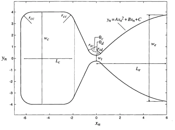
e -2 -3 -4 -6 -4 -2 0 2 4 6 XnFigure 2-6: The parameters used to define the chamber and nozzle geometry. The baseline shape is pictured, with scale in mm.
byetching of two-dimensional features into wafer surfaces. An example of this is shown in Figure 2-2, an illustration of the chamber and nozzle section of the eventual demonstration microrocket. This shape is then parameterized to provide for a variety of rocket sizes.
The primary parameters of importance are the throat width and height which control the mass flow for a given chamber pressure; the chamber length which controls the combustion residence time; and the expansion ratio of the nozzle which impacts specific impulse and surface area of the expansion section of the nozzle. The full parameterization of the two dimensional rocket shape is presented in Figure 2-6. This shape is then extruded upwards bythe throat height.
Table 2.2 presents the values of each parameter for the baseline geometry of the demonstra-tion thrust chamber.
In the scaling study presented later in this chapter, the independent geometrical parameters are Wt, ht , Le . The other lengths and nozzle expansion profile are all scaled proportionally
Table 2.2: Chamber and Nozzle parameters and baseline values
Symbol Description Value Symbol Description Value
Wt Throat width 0.5mm Ttc Converging throat radius 0.75 mm
ht Throat height 1.5 mm Ttd. Diverging throat radius 0.5 mm
We Chamber width 8mm Tee Chamber corner radius 1mm
We Exit width 7.5mm ()c Chamber convergence angle 65 deg
L
c Chamber length 4.5mm (}d Throat divergence angle 45 degL
e Expansion length 6mm 15 10 5 0)(
-5 -10 -15 -15 -10 -5 0 5 10 15Figure 2-7: Examples of scaled nozzle shapes. Scale in mID. Top: Wt
=
0.5 mm, Lc == 9 mm;Middle: Wt
=
0.25 mm, Lc == 9 mm; Bottom: Wt ==0.75 mm, Lc==5 mm.to Wt, and the two angles are held constant. This allows the different nozzle flows to have the same Mach number in equivalent locations. Three examples of a scaled geometry are presented in Figure 2-7.
2.5.2
Rocket Performance and Mass Flow
The primary measure of performance for a rocket engine is its specific impulse, orIsp . In this
chapter and in Chapter 3, the specific impulse in vaCUUlll is used in comparisons between different engine systems. The other performance metric considered is the thrust-to-weight ratio. Again, the vacuum thrust is used in this ratio. For a given chamber pressure and
propellant mixture ratio, the Isp and other flow properties are determined using CEA, a
NASA code developed by Gordon and McBride [16J. It has a rocket performance module that allows for adiabatic equilibrium and frozen calculations of rocket flow properties as a function of chamber pressure, propellant mixture Tatio, and area ratio.
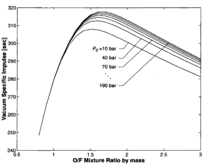
Rather than perform a new CEA run for each chamber pressure and mixture ratio consid-ered, a large matrix of these runs are pre-computed and combined into a rocket performance database. For the ethanol/oxygen scaling study presented here, the chamber pressures con-sidered are 10, 20, 30, ... , 200 bar, and the oxidizer to fuel mass ratios are 0.8, 0.9, ... , 3.0. The total number of runs in this performance database is then 460. From this matrix, a two-dimension linear interpolation predicts the performance parameters for any interme-diate pressures or mixture ratios required by the model.
All of the calculations performed assume equilibrium chemistry up to the throat, and frozen chemistry in the expansion nozzle. Flow conditions are calculated at subsonic area ratios of 16 (the chamber), 13, 10, 5, and 2. Downstream of the throat, conditions are calculated at area ratios of 1 (the throat), 2, 3, 4, 6, 8, 10, 12, and 15 (the nominal exit plane). The flow properties at these discrete area ratios are then interpolated onto locations in the nozzle corresponding to locations of equivalent effective area ratio. This effective area ratio is based on an effective through-flow width, illustrated by the dashed lines perpendicular to the flow direction in Figure 2-8. Examples of the input and output files for a CEA run are presented in Appendix C. Figure 2-9 shows the vacuum Isp for the full range of mixture
ratios considered for a number of chamber pressures between 10 ~nd 200 bar.
The results of these calculations are idealized in the sense that they are adiabatic, assume the combustion reactions proceed completely to equilibrium, and do not account for friction effects on the chamber and nozzle walls. The variation in Isp with pressure is therefore due
only to the effect of pressure on the equilibrium composition, and not due to its potential impact on the kinetic rates of the combustion reactions. For these reasons, one would expect the eventual performance of a microrocket engine to be lower than the values presented here. Nevertheless, this idealized model will prove valuable in identifying the feasible design space and" upper performance limits of micro rocket engines.
Figure 2-8: The dotted lines perpendicular to the flow direction show the surfaces of constant flow conditions used in the model.
190 bar Pc=10bar 40 bar 70 bar -310 320.---,---~---r---~---...., 250 i300 a!!. Q) UJ '3290 C. .5 ~280 ·u
8-en270 E :J :J u260 ~ 3 2.5 1.5 2O/F Mixture Ratiobymass
240 ""'---- - . L --L.. ....L...- ""'---- - 1
0.5
Figure 2-9: VacuumIsp for oxygen/ethanol combustionasafunction of mixture ratio for anumber
2.5.3
Combustion Residence Time and Chamber Length
The chamber residence time is an important parameter considered in the design of micro rocket engines. It is defined as:
Pc~
Tres
=
-.-m (2.1)
and corresponds to the average time a particle spends in the combustion chamber. It is worth noting that for a choked nozzle flow, both Pc and
m
are directly proportional toPc,
so the residence time is independent of pressure. When calculating the chamber volume, ~,
the chamber is considered that area of the rocket forward (towards negative y-direction) of the dotted line in Figure 2-6. Thus, if the chamber density is known from the flow properties output by the CEA performance simulation discussed above, the chamber length can be written as a function of residence time:
L
e =~
(mTres
h+
(4 _ 1r)Tee2)
We Pc t
(2.2)
This allows for either the chamber length or residence time to be considered the independent variable in the sizing model.
2.5.4
Wall Heat load
The heat load to the wall is estimated by utilizing a heat transfer coefficient, where the heat flux to the wall,
q,
is considered proportional to the difference between the adiabatic wall temperature,Taw,
and the actual wall temperature,T
w .(2.3)
The hot side gas heat transfer coefficient, hg, is generally obtained from empirical correla-tions. Hill and Peterson[20] suggest three correlations for rocket engine nozzles that are used in this work. These correlations are generally given in terms of non-dimensional parame-ters, with the Nusselt number, Nu, being the parameter that describes the heat transfercoefficient:
Nu = hgL K
(2.4)
The first of these correlations, originally based on fully developed turbulent pipe flow, is:
(2.5)
where for the case of the rectangular cross section of the MicroRocket Thrust Chamber, both Nu and Re are based on Dl' a so-called "laminar" diameter, proposed in [23] to improve the accuracy of turbulent heat transfer correlations in rectangular channels.
(2 11 *(
*))
Dl ~ Dh -
+
- Q 2 - Q 3 24where Dh is the hydraulic diameter, 4A/ P, and a* is the aspect ratio of the channel.
(2.6)
The second correlation is suggested for use in the supersonic part of the nozzle and is quite similar to that presented above. In this case, Nu and Re are based onL,the "axial" distance downstream from the throat. Here,
(2.7)
where a has a value of approximately 0.025 to 0.028.
For both of these correlations, a decision must be made as to what temperature is used for determining the fluid properties used in the non-dimensional parameters. One option is to use the local static, or bulk temperature, but the traditional choice is to use a film temperature, Tf . Hill and Peterson [20] suggest defining this as Tf = Tw
+
O.23(Tg - Tw )+
0.19(Taw - Tw ) for the supersonic portion of the nozzle, and as Tf
=
(Tw+
Tg)/2 for the chamber and subsonic portion of the nozzle. Both Tf and T were considered, but as can be seen in Figure 2-10, Tf predicts a significantly lower heat flux. Though this would be desirable, the bulk temperature is used to evaluate properties in this work, as it provides a more conservative estimate, given the large uncertainties in predicting rocket heat fluxes.Pc=125bar, hi=1.4mm,WI=0.5mm, OIF=1.3, T w= 900K 300r---r----~---...---....,....---r---, 6 -"-·-'_1_. 4 Eqn 2.7 -2 0 2 Nozzle x-position [mm] -4 Eqn 2.5 - Bulk Temp Properties - - , Film Temp Properties (,
I
,
,
,
r,
r,
Eqn2.8~!,
OL...-_ _---.L... ---L...- L . - -_ _----I.. ...."I..-_ _- - - - J -6 ~250
~
=200 as::
.s
>c ~150 iL fti Q) ~ 'C100 .!! as .5 u; w 50Figure 2-10: The various correlations considered for hot-side heat transfer estimation. The two used in the design are Equation 2.5 with properties evaluated at the bulk temperature (called the nominal heat flux case), and Equation 2.8 (called the high heat flux case).
The third correlation is originally due to Bartz [9] , and can be written as:
h = [ 0.026
(J-l
0.2
cp )(pc)O.8
(Dt)O.l] (At)O.9
a9 (Dt)O.2 PrO.6 c c* Tt A (2.8)
where the subscript c refers to chamber or stagnation conditions, and tto throat conditions. Tt is the radius of curvature of the nozzle wall at the throat, and a is defined as
1
(j=---~~~---~-=--[
~¥:
(
1+
1~1)
M2+!
]
0.8-0.
2w (1+
12
1)
M2 O.2w(2.9)
where w is the exponent in a power-law viscosity-temperature relationship. (J-L ex
TW)
The flow properties provided by the CEA calculation are used to evaluate the local Re and Pr required by the above correlations to produce the estimated hg . This along with the
flow temperature and the input wall temperature determine the heat flux profile, shown in Figure 2-10. Given the large variation in predicted heat fluxes, two cases are considered in the model: a "nominal" case predicted using Equation 2.5 with bulk temperature properties, and a 'high" heat flux case, predicted using Equation 2.8.