In this study, we present the development and the characterization of a generic platform for cell culture able to monitor extracellular ionic activities (K+, NH4+) for real-time monitoring of cell-based responses, such as necrosis, apoptosis, or differentiation. The platform for cell culture is equipped with an array of 16 silicon nitride micropipet-based ion-selective microelectrodes with a diameter of either 2 or 6 µm. This array is located at the bottom of a 200-µm-wide and 350-µm-deep microwell where the cells are cultured. The characterization of the ion-selective microelectrode arrays in different standard and physi-ological solutions is presented. Near-Nernstian slopes were obtained for potassium- (58.6 ( 0.8 mV/pK, n ) 15) and ammonium-selective microelectrodes (59.4 ( 3.9 mV/pNH4, n ) 13). The calibration curves were highly reproducible and showed an average drift of 4.4 ( 2.3 mV/h (n ) 10). Long-term behavior and response after immersion in physiological solutions are also pre-sented. The lifetime of the sensors was found to be extremely long with a high recovery rate.
Measurement of different ion concentrations in cell cultures is of central importance for understanding cellular signaling and cell metabolism. Among analytical methods available for investi-gating extra- and intracellular ionic fluxes, ion-selective electrodes (ISEs) and fluorescence-based techniques are the most common ones. The first measurements of intra- and extracellular ionic concentrations performed using glass-capillary ISEs date back to the mid 1970s.1-4Later on, supported by a rapid development of highly efficient fluorophores for many ions of interest, the ISE
methodology has been surpassed by fluorescence techniques.5 The reasons are mainly experimentalstedious and difficult to control preparation of ISE glass micropipets and impracticality of performing parallel measurements on a number of cells in the culture. Yet, cellular measurements with ISEs, which allow assessing free ion activities (contrary to fluorescence where total ion concentrationsare measured), constitute an interesting meth-odology complementary to the fluorescence techniques. Further-more, it is an only alternative for applications where fluorophores are not available, such as for the monitoring of the urea cycle for recording the concentration of NH4+.
To realize microelectrode arrays of various geometries and functionalities, microfabrication technology is the obvious choice. In cell biology, microfabricated devices are already largely exploited for investigating cell network electrophysiology and applied in other cell-based assays.6In comparison, the develop-ment of ISE arrays is far less advanced. In their pioneering work, Buck et al. used a Kapton-based K+- and pH-sensitive micro-electrode array for in vivo monitoring of a beating heart during induced ischemia.7,8Other microfabricated arrays of ISEs have been developed for the detection of blood electrolytes.9-13To monitor the ionic concentration at the cellular level, the dimen-sions of the ISEs should ideally have cellular or subcellular sizes and the sensors should be organized in a dense array able to record ionic fluxes of neighboring cells. Therefore, localized ion concentration change in a closer area around an electrode could be detected in response, for example, to local drug delivery. The
* To whom correspondence should be addressed. E-mail: olivier.guenat@ unine.ch.
†Harvard Medical School. ‡University of Neuchaˆtel.
(1) Khuri, R. N.; Agulian, S. K.; Hajjar, J. J. J. Appl. Physiol. 1972, 32, 419-422.
(2) Purves, R. D. Microelectrodes Methods for Intracellular Recording and
Ionophoresis; Academic Press: London, 1981.
(3) Ammann, D. Ion-selective Microelectrodes, Principles, Design and Applications; Springer-Verlag: Berlin, 1986.
(4) Fry, C. H.; Langley, S. E. M. Ion-selective electrodes for biological systems; Hardwood Academic Publishers: Amsterdam, 2001.
Development
of an Array of Ion-Selective Microelectrodes
Aimed
for the Monitoring of Extracellular Ionic Activities
Olivier T. Guenat,*,† Silvia Generelli,‡ Nicolaas F. de Rooij,‡ Milena Koudelka-Hep,‡ Franc¸ ois Berthiaume,† and Martin L. Yarmush†
CenterforEngineeringinMedicine,MassachusettsGeneralHospital,HarvardMedicalSchool,Boston,Massachusetts02114 SAMLAB,InstituteofMicrotechnology,UniversityofNeuchaˆtel,2002Neuchaˆtel,Switzerland
(5) Voipio, J.; Pasternack, M.; Macleod, K. In Microelectrode Techniques: The
Plymouth Workshop Handbook, 2nd ed.; Ogden, D. C., Ed.; Company of
Biologists: Cambridge, UK. 1994; Chapter 11.
(6) BioMEMS; Urban, G. E., Ed.; Springer: Dordrecht, The Netherlands, 2006. (7) Cosofret, V.; Erdo¨sy, M.; Johnson, T. A.; Buck, R. P.; Ash, R. B.; Neuman,
M. R. Anal. Chem. 1995, 67, 1647-1653.
(8) Lindner, E.; Buck, R. Anal. Chem. 2000, 72, 336A-345A.
(9) Uhlig, A.; Lindner, E.; Teutloff, C.; Schnakenberg, U.; Hintsche, R. Anal.
Chem. 1997, 69, 4032-4038.
(10) Yoon, H. J.; Shin, J. H.; Lee, S. D.; Nam, H.; Cha, G. S.; Strong, T. D.; Brown, R. B. Sens. Actuators, B 2000; 64, 8-14.
(11) Scheipers, A.; Wassmus, O.; Sundermeier, C.; Eshold, J.; Weiss, Th.; Gitter, M.; Ross, B.; Knoll, M. Anal. Chim. Acta 2001, 439, 29-38.
(12) Zhu, J.; Zhu, Z.; Lai, Z.; Wang, R.; Wu, X.; Zhang, G.; Zhang, Z. Sens. Mater.
2002, 14, 209-218.
(13) Gyurcsanyi, R. E.; Rangisetty, N.; Clifton, S.; Pendley, B.; Lindner, E. Talanta
2004, 63, 89-99.
1
Published in Analytical Chemistry 78, issue 21, pp. 7453–7460, 2006, which should be used for any reference to this work
microfabricated sensors mentioned above are much larger than cell dimensions and are therefore not well suited for this purpose. The approach presented in this paper is a step in this direction. Recently, we reported the development of arrays of micro-fabricated silicon nitride micropipets with diameters ranging between 200 nm and a few micrometers.14These micropipets were integrated on a cell culture platform and were filled with ion-selective cocktail by means of microchannels to form ion-ion-selective microelectrodes. The microfabrication of this platform equipped with an array of 24 micropipets whose dimensions were 6 µm in diameter and 50 µm in length, as well as the results of preliminary tests with a Ca2+-selective membrane, are described in a previous paper.15 It is also shown that the micropipet geometry allows achieving a reproducible and clearly defined membrane thickness and active surface as well as ensuring good mechanical anchoring of the membrane. Furthermore, the volume of ion-selective membrane contained in the microchannel connecting the micro-pipet constitutes a large reservoir for plasticizer, carrier, and ionic sites that increases the sensor lifetime (Figure 1).
In this study, we extend our research by developing a generic platform for real-time monitoring of extracellular ionic activi-ties (K+, NH
4+) of cell-based responses, such as necrosis and apoptosis, differentiation, etc. Potassium, which is present at high levels in intact viable cells, leaks out of dying cells; elevated extracellular potassium ranging between 1 and 150 mM K+can be used as a marker of cell death. Ammonium is taken up by differentiated hepatocytes, and a decrease in extracellular NH4+ 16 from 1 mM to 10 µM can be used as a marker of stem cell differentiation into hepatocytes. Another particular interest in NH4+ sensors arises from the fact that this analyte is the product of many enzymatically catalyzed reactions. The new platform is equipped with an array of 16 ion-selective microelectrodes located at the bottom of a microchannel where the cells will be cultured (Figure 2). The length of the microelectrodes is 30 µm, with diameters of either 2 or 6 µm. The analytical characteristics of the ISE array with different potassium and ammonium membrane formulations are compared on the basis of the sensitivity, selectiv-ity, stabilselectiv-ity, and reproducibility of the measurements and lifetime of the microelectrodes.
EXPERIMENTAL SECTION
Design and Fabrication of the Ion-Selective Microelec-trodes Array. The array of 16 ion-selective microelecMicroelec-trodes is integrated at the bottom of a cell culture platform that comprises a 200-µm-wide and 365-µm-deep microwell where the cells are cultured (Figure 2). The microwell widens on both ends to form circular cavities (1 mm in diameter) intended for medium perfusion and cell seeding. A network of smaller microchannels, connected to the microwell, aims to deliver and modulate the hormone/growth factor environment in the cell culture, through holes located at the other extremity of these channels. The backbone of the ISE array consists of an array of silicon nitride micropipets structured in a silicon substrate, arranged in two rows of eight and separated by 150 µm. Each micropipet is connected to a 50-µm-wide and 20-µm-deep microchannel etched in a Pyrex substrate that is aligned and bonded to the silicon substrate. The micropipets are filled with ion-selective cocktails via the micro-channels by capillary forces (Figure 1).
The micropipets arrays are fabricated using extensions of previously reported microfabrication technologies.14,15Briefly, an array of either 2 or 6 µm in diameter and 30-µm-deep holes is etched by deep reactive ion etching (DRIE) in a (100) silicon wafer. Then, a thermal silicon dioxide layer and a silicon nitride layer are successively deposited. The thickness of the oxide layer, which is used as a sacrificial layer, allows for the reduction of the hole diameter, and thus the precise definition of the final diameter of the micropipet, whereas the thickness of the silicon nitride layer defines the wall thickness of the micropipets. The wafer topside is then locally etched by a second DRIE until the micropipet tips are exposed. The oxide tips are then removed in buffered HF, while the nitride caps of the tips are etched by RIE, using a SF6 gas mixture. A thin oxide layer is deposited onto the topside silicon surface as an electrical insulation. A Ta/Pt layer is then deposited on the wafer backside and structured by a liftoff technique, to create the internal electrodes of the ISEs. In parallel, a Pyrex substrate is etched in 20% HF to structure the microchannels that connect the micropipets. Each microchannel is equipped with 1 mm in diameter through holes, for the individual filling of the micropipets. After dicing, the silicon and Pyrex chips are anodi-cally bonded. The dimensions of the silicon chip are 20× 18 mm2, whereas the Pyrex chips are slightly smaller (15 × 15 mm2), allowing the metallic pads located at the bottom of the silicon chip to be contacted by wire bonding. The size of the active surface of the ion-selective membrane at the top of a 2- and a 6-µm-diameter micropipet is about 3 and 28 µm2, respectively.
Prior to filling the micropipets with the ion-selective cocktail, the device was dehydrated at 150°C in a convection oven for 24 h and then silanized. A vapor-phase silanization was carried out by using N,N-dimethyltrimethylsilylamine during 60 min at 150
°C. This silanizing agent is toxic and corrosive and was handled appropriately in a fume hood. Filling of the micropipets was typically carried out by dispensing 0.7 µL of ion-selective cocktail into each microchannel (Figure 1). Due to capillary forces, the membrane cocktail flows through the microchannel and fills the micropipet. If air bubbles were present in the microchannels, the chip was placed in a vacuum chamber for 5 min at 50 kPa, to remove them. Two days were allowed for the evaporation of the solvent (cyclohexanone).
(14) Guenat, O. T.; Generelli, S.; Dadras, M.; Berdondini, L.; de Rooij, N. F.; Koudelka-Hep, M. J. Micromech. Microeng. 2005, 15, 2372-2378. (15) Guenat, O. T.; Dufour, J.-F.; van der Wal, P.; Morf, W.; de Rooij, N. F.;
Koudelka-Hep, M. Sens. Actuators, B 2005, 105, 65-73. (16) Boon, L.; Meijer, A. J. Eur. J. Biochem. 1988, 172, 465-469.
Figure 1. Cross section of two ion-selective microelectrodes integrated in the platform. The ion-selective cocktail is introduced in the micropipets from the backside of the chip, via a microchannel network. For the sake of clarity, the SiO2sacrificial layer is not shown,
Reagents. The ionophores (valinomycin, nonactin), the ionic additives (potassium tetrakis[3,5-bis(trifluoromethyl)phenyl]borate (KTFPB) and sodium tetrakis[3,5-bis(trifluoromethyl)phenyl]-borate (NaTFPB)), the membrane matrix high molecular weight poly(vinyl chloride) (PVC), the plasticizers bis(2-ethylhexyl) sebacate (DOS), 2-nitrophenyl octyl ether (NPOE), and the cyclohexanone were of Selectophore quality from Sigma-Aldrich (Fluka), whereas the salts were of puriss p.a. quality from the same company. The silanizing agent N,N-dimethyltrimethylsilyl-amine (purum) was also purchased from Sigma-Aldrich (Fluka).
D-(+)-Glucose anhydrous, MgSO4anhydrous (ReagentPlus), and CaCl2dihydrate were from Sigma-Aldrich. Ammonium standard solution (0.1 M) was from Thermo Orion (Beverly, MA). Aqueous solutions were prepared with freshly distilled deionized water (18 MΩ‚cm specific resistance). Phosphate buffer solution (PBS) was prepared with analytical grade salts from Sigma-Aldrich, whereas Dulbecco’s modified Eagle medium (DMEM), fetal bovine serum (FBS), and penicillin-streptomycin (PS) were all purchased from Invitrogen Corp.
Membrane and ISEs. Five selective compositions were examined in this study, membranes A and B for K+-ISEs, and membranes C, D and E for NH4+-ISEs. The formulations are given in weight percent:(A) valinomycin (5.0), KTFPB (1.0), DOS (89.0), PVC (5.0); (B) valinomycin (5.0), KTFPB (1.0), DOS (84.0), PVC (10.0); (C) nonactin (5.0), KTFPB (1.0), DOS (89.0), PVC (5.0); (D) nonactin (5.0), NaTFPB (0.6), DOS (89.4), PVC (5.0); (E) nonactin (5.0), NaTFPB (1), NPOE (89.0), PVC (5.0).
The components of each membrane (totaling 200 mg) were dissolved in cyclohexanone (420 µL). Cyclohexanone was pre-ferred to tetrahydrofuran, which is generally used for microelec-trode applications, since it has a lower evaporation rate and is therefore better suited for filling the microchannels. The ISEs were conditioned in 1 mM chloride solution of the primary ion for at least 1 day.
Experimental Equipment and EMF Measurements. All solutions used for measurements were obtained by successive dilution of stock solutions. Potassium stock solution (0.2 M KCl) was prepared by dissolving appropriate amounts of KCl in deionized water, whereas a commercially available 0.1 M am-monium stock solution was used. A high glucose medium solution (HGMS) with an approximate osmolarity of 300 mOsM was prepared for ammonium measurements. It was composed of 297 mMD-glucose, 1.8 mM CaCl2, and 0.8 mM MgSO4. The concen-trations of calcium chloride and magnesium sulfate in HGMS were
similar to those in DMEM. Physiological solutions were made of DMEM, mixed with 1, 5, or 10% of FBS, and 1% penicillin-streptomycin.
Screening of the electrodes was performed by determining the slope of the calibration curve (EMF versus log aKor log aNH4) by
exposing the ISE array to KCl or NH4Cl standard solutions with incremented concentrations. Unless otherwise specified, the slopes of the potassium and ammonium calibration curves were calcu-lated in the concentration range between 10-4and 0.1 M KCl and between 10-5and 10-2M NH4Cl, respectively. For the calculation of activity coefficients, the Debye-Hu¨ckel theory was used. The selectivity coefficients for Na+and K+were determined by the fixed interference method (FIM)17with a background level of 150 and 5.5 mM chloride solution, respectively. Comparative mea-surements of the ammonium samples were performed with an Orion ammonium electrode (ammonium sensing module 931801, Thermo Electron Corp., Beverly, MA). Up to 16 microelectrodes were tested simultaneously using a 16-channel homemade high-impedance input (1014Ω) amplifier, connected to a PC and a data acquisition card (DAQCard 6024E, National Instruments) in combination with Labview 7.0 software. A low-pass filter stage with a cutoff frequency of 10 Hz was integrated to the amplifier. The chips were placed in a PMMA flow-through cell (Figure 3) that integrated a minireference electrode (mini-Ag/AgCl/3 M KCl DRIREF-2, World Precision Instruments, Stevenage, UK), located downstream. The volume of the flow-through cell was∼15 µL. The flow-through cell and the amplifier were placed in a Faraday cage in order to avoid external EMF perturbations and light interferences.18
(17) Umezawa, Y.; Bu¨hlmann, P.; Umezawa, K.; Tohda, K.; Amemya, S. Pure
Figure 3. Platform with the ISE array incorporated in a flow-through manifold with the reference electrode (RE) located downstream. Each microelectrode is connected to a high-impedance input amplifier (E1,
E2,...).
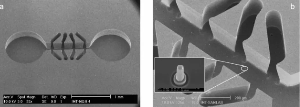
Figure 2. SEM pictures of the platform for extracellular ionic measurement. (a) Overall view of the main microchannel that widens on both ends in two holes. Microchannels for drug delivery are adjacent to the main channel. (b) The array of ion-selective microelectrodes is located at the bottom of the 200-µm-wide and 365-µm-deep main microchannel. Inset: closeup of a silicon nitride micropipet with a 2-µm diameter.
Lifetime measurements were performed under continuous-flow measurement by pumping two samples of different concentrations at regular frequency. The permutation was triggered by an electrostatic relay (Finder, Distrelec AG) connected to a two-way pinch valve (P/N 075 P3MP12-233, BioChem Valve Inc.), placed ahead of the peristaltic pump (Masterflex 7519-20, Cole-Parmer). On the other hand, calibration curve determinations were carried out under stopped-flow conditions. Due to the complex geo-metrical shape of the microchannel network, the following procedure was experimentally chosen in order to prevent sample contamination with the remaining solution that was measured beforehand and thus to guarantee a good reproducibility of the measurement conditions. First, 0.5 mL of deionized water was flushed through the system at a flow rate of 12.6 µL/s in order to clear the device of any remaining preconditioning solution. Then, 2 mL of sample solution was delivered in the flow-through cell in the following sequence at the same flow rate: pump 1 mL, wait 20 s, pump 0.5 mL, wait 20 s, and pump 0.5 mL. Subsequently, a stabilization time (7 s) was allowed and the EMF potential was then recorded. The potential data values recorded were the mean values of the last 500 points, collected within a 5-s time period. The stability of the potential data values recorded during this period was excellent, with standard deviations in the range of 0.05% or lower.
To keep most of experimental conditions constant, the flow rate of 12.6 µL/ used for the characterization of the system was also used in preliminary cell culture tests. This relatively high flow rate is clearly not well adapted for the cell cultures; therefore, in future work it will be decreased to a few microliters per second. It must be noted that despite the relative large sample volume used for the characterization of the platform, the small volume of the microwell is appropriate for the localized detection of in situ ionic secretion or uptake of cells. Thus, the array of microelec-trodes will make it possible to record in real time and in parallel the cellular response to local drug delivery through the side channels.
All measurements were carried out at room temperature at 25 ( 3°C. The recorded temperature variation could theoretically affect the slope sensitivity by (1%.
RESULTS AND DISCUSSION
The performance of the ISE array was evaluated by using 30-µm-high micropipets of either 2 or 6 µm in diameter in combina-tion with five ion-selective membranes, two for potassium and three for ammonium, each containing a commercially available ionophore, valinomycin and nonactin, respectively. High molecular weight PVC, the most commonly used polymer for ISE applica-tions for both conventional and microfabricated potentiometric sensors, was selected as membrane matrix.8,19It is known that PVC lacks adhesion to solid-state sensors; however, this was mainly reported for planar microelectrodes,19where the membrane can eventually peel off in the presence of mechanical pressure and lead to sensor failure. In contrast, the anchor-shaped geometry defined by the micropipet and the semicylindrical microchannel protects the membrane against mechanical constraints, similarly
to the pyramidal-shaped microelectrode design reported by Uhlig et al.9The commonly accepted ratio between plasticizer and PVC for ion-selective membranes used for conventional and most solid-state sensors is two parts of plasticizer for one part of PVC.20In contrast, ion-selective solutions used as membrane phases in pulled glass microelectrodes with micrometer-size diameter usu-ally do not contain any polymer matrix or only a small fraction of polymer.3,21 By reducing this fraction, the membrane phase’s viscosity decreases, which makes filling of the microelectrode easier. The PVC fraction in the membranes investigated was consequently decreased to 10 (membrane B) and 5% (membranes A, C, D, and E).
Sensitivity and Selectivity of the ISEs Array. After precon-ditioning, the K+-ISE arrays were characterized with solutions ranging from 10-6to 0.2 M KCl with a constant background of 0.15 M NaCl, whereas the NH4+-ISE arrays were investigated with ammonium chloride solutions, ranging from 10-7to 10-2M, either without background electrolyte or mixed with HGMS. The slopes of the calibration curves for each membrane formulation as well as their selectivity toward the main interfering ions are sum-marized in Table 1.
Sensitivity of the K+-Selective Microelectrode Arrays. The 5% PVC potassium-selective microelectrodes, made of 6-µm micropipets, show a near-Nernstian response (57.3 ( 2.0 mV/ pK+) in the range between 10-5and 10-1M with a lower detection limit that is similar to that of commercially available macro-electrodes (10-6M). The upper detection limit is situated at 100 mM KCl. Consequently, the microelectrodes working range almost completely covers the concentration range (1-150 mM K+) that was defined for the planned applications. It must be mentioned that the targeted upper limit is theoretical, since the cytoplasmic potassium of dying cells will be diluted in the extracellular matrix. Besides, the discrimination of sodium over potassium, which is of great significance for biological applications, was found to be excellent for all the K+-selective membranes. The selectivity coefficient of log KK,Napοt (FIM) ) -4.6 corresponds to the values reported in the literature.22,23The sensitivity, selectivity, and reproducibility of 2-µm microelectrodes were found to be comparable to the 6-µm microelectrodes.
The amount of PVC in the membrane plays an important role, as shown in Table 1 by the slightly smaller response of the ISEs filled with membrane B (10% of PVC) in comparison with ISEs filled with membrane A (5% of PVC). In addition, the lifetime of the microelectrodes containing more PVC was shorter with a sensitivity halved after 1 week, whereas five other microelectrodes from the same array filled with membrane A presented a slope decrease of only 4 mV/pK+. Thus, all further experiments were restricted to membranes containing 5% PVC.
As illustrated in Figure 4a, the reproducibility of the calibration curves of microelectrodes from a same array was found to be excellent. Furthermore, it must be noted that the results obtained with two arrays of 6-µm-diameter microelectrodes presented a very high yield with 15 out of 16 microelectrodes presenting a near-Nernstian slope. The reproducibility between the two chips was
(18) Dybko, A. Sensors 2001, 1, 29-37.
(19) Nam, H.; Cha, G. S.; Strong, T. D.; Ha, J.; Sim, J. H.; Hower, R. W.; Martin, S. M.; Brown, R. B. Proc. IEEE 2003, 91 (6).
(20) Bakker, E.; Bu¨hlmann, P.; Pretsch, E. Chem. Rev. 1997, 97, 3083-3132. (21) Carden, D.; Diamond, D.; Miller, A. J. Exp. Bot. 2001, 52, 1353-1359. (22) Bu¨hlmann, P.; Pretsch, E.; Bakker, E. Chem. Rev. 1998, 98,
1593-1687.
also very good, attesting to the excellent reproducibility and the homogeneous filling of the microfabricated pipets.
Sensitivity of the NH4+-Selective Microelectrode Arrays.
Three membrane formulations that differed as to the type of plasticizer and of ionic additive were used to optimize NH4+ -selective microelectrodes. NPOE and DOS were chosen as plasticizers since they have both previously been successfully used for ammonium-selective electrodes.22,24Table 1 summarizes the results obtained with the different membranes. Responses were found to be linear to concentrations ranging from 10-6to 10-2M ammonium chloride, with slopes of 44-56 mV/pNH4+. Clearly, the membranes that contained the plasticizer NPOE produced the microelectrodes with slopes closest to the Nernstian response. The reasons for the slope difference between NPOE and DOS are not yet clearly understood. A similar effect was observed by Benco et al.,25who tested a planar ion-selective electrode with an ammonium ionophore based on a cyclic depsipeptide structure
in combination with either NPOE or dioctyl phthalate, an apolar plasticizer similar to DOS. They attributed this result to the higher polarity of NPOE. However, as indicated above, both plasticizers yield successfully for ammonium sensors. Interestingly enough, groups studying NH4+-selective macroelectrodes preferred to use an apolar plasticizer, such as DOS,20,26-28which is usually the first choice for monovalent ions, whereas use of NPOE was mainly reported for NH4+-selective microelectrodes.29-31On the other hand, there was no significant effect in terms of sensitivity and selectivity between membranes containing either one or the other lipophilic ionic additive (KTFPB and NaTFPB).
Selectivity of the ISE Arrays. Table 1 also shows the results of selectivity studies for the main monovalent interfering ions, Na+
(24) Ghauri, M. S.; Thomas, J. D. R. Analyst 1994, 119, 2323-2326. (25) Benco, J. S.; Nienaber, H. A.; McGimpsey, W. G. Anal. Chem. 2003, 75,
152-156.
Table 1. Characteristics of the ion-selective microelectrodes, made of micropipettes of two different diameters, and filled with membranes that differed in type of ionophore, ionic additive, plasticizer, and amount of PVC used (in wt %)a
selectivity log Ki,jpot
membrane ion ) i PVC, % plasticizer ionic additive diameter, µm slope, mV/dec LOD
log Ki,jpot j ) Na+ j ) K+
electrodes, nf/nt arrays, m A K+ 5 DOS KTFPB 2 55.4 (1.0* -5.3b -4.5 12/15 3 6 57.3 (2.0b -5.4b -4.6 30/32 2 B K+ 10 DOS KTFPB 2 49.2 (1.4b -5.3b -4.5 8/15 3 C NH4+ 5 DOS KTFPB 2 44.0 ( 1.3 -6.0 4/7 1 6 46.6 ( 1.0 -6.0 -2.7 -1.2 11/21 2 D NH4+ 5 DOS NaTFPB 6 45.9 ( 0.2 -6.0 -2.5 3/5 1 E NH4+ 5 NPOE NaTFPB 6 59.4 ( 3.9c -6.0c -2.9 -0.8 13/16 1
aThe typical sensitivity, the limit of detection (LOD), and the selectivity reached in the presence of interfering ions (j) are given in the table.
The selectivity coefficients for Na+and K+were determined with a background level of 150 and 5.5 mM chloride solution, respectively. m, nf, and
ntare the number of array tested, the number of electrodes used to calculate the calibration curve, and the total number of electrodes of the array,
respectively.bMeasured with 150 mM NaCl background electrolyte.cMeasured in HGMS.
Figure 4. Calibration curves of two ISE arrays made of 6-µm microelectrodes. (a) After 3 weeks of use, 15 K+-selective microelectrodes filled
with membrane A were recorded in parallel in 150 mM NaCl (average slope: 56.2(1.2 mV/pK+). (b) Parallel responses of 10 NH4+-selective
microelectrodes filled with membrane C after 2 weeks of use (average slope: 41.0(2.1 mV/pNH4+) without background electrolyte. The
curves are offset for the sake of clarity.
(26) Bratov, A.; Abramova, N.; Munoz, J.; Dominguez, C.; Alegret, S.; Batroli, J.
J. Electrochem. Soc. 1997, 144, 617-621.
(27) Qin, W.; Zwickl, T.; Pretsch, E. Anal. Chem. 2000, 72, 3236-3240. (28) Van der Wal, P. D.; Zielinska-Paciorek, R.; de Rooij, N. Chimia 2003, 57,
643-645.
(29) Bu¨hrer, T.; Peter, H.; Simon, W. Pflu¨gers Arch. 1988, 412, 359-362. (30) De Beer, D.; van den Heuvel, J. C. Talanta 1988, 35, 728-730. (31) Cha, G. S.; Meyerhoff, M. E.; Talanta 1989, 36, 271-278.
and K+. The selectivity coefficients were similar to those obtained with the Orion electrode, i.e., log KNH4+,jpot (FIM) ) -3.0 and -0.9 for sodium and potassium, respectively, and comparable to the values found in the literature for both macro- and microelec-trodes.21Figure 5 illustrates the selectivity of the NPOE plasticized membrane, for potassium, sodium, and the divalent ions present in HGMS. Similarly to the potassium microelectrodes, the reproducibility and the slope of the ammonium electrodes (Figure 4b) were also good, with standard deviations lying within a few percent (6.5%) of the averaged value. For example, after 1 week of use, 13 out of 16 microelectrodes filled with membrane E presented a response of 59.4 ( 3.9 mV/pNH4+.
Response Time, Long-Term Stability, and Lifetime. The response time and the long-term stability measurements of the microelectrodes were tested in flow-through conditions at a flow rate of 12.6 µL/s. Figure 6 shows the response for sample solutions from 1 µM up to 100 mM of primary ion in the presence of background electrolytes. The potassium concentration
mea-surements tests were performed in 150 mM NaCl with 2-µm microelectrodes filled with membrane A, whereas the ammonium concentration transients were determined in HGMS with 6-µm microelectrodes filled with membrane E. The response times presented in Figure 6 are limited by the experimental conditions, the real microelectrodes response times being shorter. However, when using the same experimental protocol, we observed a faster response for the larger electrodes.
Long-term stability of the ISE array was determined by regularly alternating two solutions of different concentrations (c1 ) 1 mM KCl and c2 ) 10 mM KCl, both with 150 mM NaCl background electrolyte) in flow-through mode. In Figure 7, a segment of the results of a long-term experiment (potential-time plot) is illustrated for an array of 6-µm microelectrodes filled with membrane A. The ion-selective microelectrodes follow the changes of potassium with high reproducibility. The sensor sensitivity (∆EMF ) EMFc2- EMFc1) was stable in the time frame of the experiment, with values recorded for consecutive concentration changes of 55.4 ( 0.9 mV/pK+, i.e., within 2%. A potential drift of 4.4 ( 2.3 mV/h in average was measured from Figure 7. The potential drifts are inherent to sensors prepared like “coated wire” electrodes, with no or extremely small volume of inner filling solution. They are explained by the formation of an aqueous layer between the metallic contact and the membrane that leads to an undefined thermodynamically interfacial potential and thus to poor potential stability.31This problem might meanwhile be lessened by performing more frequent calibrations. Similar results were obtained for 2-µm microelectrodes.
The loss of plasticizer, carrier, or ionic sites from the membrane leaching into the sample can induce a loss of sensitivity and a slow deterioration of selectivity. This is the primary reason for limited lifetimes of carrier-based sensors. A second reason that limits the lifetime of ISEs is the loss of adhesion of the membrane.33An array of 6-µm microelectrodes filled with mem-brane A was used for the functional lifetime test. After filling and a first preconditioning in a 1 mM KCl solution during 24 h, a Figure 5. EMF responses of NH4+in different solutions containing
either monovalent or divalent interfering ions. HGMS contains 297 mMD-glucose, 1.8 mM CaCl2, and 0.8 mM MgSO4.
Figure 6. Time-dependentEMFresponsesofseveralion-selectivemicroelectrodesrecordedunderflow-throughconditions(12.6 µL/s)atthe
sametime.(a)Thetransientswererecordedfrom2-µm-diametermicroelectrodesfilledwithmembraneAin10-6-10-1MKClwith150mM
NaClbackground,(b)Thetransientsof6-µmmicroelectrodesfilledwithmembraneEweremeasuredin10-6-10-1M NH
4+mixedinHGMS.
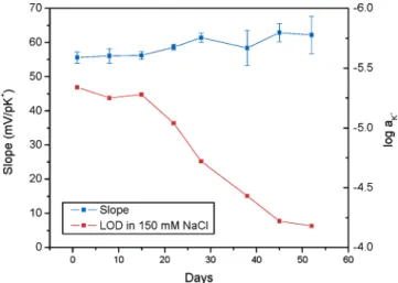
calibration curve was recorded every week according to the procedure described earlier. In between the tests, the array remained conditioned in 1 mM KCl solution. Figure 8 shows that the lifetime of the array is remarkably long. In fact, the response of the sensor remained stable for an entire month with the standard deviation staying below 4%, even reaching a minimum of 1.4% after 22 days. It must be emphasized that 15 out of 16 electrodes were functioning well during this entire period. After 1 month, the slope started to deteriorate and one more electrode failed. Besides, the lower detection limit slightly increased from the third week, but remained within the targeted working range during the 52 days of the experiment. This excellent lifetime result can partly be attributed to the large volume of plasticizer, carrier, and ionic sites that is situated below the micropipet and probably also to the geometrical configuration of the microelectrode that prevents penetration of water causing hydration of the surface forming a shunt. The optimal performance of the sensor as well
as its lifetime is greatly influenced by several factors, such as the conditioning of the sensors as well as their storage. In fact, after a first use, the ISE arrays could be kept dry for several weeks and be reused. As an example, the ISE array used for the lifetime experiment shown in Figure 8 was kept dry for 25 days and once rewetted presented a calibration curve of 53.0 ( 1.3 mV/pK+for 13 microelectrodes. The detection limit was of log aK) - 4.5, and the upper detection limit surprisingly rose from 100 to 200 mM K+. That particular array was used for more than 3 months.
Immersion in Physiological Solutions. It is intended to grow cells overnight in the microwell where the ISE array is located in normal cell culture medium that may include serum. For mea-surements, the medium will be replaced with a serum-free solution that presents an osmolarity similar to that of cytoplasm. This measurement strategy was applied by Stein et al.,34who used a modified light-addressable potentiometric sensor to monitor the acidification rate of cell populations. The characterization of the microelectrode response after being immersed overnight in physiological solutions is therefore important.
In measurements of biological samples, the loss of membrane ingredients into the sample is a primary concern. No effects of a likely leaching of membrane components on hepatocyte and cardiomyocyte cell culture viability were observed (results not shown). Another critical issue is the vulnerability of small surfaces to the adsorption of proteins. In this assay, after a first standard calibration, the ISE arrays were exposed to different physiological solutions under incubation conditions (37°C, 100% humidity, 5% CO2). After 24 h, the chip was removed from the incubator and a new calibration curve was recorded. The differences of the slope
(32) Fibbioli, M.; Morf, W. E.; Badertscher, M.; de Rooij, N. F.; Pretsch, E.
Electroanalysis2000, 12 (16).
(33) Cha, G. S.; Liu, D.; Meyerhoff, M. E.; Cantor, H. C.; Midgley, A. R.; Goldberg, H. D.; Brown, R. B. Anal. Chem. 1991, 63, 1666-1672.
(34) Stein, B.; George, M.; Gaub, H. E.; Behrends, J. C.; Parak, W. J. Biosens.
Bioelectron.2003, 18, 31-41.
Figure 8. Lifetime of ISE arrays. An array of 15 K+-selective microelectrodes was tested for more than 50 days. Calibration curves were performed in 150 mM NaCl. LOD, limit of detection.
Figure 7. Potential-time transients of 6-µm microelectrodes filled with membrane A under continuous-flow condition (12.6 µL/s). The
concentration of the KCl solutions was alternated between 1 and 10 mM for time intervals of∼2.5 min. The background electrolyte was 150 mM
sensitivity of the two calibration curves and their associated standard deviations were considered to be indicators of the contamination of the membrane due to the presence of proteins and growth factors. Table 2 summarizes the calibration results of K+-selective microelectrodes with 6-µm diameter after successive exposures to different physiological solutions. It must be men-tioned that the array tested had a history of 2.5 months of use and therefore had smaller initial sensitivity. In the first test, immersion in PBS did not seem to affect the microelectrode response very much. Similarly, in test 2, after immersion in DMEM containing 1% serum the array response was near-Nernstian, with a slight increase in sensitivity. In contrast, a significant drop of sensitivity was observed in both tests 1 and 2, after contact with DMEM containing either 5 or 10% serum. Moreover, the standard deviations of the calibration curve slopes increased considerably in these latter solutions, indicating that the protein adsorption on the selective membranes was
inhomo-is still exploitable to monitor cell responses. Nevertheless, the extent of protein adsorption on microelectrodes’ surface is difficult to quantify.35
CONCLUSION
This paper describes the performance of an array of K+- and NH4+-selective microelectrodes for cell culture testing. The arrays comprise 16 silicon nitride micropipet-based microelectrodes with a diameter of 6 or 2 µm, integrated in a 200-µm-large and 350-µm-deep microwell. Different ion-selective membrane composi-tions were evaluated with respect to the electrode sensitivity, selectivity, functional lifetime, and stability. The results show that the microelectrodes with 5% PVC and, respectively, valinomycin/ DOS and nonactin/NPOE exhibit an adequate linear response range and selectivity for extracellular monitoring of, respectively, K+and NH
4+ions in cell cultures. Providing a periodic recalibra-tion, the functional lifetime of several weeks is also more than adequate for the envisaged application.
As shown by the preliminary tests, the sensitivity decreases upon exposing the K+-selective arrays to physiological solutions containing different concentrations of serum. However, as the decrease of the sensitivity is gradual, the monitoring of cell-based responses, such as apoptosis, necrosis, or differentiation, should be possible over a period of 2-3 days.
ACKNOWLEDGMENT
The authors thank the SAMLAB technical team for their help as well as the COMLAB. They also thank Dr. P. van der Wal for his helpful comments about the manuscript. The wire bonding was partly made at the CNS/NSF/NNIN facilities at Harvard University. S.G. and O.T.G. thank the Swiss National Science Foundation for, respectively, the SNF project 205321-103961 and the SNF advanced researcher grant PA00A-105032. This work was also partially supported by the National Institutes of Health, grants R01DK43371 and P41EB002503, and the Shriners Hospitals for Children.
(35) Burnett, R. W.; Covington, A. K.; Fogh-Andersen, N.; Kulpmann, W. R.; Lewenstam, A.; Maas, A. H.; Muller-Plathe, O.; VanKessel, A. L.; Zijlstra, W. G. Clin. Chem. Lab. Med. 2000, 38, 363-370.
Table 2. Microelectrodes Responses after Exposure to Different Physiological Solutions during 24 h at 37°C, 100% Humidity, and 10% CO2a slope mV/pK+ SD mV/pK+ n Test 1
initial calibration curve 52.7 1.3 13
after 24 h in PBS 1× 49.1 2.2 13
after 24 h in DMEM 45.5 4.1 13
after 24 h in DMEM + 10% FBS + 1% PS 39.5 7.9 13
Test 2
initial calibration curve 53.9 1.5 3
after 24 h in DMEM + 1% FBS + 1% PS 57.0 1.5 3
after 24 h in DMEM + 5% FBS + 1% PS 53.7 7.0 3
after 24 h in DMEM + 10% FBS + 1% PS 54.1 6.5 3
aThe initial slope characteristics are sub-Nernstian, since the test
was performed with a 2.5-month-old chip.
geneous. In summary, after exposure to physiological solutions, the ISE arrays still show a linear but sub-Nernstian response that