HAL Id: tel-00449332
https://tel.archives-ouvertes.fr/tel-00449332
Submitted on 21 Jan 2010HAL is a multi-disciplinary open access archive for the deposit and dissemination of sci-entific research documents, whether they are pub-lished or not. The documents may come from teaching and research institutions in France or abroad, or from public or private research centers.
L’archive ouverte pluridisciplinaire HAL, est destinée au dépôt et à la diffusion de documents scientifiques de niveau recherche, publiés ou non, émanant des établissements d’enseignement et de recherche français ou étrangers, des laboratoires publics ou privés.
Virgile Adam
To cite this version:
Virgile Adam. Mechanistic studies of photoactivatable fluorescent proteins: a combined approach by crystallography and spectroscopy. Biological Physics [physics.bioph]. Université JosephFourier -Grenoble I, 2009. English. �tel-00449332�
DOCTOR FROM THE UNIVERSITY JOSEPH FOURIER Specialty: Structural Biology & Nanobiology
Doctoral school: Chemistry and Life Sciences Publicly presented and defended by
Virgile ADAM
The 20th May 2009
MECHANISTIC STUDIES OF PHOTOACTIVATABLE
FLUORESCENT PROTEINS:
A COMBINED APPROACH BY CRYSTALLOGRAPHY
AND SPECTROSCOPY
Examining board
Chairman ... Pr. Michel ROBERT-NICOUD Institut Albert Bonniot, Grenoble, FR
Reporters ... Dr. Catherine ROYER Centre de Biochimie Structurale, Montpellier, FR Dr. Daniel PICOT Institut de Biologie Physico-Chimique, Paris, FR Examiners ... Pr. Gerd Ulrich NIENHAUS Institut für Biophysik, Ulm, DE
Pr. Johan HOFKENS Afdeling Moleculaire en Nanomaterialen, Leuven, BE Thesis supervisors ... Dr. Dominique BOURGEOIS Institut de Biologie Structurale, Grenoble, FR
Dr. Seán McSWEENEY European Synchrotron Radiation Facility, Grenoble, FR Doctoral thesis prepared at the European Synchrotron Radiation Facility (ESRF)
The cover picture represents the fluorescent protein IrisFP described in this thesis and which undergoes multiple color changes, making of it a powerful tool for bioimaging and biotechnological applications. The X-ray structure of IrisFP is shown in the center (gray ribbons) and the green and red rays represent multi-color light-emission by the protein. Pictures of crystals of IrisFP in its different forms (switched on/off, green/red) are shown around the central image, linked by arrows representing
THESE
Pour obtenir le grade de
DOCTEUR DE L’UNIVERSITE JOSEPH FOURIER
Discipline : Biologie Structurale et Nanobiologie Ecole Doctorale : Chimie et Sciences du Vivant
Présentée et soutenue publiquement par
Virgile ADAM
Le 20 Mai 2009
ETUDES MECANISTIQUES DES PROTEINES
FLUORESCENTES PHOTOACTIVABLES :
UNE APPROCHE COMBINEE PAR CRISTALLOGRAPHIE
ET SPECTROSCOPIE
Composition du jury
Président ... Pr. Michel ROBERT-NICOUD Institut Albert Bonniot, Grenoble, FR
Rapporteurs ... Dr. Catherine ROYER Centre de Biochimie Structurale, Montpellier, FR Dr. Daniel PICOT Institut de Biologie Physico-Chimique, Paris, FR Examinateurs ... Pr. Gerd Ulrich NIENHAUS Institut für Biophysik, Ulm, DE
Pr. Johan HOFKENS Afdeling Moleculaire en Nanomaterialen, Leuven, BE Directeurs de thèse ... Dr. Dominique BOURGEOIS Institut de Biologie Structurale, Grenoble, FR
Dr. Seán McSWEENEY European Synchrotron Radiation Facility, Grenoble, FR
Thèse préparée à l’Installation Européenne de Rayonnement Synchrotron (ESRF) en collaboration avec le département de biophysique de l’Université de Ulm, Allemagne
A
A
d
d
d
d
r
r
e
e
s
s
s
s
e
e
s
s
o
o
f
f
t
t
h
h
e
e
e
e
x
x
a
a
m
m
i
i
n
n
i
i
n
n
g
g
b
b
o
o
a
a
r
r
d
d
m
m
e
e
m
m
b
b
e
e
r
r
s
s
Pr. Michel ROBERT-NICOUD
Institut Albert Bonniot
CRI INSERM/UJF U823
Rond-point de la Chantourne
F-38706 La Tronche Cedex
E-mail:
michel.robert-nicoud@ujf-grenoble.frTel: +33(0)4 76 51 40 91 Fax: +33(0)4 76 51 40 92
Pr. Gerd Ulrich NIENHAUS
Universit
ät Ulm
Institut f
ür Biophysik
Albert-Einstein-Allee 11
D-89081 Ulm
E-mail: uli@uiuc.edu
Tel: +49(0)731 23050 Fax: +49(0)731 23059Current address:
Institut f
ür Angewandte Physik
Universit
ät Karlsruhe
Wolfgang G
äde Str. 1
D-76131 Karlsruhe
Pr. Johan HOFKENS
Katholieke Universiteit Leuven
Afdeling Moleculaire en Nanomaterialen
Celestijnenlaan 200f - bus 02404
B-3001 Heverlee
E-mail:
johan.hofkens@chem.kuleuven.be
Tel: +32(
0)1 6327 804Fax: +32(
0)1 6327 990Dr. Catherine ROYER
Centre de Biochimie Structurale
29, route de Navacelles
F-34090 Montpellier Cedex
E-mail: catherine.royer@cbs.cnrs.fr
Tel: +33(0)4 67 41 79 02 Fax: +33(0)4 67 41 79 13Dr. Daniel PICOT
Institut de Biologie Physico-Chimique
13, rue Pierre et Marie Curie
F-75005 Paris
E-mail: daniel.picot@ibpc.fr
Tel: +33(0)1 58 41 51 03 Fax: +33(0)1 58 41 50 24
Dr. Dominique BOURGEOIS
Institut de Biologie Structurale J.P. Ebel
41, rue Jules Horowitz
F-38027 Grenoble Cedex 1
E-mail: dominique.bourgeois@ibs.fr
Tel: +33(0)4 38 78 96 44 Fax: +33(0)4 38 78 51 22
Dr. Se
án McSWEENEY
European Synchrotron Radiation Facility
6, rue Jules Horowitz BP 220
F-38043 Grenoble Cedex
E-mail: seanmcs@esrf.fr
Tel: +33(0)4 76 88 23 62 Fax: +33(0)4 76 88 21 60
"Chacun sait que dans les rêves on ne voit jamais le soleil, bien qu'on ait souvent la perception d'une clarté beaucoup plus vive.
Les objets et les corps sont lumineux par eux-mêmes"
Gérard de Nerval (Aurélia), 1855
“They are ill discoverers that think there is no land, when they can see nothing but sea”
T
T
a
a
b
b
l
l
e
e
o
o
f
f
C
C
o
o
n
n
t
t
e
e
n
n
t
t
s
s
Table of Contents ... i
List of Figures ... iv
List of Tables ... vii
List of abbreviations ... viii
Remerciements / Acknowledgements ... ix
I.
STATE
OF
THE
ART
1
CHAPTER 1 -HISTORY OF THE FLUORESCENCE DISCOVERY 3 PART 1-PHOSPHORESCENCE, FLUORESCENCE OR LUMINESCENCE? ... 51 - Matter shining by its own: a story of phosphorescence ... 5
2 - The physics behind luminescence phenomena ... 6
PART 2-THE EXPLANATION OF AN ANCESTRAL MYSTERY ... 11
1 - The Luciferase and luciferin system ... 12
2 - The Æquorin and cœlenterazine system ... 13
CHAPTER 2 -FLUORESCENT PROTEINS SHED A NEW LIGHT ON A BIOLUMINESCENT WORLD 17 PART 1-THE GREEN FLUORESCENT PROTEIN ... 19
1 - Of bioluminescence and biofluorescence ... 19
2 - Biological applications of the GFP ... 20
3 - The structure of GFP ... 21
4 - The chromophore: a conjugated system ... 26
5 - The photobleaching phenomenon ... 33
PART 2-THE DISCOVERY OF ANTHOZOAN FLUORESCENT PROTEINS ... 36
1 - Fluorescent-like proteins are common in oceans ... 36
2 - Photochromic reversibly switchable fluorescent proteins ... 39
3 - Green-to-red photoconvertible fluorescent proteins ... 47
CHAPTER 3 -APPLICATIONS OF PAFPS AND AIM OF THE THESIS 55 PART 1-TRACKING ELEMENTS WITHIN LIVING CELLS ... 57
PART 2-SUPER-RESOLUTION MICROSCOPY USING PAFPS ... 58
1 - The resolution is limited by diffraction in far-field visible microscopy ... 58
2 - Defeating the resolution limit, the quest for nanoscopy ... 61
PART 3-AIM OF THIS THESIS WORK ... 67
II.
RESULTS
AND
DISCUSSION
71
CHAPTER 1 -PHOTOCONVERSION FROM GREEN TO RED 73 PART 1-STUDY OF THE PHOTOCONVERSION OF EOSFP ... 751 - Crystallization of EosFP ... 75
2 - Structures of the green and red forms of EosFP ... 77
3 - Observation of the photoconversion phenomenon ... 78
4 - Is there an intermediate state forming? ... 82
5 - Toward a better comprehension of the photoconversion mechanism ... 87
PART 2-DENDRA2: AN EFFICIENT PCFP ... 92
1 - Crystallization of Dendra2 ... 92
2 - Structure of Dendra2 ... 93
PART 3-IMPROVING THE MONOMERIZATION OF PCFPS ... 104
1 - Dimeric (V123T) and monomeric (V123T/T158H) mutants of EosFP ... 109
2 - Dendra2 ... 114
3 - Discussion and conclusion ... 115
CHAPTER 2 -PHOTOSWITCHING: A REVERSIBLE BLEACHING EVENT 117 PART 1-SPECTROSCOPIC CHARACTERIZATION OF A REVERSIBLE SWITCHING ... 119
1 - Discovery of a strange phenomenon ... 119
2 - The first protein being both a PCFP and a RSFP ... 122
3 - Reversible switching of the red form ... 123
4 - An intramolecular FRET effect ... 125
5 - When EosFP-F173S becomes IrisFP ... 127
PART 2-STRUCTURAL CHARACTERIZATION OF THE REVERSIBLE SWITCHING ... 130
1 - Structure solution of IrisFP ... 130
2 - The green-to-dark reversible switching is due to cis/trans isomerization ... 132
3 - Photoisomerization in the red state is also possible ... 135
4 - Which kind of isomerization is involved? ... 137
5 - Discussion and conclusion ... 138
PART 3-FURTHER STUDIES ABOUT THE PHOTOSWITCHING ... 137
1 - The chicken and the egg dilemma: which is the first to occur between protonation and isomerization? .. 142
2 - Can non-switchable FPs be switched anyway? ... 151
PART 4-PAFPS AS OPTICAL DATA STORAGE DEVICES? ... 156
1 - The interest of biophotonics in data storage ... 156
2 - Protein crystals as write-only 3D mass storage devices ... 160
3 - Protein crystals as rewritable biophotochromic 3D mass storage devices ... 163
CHAPTER 3 -PHOTOBLEACHING: AN INTRIGUING PROBLEM 167 PART 1-ABOUT PHOTOBLEACHING ... 169
1 - What do we know about photobleaching? ... 169
2 - What are the factors influencing photobleaching? ... 170
PART 2-EFFECTS OF UV-LIGHT AND X-RAYS ON A FLUORESCENT PROTEIN ... 172
1 - Bleaching of a FP with UV light ... 172
2 - Fluorescence of FPs is lost under X-rays ... 174
PART 3-STRUCTURAL BASIS OF PHOTOBLEACHING ... 175
1 - UV-light induced photobleaching ... 175
2 - X-ray induced photobleaching ... 177
3 - Visible light induced photobleaching ... 185
PART 4-DISCUSSION AND CONCLUSION ... 186
1 - A radical state is probably forming when FPs are submitted to X-rays ... 187
2 - Photobleaching by visible light ... 188
3 - Bleaching and blinking phenomena at the single molecule level ... 190
4 - Perspectives ... 191
III.
MATERIAL
&
METHODS
193
CHAPTER 1 -CRYSTALLOGENESIS AND CRYSTALLOGRAPHY 195 PART 1-PRINCIPLE OF CRYSTALLOGENESIS AND CRYSTAL GROWTH ... 1971 - Definition of a crystal ... 197
2 - Protein crystal growth ... 198
1 - Crystallization of Dendra2 ... 202
2 - Crystallization of EosFP-V123T (d1EosFP) ... 207
3 - Crystallization of EosFP-V123T/T158H (mEosFP) ... 207
4 - Crystallization of EosFP-F173S (IrisFP) ... 207
PART 3-CRYSTALLOGRAPHY AND DATA COLLECTION ... 208
1 - Basics of X-ray diffraction ... 208
2 - Calculation of electron density maps and refinement ... 210
3 - Softwares used ... 215
CHAPTER 2 -THE CRYOBENCH LABORATORY 217 PART 1-OVERVIEW OF THE FACILITY ... 219
PART 2-THE DIFFERENT MODES AVAILABLE AT THE CRYOBENCH ... 221
1 - Absorbance and fluorescence microspectrophotometries ... 222
2 - Raman spectroscopy ... 227
3 - Fluorescence lifetime measurements ... 232
CHAPTER 3 -POWER DENSITIES AND QUANTUM YIELDS 233 PART 1-CALCULATING POWER DENSITIES ... 235
1 - Case of an experimental setup using a convergent light... 235
2 - Case of an experimental setup using a divergent light ... 236
PART 2-CALCULATING PHOTOSWITCHING QUANTUM YIELDS ... 239
1 - Stretched exponential function ... 239
2 - General formula of the quantum yield ... 240
3 - Example ... 241
CHAPTER 4 -RESTRAINTS ON THE CHROMOPHORES 243 1 - Link between the chromophore and the rest of the protein ... 245
2 - Restraints on the torsion angles ... 246
3 - Restraints on the planarity ... 247
IV.
CONCLUSIONS
&
PERSPECTIVES
249
V.
APPENDICES
257
L
L
i
i
s
s
t
t
o
o
f
f
F
F
i
i
g
g
u
u
r
r
e
e
s
s
Figure I.1.1 - Simplified Perrin-Jabłoński diagram and photographs of F. Perrin & A. Jabłoński ... 7
Figure I.1.2 - The mirror image rule and photographs of J. Franck & E. Condon ... 9
Figure I.1.3 - The different kind of luminescence phenomena illustrated by some photographs. ... 11
Figure I.1.4 - Mechanism of the firefly bioluminescence involving Luciferase & luciferin ... 13
Figure I.1.5 - Mechanism of Æquorea bioluminescence involving Æquorin and cœlenterazine ... 14
Figure I.1.6 - Æquorea victoria and a photograph of O. Shimomura ... 15
Figure I.2.1 - Mechanism of the energy transfer between the Æquorin and the GFP in Æquorea ... 19
Figure I.2.2 - Photographs of D. Prasher, M. Chalfie and R.Y. Tsien ... 20
Figure I.2.3 - Overall structure of GFP ... 22
Figure I.2.4 - The different types of -barrel foldings in Porin, GFP and RBP ... 23
Figure I.2.5 - Post-translational formation of green fluorescent proteins chromophores ... 25
Figure I.2.6 - Illustration of the constraints imposed to the GFP chromophore by its environment. ... 26
Figure I.2.7 - Hybridization and electron delocalization in phenol and phenolate ... 27
Figure I.2.8 - Resonance structures of the protonated and anionic chromophores ... 28
Figure I.2.9 - Diagram representing the HOMO and LUMO frontier orbitals ... 30
Figure I.2.10 - Representations of the HOMO for the neutral and anionic GFP chromophores ... 31
Figure I.2.11 - Representations of the HOMO and LUMO of the GFP neutral chromophore ... 31
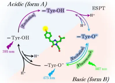
Figure I.2.12 - Scheme of the GFP Förster cycle involving an excited state proton transfer ... 32
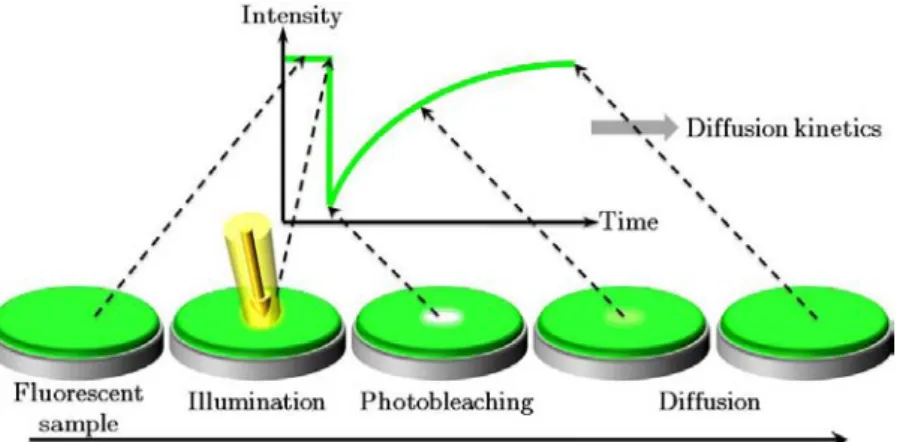
Figure I.2.13 - The FRAP technique uses the photobleaching phenomenon as an advantage ... 33
Figure I.2.14 - The FRET pair formed by CFP and YFP ... 35
Figure I.2.15 - Photograph of Y. Hirschberg ... 40
Figure I.2.16 - The color of Dronpa variants and absorption spectra of Dronpa, rsFastLime & Padron .. 42
Figure I.2.17 - Engineering of cFP484 into teal fluorescent proteins ... 43
Figure I.2.18 - Maturation of some chromophores of anthozoan FPs ... 46
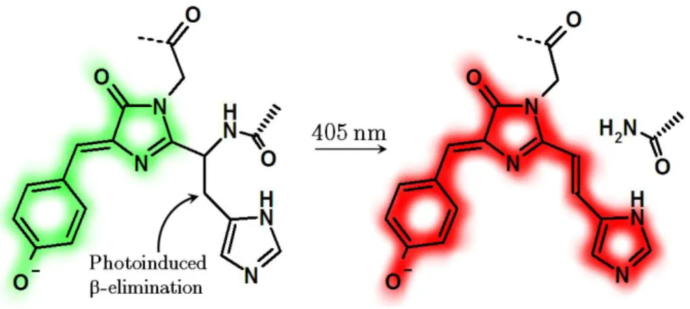
Figure I.2.19 - Photoinduced backbone cleavage of the chromophore in Kaede-like PAFPs ... 48
Figure I.2.20 - Photographs of A. Miyawaki, G.U. Nienhaus and S. Lukyanov ... 49
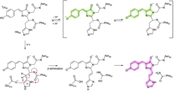
Figure I.2.21 - Proposed mechanism for the green-to-red photo-induced conversion of EosFP ... 50
Figure I.3.1 - An example of application of EosFP in dynamical microscopy ... 57
Figure I.3.2 - The parasitic phenomenon of diffraction causes the formation of an Airy disc ... 59
Figure I.3.3 - Photograph of E.K. Abbe and J.W.S. Rayleigh ... 59
Figure I.3.4 - The Rayleigh criterion ... 60
Figure I.3.5 - Resolution in far-field microscopy ... 61
Figure I.3.6 - The principle of STED microscopy ... 63
Figure I.3.7 - Photographs of W.W. Webb, S.W. Hell, E.Betzig and X. Zhuang ... 64
Figure I.3.8 - Principles of PALM and STORM sub-diffraction microscopy techniques ... 65
Figure I.3.9 - The idea behind the PALM/STORM super-resolution techniques ... 66
Figure I.3.10 - Superimposition demonstrating the common -barrel structure of different FPs ... 68
Figure II.1.1 - The different crystal shapes of EosFP ... 76
Figure II.1.2 - The chromophore environment in green and red forms of EosFP ... 78
Figure II.1.3 - The interest of PCFPs ... 79
Figure II.1.4 - The color of EosFP ... 80
Figure II.1.5 - Electrophoresis gels showing the photo-induced cleavage of PCFPs ... 81
Figure II.1.6 - Samples of EosFP used for TCSPC measurements and fluorescence decays ... 83
Figure II.1.7 - Fluorescence spectra of EosFP being photoconverted, passing through a yellow state ... 85
Figure II.1.8 - Spectroscopic isolation by temperature of a reversible yellow-emitting form ... 86
Figure II.1.9 - Calculated reaction pathway for the photoconversion mechanism of EosFP ... 88
Figure II.1.10 - The new photoconversion mechanism proposed for EosFP ... 89
Figure II.1.11 - The trans-to-cis isomerization of the chromophoric histidine of KikGR in its red form .. 91
Figure II.1.12 - Crystals of Dendra2 ... 92
Figure II.1.13 - The structure of Dendra2 ... 95
Figure II.1.14 - Close-up of the interactions between the Dendra2 chromophore and its environment .... 97
Figure II.1.15 - Superimposition of the chromophore environment in EosFP and Dendra2 ... 98
Figure II.1.16 - Spectroscopic signature of Dendra2 depending on its protonation state ... 100
Figure II.1.17 - Comparison of the chromophore environments of DsRed, mOrange and mKO ... 102
Figure II.1.18 -Absorbance and emission spectra of red Dendra2 at pH 10 ... 105
Figure II.1.19 - Comparison of the H-bonds in the vicinity of DsRed and Dendra2 chromophores ... 106
Figure II.1.20 - Concentration-dependent oligomerization of EosFP ... 107
Figure II.1.21 - Interfaces present in a typical tetrameric anthozoan FP ... 108
Figure II.1.24 - Zoom on the A/C interface of mEosFP ... 111
Figure II.1.25 - Superposition of EosFP and Dendra2 ... 115
Figure II.1.26 - Comparison between the interfaces formed in several crystal structures ... 116
Figure II.2.1 - Drop containing crystals of EosFP-F173S submitted to illumination at 488 nm ... 120
Figure II.2.2 - Reversible thermal absorbance recovery of a solution of EosFP-F173S ... 121
Figure II.2.3 - Series of absorbance spectra showing the light-induced switching of EosFP-F173S ... 122
Figure II.2.4 - Phototransformations on a part of EosFP-F173S crystals kept at room temperature ... 123
Figure II.2.5 - Wavelength dependency on the fluorescence recovery for red EosFP-F173S ... 124
Figure II.2.6 - Comparison between photoinduced transformations in wt-EosFP and EosFP-F173S ... 126
Figure II.2.7 - Red-to-green photoswitching due to the intramolecular FRET effect ... 127
Figure II.2.8 - Spectroscopic characterization of the phototransformations of EosFP-F173S ... 128
Figure II.2.9 - Overall structure of IrisFP ... 130
Figure II.2.10 - Changes in the chromophore environment induced by the F173S mutation in EosFP. . 131
Figure II.2.11 - Structural changes of the chromophore pocket upon phototransformation of IrisFP ... 133
Figure II.2.12 - Space gained around the chromophore of IrisFP ... 134
Figure II.2.13 - Omit electron density maps of the various states of IrisFP ... 136
Figure II.2.14 - Scheme of a photochemical system relaxing via a nonadiabatic transition ... 137
Figure II.2.15 - Hula-twist and rotation mechanisms ... 138
Figure II.2.16 - Photoinduced transformations in IrisFP ... 139
Figure II.2.17 - Superposition of the chromophores of IrisFP, EosFP, Dronpa, and mTFP0.7 ... 140
Figure II.2.18 - Spectroscopic evolutions of EosFP & IrisFP depending on their protonation state ... 143
Figure II.2.19 - Raman spectra of IrisFP crystals depending of their light- or pH-induced switching .... 145
Figure II.2.20 - Photo-induced protonation and degradation at 100 K of IrisFP ... 147
Figure II.2.21 - Photo-induced protonation at 100 K of a solution of IrisFP ... 148
Figure II.2.22 - Proposition for light induced and a pH induced mechanisms of RSFPs ... 150
Figure II.2.23 - Spectral series of a solution of EosFP being photoprotonated with a 502-nm laser ... 153
Figure II.2.24 - Single crystal of lysozyme embedded inside a plastic matrix ... 158
Figure II.2.25 - Photograph of M. Göppert-Mayer ... 159
Figure II.2.26 - Single photon excitation versus two-photon excitation ... 159
Figure II.2.27 - Confocal microscopy 3D reconstructions of crystals of IrisFP and d1EosFP ... 160
Figure II.2.28 - In-crystallo burning ... 162
Figure II.2.29 - In crystallo rewritable burning using 2P photoswitching ... 164
Figure II.2.30 - Difference between 1P and 2P excitation spectra ... 165
Figure II.2.31 - Controlled drying/humidifying of an IrisFP crystal ... 166
Figure II.3.1 - Photobleaching of a crystal of EosFP at 100 K by illumination at 266 nm ... 172
Figure II.3.2 - Aspect of an IrisFP crystal submitted or not to a strong X-ray or UV irradiation ... 173
Figure II.3.3 - Study of damages induced by X-rays and 440-nm light on IrisFP at 100 K ... 174
Figure II.3.4 - Crystal of EosFP being illuminated by a 355 nm laser source ... 176
Figure II.3.5 - Comparison between absorbance and fluorescence decays induced by X-rays ... 178
Figure II.3.6 - Absorbance decay of an IrisFP crystal under an X-ray beam ... 179
Figure II.3.7 - LD-MD (and HD-standard) electron difference density map of IrisFP ... 181
Figure II.3.8 - LD-MD NCS-averaged electron difference density map of IrisFP ... 183
Figure II.3.9 - In crystallo Raman spectra of IrisFP at 100K before and after bleaching. ... 184
Figure II.3.10 - Proposed mechanism for X-ray induced radical generation in IrisFP ... 189
Figure III.1.1 - Representation of a crystal ... 197
Figure III.1.2 - Simplified solubility diagram ... 198
Figure III.1.3 - Photograph and drawing of crystallization trays ... 199
Figure III.1.4 - Tools used to prepare a crystallization experiment by the streak seeding technique ... 200
Figure III.1.5 - Some of the first crystallization results obtained for Dendra2 ... 202
Figure III.1.6 - First screenings used to determine the main crystallizing agents for Dendra2 ... 203
Figure III.1.7 - Sparse-Matrix crystallization of Dendra2 ... 204
Figure III.1.8 - Low molecular weight SDS-PAGE showing two batches of Dendra2 ... 205
Figure III.1.9 - Re-purification of Dendra2 ... 206
Figure III.1.10 - An example of diffraction pattern obtained at the ESRF beamline ID14-4 ... 208
Figure III.1.11 - The Ewald sphere, the limiting sphere and the diffraction condition ... 210
Figure III.2.1 - The Cryobench laboratory ... 220
Figure III.2.2 - Different types of microloops for mounting crystals on the Cryobench or beamlines ... 221
Figure III.2.3 - Sketch of the Cryobench setup for in-crystallo absorption experiments ... 222
Figure III.2.4 - Sketch (and picture) of the Cryobench setup for in-crystallo fluorescence experiments . 223 Figure III.2.5 - Increasing gap between absorbance and fluorescence when concentration increases ... 224
Figure III.2.6 - Cryobench setup allowing the separation between actinic and probe laser excitations .. 225
Figure III.2.7 - Photograph of the online microspectrophotometer developed at the ESRF ... 226
Figure III.2.8 - Photograph of Sir C.V. Raman ... 227
Figure III.2.9 - Principle of Rayleigh and Raman scatterings ... 228
Figure III.2.10 - Diagram representing the Rayleigh and Raman scatterings ... 229
Figure III.2.11 - Raman intensity depends on the excitation wavelength ... 229
Figure III.3.1 - Optical properties of the objectives used at the Cryobench microspectrophotometer .... 235
Figure III.3.2 - Drawing of an experimental setup using a divergent light ... 237
Figure III.3.3 - Timetrace of a fluorescence decay during the red-to-dark photoswitching of IrisFP ... 241
Figure III.4.1 - Constraints used on the planarity of green and red chromophores ... 247
Figure III.4.2 - Torsion of the chromophore in the green-cis, green-trans and red-cis forms of IrisFP ... 248
Figure V.2.1 - Representation of recording surfaces details for several generations of laser discs ... 263
Figure V.2.2 - Illustrated phylogeny of cnidarians ... 264
Figure V.2.3 - Map showing the world repartition of main corals producing FPs and A. victoria ... 264
Figure V.2.4 - Complete taxonomy of cnidarian animals producing GFP-like proteins ... 265
L
L
i
i
s
s
t
t
o
o
f
f
T
T
a
a
b
b
l
l
e
e
s
s
Table I.2.1 - The different types & spectroscopic properties of photoactivatable fluorescent proteins ... 53
Table II.1.2 - Results of TCSPC measurements performed on EosFP crystals ... 84
Table II.1.3 - Crystallization data for green and red forms of EosFP and green form of Dendra2 ... 93
Table II.1.4 - Data collection statistics for green and red forms of EosFP and green form of Dendra2... 94
Table II.1.5 - Optical properties of Dendra2 ... 99
Table II.1.6 - Data collection statistics for monomeric and dimeric variants of EosFP ... 113
Table II.2.7 - Spectroscopic properties of EosFP-F173S as compared to its wild-type parent EosFP .... 129
Table II.2.8 - Data collection statistics of the different forms of IrisFP reported in this work ... 132
Table II.2.9 - Values of the halftimes for photoprotonation and deprotonations of EosFP ... 154
Table II.3.10 - Crystallographic statistics for non-illuminated and illuminated states of EosFP ... 177
Table II.3.11 - Data collection statistics for the LD and MD data sets of IrisFP ... 179
Table III.1.12 - Crystallization data for monomeric and dimeric variants of EosFP ... 207
L
L
i
i
s
s
t
t
o
o
f
f
a
a
b
b
b
b
r
r
e
e
v
v
i
i
a
a
t
t
i
i
o
o
n
n
s
s
AmSO4: ammonium sulphate
B-factor: temperature factor 𝐵 = 8𝜋² × 𝑢 ² (expressed in Å2) related to 𝑢 ², the mean square displacement of the
atomic vibration in the plane perpendicular to the plane h k l where atoms diffract in phase Bicine: N,N-Bis(2-hydroxyethyl)glycine
CALI: Chromophore Assisted Light Inactivation CCD: Coupled Charge Device
CCP4: Collaborative Computational Project, number 4 (www.ccp4.ac.uk) CNS: Crystallography and NMR System (http://cns-online.org)
CP: Chromo-Protein
EC: Enzyme Commission numbers
ESRF: European Synchrotron Radiation Facility (www.esrf.eu) Fcalc: calculated structure factors
Fobs: observed structure factors
FIONA: Fluorescence Imaging with One-Nanometer Accuracy FLIP: Fluorescence Loss In Photobleaching
FP: Fluorescent Protein
FRAP: Fluorescence Recovery After Photobleaching FRET: Förster Resonance Energy Transfer
FWHM: Full Width at Half Maximum GFP: Green Fluorescent Protein
HBDI: 4-hydroxybenzylidene-1,2-dimethylimidazoline (model compound of the GFP chromophore) p-HBI: p-hydroxybenzylidene-imidazolinone
HEPES: 4-(2-hydroxyethyl)-1-piperazineethanesulfonic acid I: Intensity
IBS: Institut de Biologie Structurale (www.ibs.fr) IR: Infrared
LD, MD, HD: Low Dose, Moderate Dose, High Dose
act
: Actinic wavelength
. max
em
: Maximal wavelength of emission
. max
ex
: Maximal wavelength of excitation MW: Molecular Weight
NCBI: National Center for Biotechnology Information (www.ncbi.nlm.nih.gov) NCS: Non-Crystallographic Symmetry
PAFP: Photo-Activatable Fluorescent Protein PALM: PhotoActivated Localization Microscopy PDB: Protein Data Bank (www.pdb.org) PEG: PolyEthylene Glycol
PSB: Partnership for Structural Biology (http://psb.esrf.eu) Rcryst:
hkl obs hkl calc obs F FF , Reliability factor indicating the crystallographic correctness of a model
Rfree:
T hkl obs T hkl calc obs F F F Rsym: hkl i i hkl i i hkl I hkl I hkl I ) ( ) ( )( , reliability factor comparing the intensity of symmetry-related reflections RCFP: Reef Coral Fluorescent Protein
rms: Root Mean Square, 𝑟𝑚𝑠 = 1
𝑛
n i ix
1 2 = 𝑥12+𝑥22+⋯+𝑥𝑛2 𝑛 for n values *𝑥1, 𝑥2, … , 𝑥𝑛+RSFP: Reversibly Switchable Fluorescent Protein STED: STimulated Emission Depletion
STORM: STochastic Optical Reconstruction Microscopy TCSPC: Time Correlated Single Photon Counting TIRF: Total Internal Reflection Fluorescence Tris: tris-(hydroxymethyl)aminomethane UV : Ultra-Violet
The Free R-factoris similar to the Rcryst but is calculated with a small fraction (i.e. 5%) of reflections randomly chosen to be part of test group T. This R factor, thus, is not biased by the refinement process.
R
R
e
e
m
m
e
e
r
r
c
c
i
i
e
e
m
m
e
e
n
n
t
t
s
s
/
/
A
A
c
c
k
k
n
n
o
o
w
w
l
l
e
e
d
d
g
g
e
e
m
m
e
e
n
n
t
t
s
s
H bien voil{, une page se tourne… la thèse est terminée et clôt ces années d’études et d’efforts pour réaliser un rêve d’enfance qui se concrétise aujourd’hui. J’aurais tellement de gens { remercier qui ont tellement compté pour moi durant des années que toutes les pages de cette thèse (pourtant nombreuses !) n’y suffiraient pas. J’espère que tous ceux dont j’oublierai le nom ne m’en tiendront pas trop rigueur. Je tenais tout de même à remercier un certain nombre nommément pour ces merveilleux moments, parfois difficiles mais de toute façon inoubliables.
Dominique Bourgeois, mon directeur de thèse, vers qui je suis arrivé seulement armé de ma sincérité, mon ignorance et ma bonne volonté et qui m’a offert sa confiance et un avenir. Depuis mon tout premier stage auprès de lui il y a maintenant presque huit ans, travailler { ses côtés a été un plaisir qui m’a mené { prendre plus confiance en moi, à devenir meilleur scientifique et à peut-être pouvoir me vanter d’avoir gagné son amitié. Je ne lui ai probablement pas assez dit { quel point je lui suis reconnaissant d’avoir joué un rôle si important pour moi et donc j’en profite ici pour lui dire un simple mais si profond « merci ». Ce n’est qu’un au revoir et certainement pas un adieu.
Je tiens { remercier les membres du jury m’ayant fait l’honneur d’examiner ce travail :
A mes rapporteurs, Dr. Catherine Royer et Dr. Daniel Picot, merci pour ces rapports si élogieux ! Dr. Catherine Royer, dont l’expertise en corrélation croisée de fluorescence, en spectroscopie sur molécule unique et en anisotropie de fluorescence permet de juger les résultats contenus dans ce rapport et d’apprécier la portée de ces résultats dans leurs futures applications. Merci d’avoir accepté de donner son avis certainement très juste sur ce travail.
Dr. Daniel Picot, que j’ai eu l’occasion de croiser à plusieurs reprises lors de congrès de biologie structurale et dont les capacités en cristallographie ne sont plus à prouver. De par son expérience en cristallographie des protéines photosensibles, son jugement sur ce rapport est précieux pour moi. Je ne saurai certainement pas me passer de cristallographie et donc nos chemins devraient se recroiser.
Pr. Michel Robert-Nicoud, que j’ai eu le plaisir et l’honneur d’avoir eu comme enseignant et qui m’a fait découvrir les merveilles de la fluorescence appliquée à la recherche avec les "F-techniques" que je ne suis pas prêt d’oublier. Merci à lui d’avoir accepté d’être le président de mon jury, et d’avoir jugé mon travail avec l’œil afuté d’un microscopiste. J’espère que mon travail servira { la communauté des microscopistes et acquérir dans les années { venir plus de connaissances me permettant d’apporter une nouvelle pierre à cet édifice.
Herr Dr. Prof. Uli Nienhaus und Frau Dr. Karin Nienhaus dafür, daß ich in Ihrer Arbeitsgruppe (Abteilung Biophysik) in Ulm immer so herzlich willkommen war, Ihre Hilfe im Kampf mit der deutschen Bürokratie, daß Sie es mir ermöglicht haben mit diesen wundervollen Proteinen zu Arbeiten und daß Sie immer alles gegeben haben um unserere Projekte erfolgreich voranzubringen.
Professor Hofkens, die niet alleen deze thesis nauwgezet beoordeeld heeft en daarbij hartelijk in de omgang was, maar mij, door me de komende jaren welkom te heten in zijn team in Leuven, ook het volste vertrouwen gaf. Ik hoop van ganser harte dat onze samenwerking bijzonder vruchtbaar zal zijn!
Dr. Sean McSweeney, director of the Macromolecular Crystallography (MX) group, for his continuous support during these years spent among the MX group. Thanks for having accepted me, for having integrated me so fast in the group and for all the last-minute details for the organisation of the defense!
I also wanted to thank Sine Larsen, scientific director at the ESRF, who was always available for me and trusted me and the project when we proposed it at the beginning of the thesis, as were very nice people with me all along these years, either at the MX group (Joanne McCarthy, David Flot, Dave Hall, Gordon Leonard and all the scientists and students) or elsewhere at the ESRF (Guillaume Potdevin and his gas detectors, Adeline Buffet and her alloys topographs, Sylvain Petitgirard and his high-pressure diamond-anvil cells…), IBS, EMBL and ILL… thanks for all this kindness and all those soft moments. I just can’t forget members of the PSB wetlabs: Samira Acajjaoui, Meike Stelter, Hayretin Yumerefendi, Tomaso Tosi, Sofia Caria, Ganesh Natrajan, Maxime Cuypers, Laurent Terradot, Cyril Dian, Amandine Lallemand and all the others who all participated to the nice ambience in which I evolved. All this wonderful period wouldn’t have been the same without those who shared the office with me: Charles Sabin, Wendy Rénier, Bernhard Pätzold, Therese Johansson and Isabel Baker... thanks for all these good moments!
Ma famille qui m’a bien sûr construit pour me permettre d’être celui que je suis, et au tout premier plan ma petite maman, merci pour tout ce que tu représentes à mes yeux, pour avoir été à toi seule pendant dix belles années (et toujours !) mes deux parents et assumé contre vents et marées. Je compte sur toi plus que jamais pour être { mes côtés durant toutes celles { venir. Merci d’avoir toujours cru en moi et avoir tout simplement fait qui je suis. Cette thèse t’est bien évidemment dédiée.
Bien sûr ma tendre épouse Marie, qui depuis des années n’a eu de cesse de me donner son amour et de croire en moi et en nous. Six ans après nos fiançailles et trois ans après notre mariage, je suis le plus heureux à tes côtés et tu as été ma force pour faire toujours mieux. Désormais nous allons continuer ce chemin avec notre petit Gabriel, merveilleux petit ange que tu viens de nous offrir il y a quelques semaines et qui représente la preuve par trois que l’avenir nous appartient.
Ma sœur et sa jolie famille : Didier, Marion, Laurie et Emmanuelle, famille soudée par-delà les saisons qui passent.
qu’est celui de la recherche scientifique. Je pense { tous ceux de l’équipe de cristallographie cinétique : Emanuela Fioravanti e la sua amicizia preziosa, che conosco dai miei primi giorni di tirocinio e che ho seguito sul cammino oscuro della tesi, Antoine Royant pour son amitié, tout ces bons moments au fil des années et ses précieux conseils et discussions scientifiques que j’ai toujours apprécié au plus haut point et n’oublierai pas, Philippe Carpentier pour toute la gentillesse dans la vie et lors des manips de photoblanchiment qui nous ont donné mal à la tête, mais aussi Jeremy Ohana, Guillaume Durin, Gergely Katona, Martin Weik, Jacques Colletier, Benoît Sanson… vous avez tous été une part très importante de mon chemin de tout petit stagiaire et de petit doctorant.
Un grand merci également { tous ceux qui m’ont aidé avec des techniques spécialisées { un moment ou à un autre de mon travail et sans qui j’aurais été vite bloqué : Alexeï Grichine de l’IAB (microscopie de fluorescence), Monika Budayova-Spano de l’UVHCI (neutrons), Mickael Wulff, Marco Cammarata et Friederike Ewald de l’ESRF (diffraction Laue), Yvain Nicolet et Xavier Vernède de l’IBS…
Mickaël Lelimousin, mon cher « très très bientôt docteur » de ces années de doctorat, qui en plus d’avoir été dans la même promo de DEA, a partagé avec moi les stress, joies, cafés, travaux et espoirs déçus ou récompensés de l’avancée de ce projet sur lequel il a également fait sa thèse soutenue à quelques jours de la mienne !
Anne Martel… la p’tite Anne, docteur ès-fil-de-soie, ce fut un réel plaisir de faire nos thèses côte à côte et de boire tous ces litres de thé. Je te souhaite de réussir et surtout d’être toujours au moins aussi motivée par ton travail, quelle que soit la voie dans laquelle tu t’engageras.
Charles Sabin, pote depuis si longtemps, nos chemins ne cessent de se croiser depuis le lycée, rien n’y fait on se ressemble finalement trop pour ne pas nous retrouver ensemble à nous poser des questions similaires sur tout et n’importe quoi. Merci d’avoir été présent aussi souvent (en particulier au déjeuner !) et d’avoir partagé avec moi les doutes et reprises de motivation, inhérents { la recherche.
Avoir passé toutes ces années dans ce cadre unique a été une superbe expérience pour moi. Quel plaisir enrichissant et rare de pouvoir partager chaque jour de la semaine des temps avec des gens de nationalités et de domaines scientifiques si différents, quel bonheur de pouvoir travailler aussi librement dans une variété de laboratoires aussi bien équipés que le synchrotron européen, le laboratoire de biologie moléculaire européen, l’institut Laue-Langevin, l’institut de biologie structurale, le commissariat à l’énergie atomique, l’institut Albert Bonniot… A l’orée de cette nouvelle vie qui s’ouvre { moi, je prie pour pouvoir dans l’avenir être amené { connaître de nouveau toute cette ouverture culturelle et scientifique.
R
R
é
é
s
s
u
u
m
m
é
é
g
g
é
é
n
n
é
é
r
r
a
a
l
l
e
e
n
n
f
f
r
r
a
a
n
n
ç
ç
a
a
i
i
s
s
A production de lumière par des êtres vivants comme les lucioles trouble les humains depuis la nuit
des temps. Des premiers écrits chinois aux études des savants du 19ème siècle, en passant par les
philosophes grecs, tous ont tenté de percer ce mystère qui sera successivement appelé phosphorescence puis bioluminescence. Il y a moins de 50 ans, la première production de lumière par un animal, non pas uniquement par réaction chimique mais également par fluorescence, était découverte avec l’identification de la protéine fluorescente verte (GFP) chez la méduse Æquorea victoria. L’isolation et le clonage de cette protéine il y a moins de 20 ans a permis à la fin des années 1990 un bond phénoménal en biologie cellulaire et recherche biomédicale, en permettant de marquer et suivre des protéines ou des organelles d’intérêts dans des cellules ou des organismes. Les efforts de génie génétique ont même permis les mutations de cette protéine, créant une véritable palette de couleurs disponibles pour la microscopie de fluorescence.
La recherche d’autres animaux marins générant des protéines fluorescentes (FP) a permis la découverte de molécules de couleurs et brillances variées, mais au début du 21ème siècle, la découverte des
protéines fluorescentes photoactivables (PAFPs), notamment chez les anthozoaires, a initié une révolution dans le domaine de la technologie des FP. Ces protéines fluorescentes sont en effet capables d’être irréversiblement photoconverties d'une forme fluorescente verte à une forme fluorescente rouge ou encore d’être réversiblement commutées entre des formes allumées ou éteintes, selon des longueurs d'onde d'excitation spécifiques. Les PAFPs sont actuellement intensivement employées dans les techniques de microscopie optique, particulièrement en “nanoscopie”, qui permet d'atteindre une résolution optique 10 fois meilleure que la limite théorique d’Abbe.
Tout au long de ce volume de thèse, nous présenterons d’abord l’état de l’art des protéines fluorescentes, depuis la découverte du phénomène de fluorescence jusqu’{ celle des protéines fluorescentes photoactivables. Les résultats des travaux présentés couvrent trois grandes problématiques actuellement débattues dans le domaine des PAFPs : les mécanismes de la photoconversion du vert au rouge, de la photocommutation réversible entre un état lumineux et un état non-fluorescent, et du photoblanchiment menant { l’extinction définitive des marqueurs biofluorescents.
Grâce à une approche combinée de diffraction des rayons X, de microspectrophotométrie en solution et sur cristaux, et de calculs de mécanique quantique et moléculaire, nous sommes parvenus à proposer un nouveau mécanisme réactionnel menant à la photoconversion du vert au rouge de EosFP, une PAFP photoconvertible du vert au rouge, issue d’un corail constructeur de récif, ainsi que la structure tridimensionnelle et la caractérisation de Dendra2, autre PAFP photoconvertible du vert au rouge, issue d’un corail mou et aux propriétés particulières. Les interfaces se formant dans les cristaux entre des
l’oligomérisation des protéines fluorescentes et de proposer des mutations que nous pensons importantes afin d’améliorer leur stabilité sous forme monomérique, étape essentielle pour l’obtention de biomarqueurs efficaces.
Nous avons également découvert la première protéine fluorescente photoactivable regroupant à la fois les propriétés de photoconversion du vert au rouge et de photocommutation réversible entre des états lumineux et non fluorescents, à la fois sous forme verte et sous forme rouge. Une telle protéine devrait se montrer utile en microscopie à super-résolution à deux couleurs où des protéines non phototransformées (vertes) et phototransformées (rouges) pourraient être localisées très précisément en même temps. Une application futuriste intéressante est celle de l’utilisation de ces protéines pour stocker des données soit de manière irréversible en utilisant les propriétés de photoconversion du vert au rouge, soit en permettant l’effacement et la réécriture en utilisant les propriétés de photocommutation réversibles. Même si de telles applications dans la vie courante sont pour l’instant irréalistes, une preuve de principe pour ces deux types de stockage est fournie dans cette thèse.
Enfin, nous nous sommes intéressés au photoblanchiment, étape irrémédiable et délétère menant à la perte du signal en imagerie de fluorescence. Nous avons étudié le photoblanchiment des PAFPs induit par les UV, la lumière visible et les rayons X et nous avons obtenu et caractérisé les déformations du chromophore associées { la formation d’un état radicalaire induit par les rayons X et probablement impliqué dans la voie de photoblanchiment des PAFPs.
Les perspectives essentielles de ce travail sont l’amélioration des PAFPs pour leur utilisation en biotechnologie et en nanoscopie mais de nombreuses études initiées durant cette thèse restent à faire : diffraction de neutrons, diffraction de rayons X Laue, mutagénèse...
I
I
.
.
S
S
T
T
A
A
T
T
E
E
O
O
F
F
T
T
H
H
E
E
A
The illustration represents an assemblage of several examples of green-to-red photoconvertible fluorescent proteins and experiments presented in this thesis. From left to right and from top to bottom: a green crystal of Dendra2, a red crystal of EosFP, green and red forms of EosFP, and a 3D evolution of absorption spectra of EosFP during green-to-red photoconversion.
Chapter 1
- History of the fluorescence discovery
Part 1 - Phosphorescence, fluorescence or luminescence? ... 5 1 - Matter shining by its own: a story of phosphorescence ... 5 2 - The physics behind luminescence phenomena ... 6 a - Absorption ... 7 b - Fluorescence ... 8 c - Phosphorescence ... 9 d - Non-radiative relaxations and delayed fluorescence ... 10 e - A wide variety of luminescence events ... 10 Part 2 - The explanation of an ancestral mystery ... 11 1 - The Luciferase and luciferin system ... 12 2 - The Æquorin and cœlenterazine system ... 13
R
R
é
é
s
s
u
u
m
m
é
é
e
e
n
n
f
f
r
r
a
a
n
n
ç
ç
a
a
i
i
s
s
Par une approche historique, ce chapitre introductif permet d’appréhender et de différencier les termes et notions complexes de phosphorescence, fluorescence et luminescence. Depuis la découverte des premières pierres émettant de la lumière dans le noir jusqu’aux animaux luminescents, les phénomènes physiques d’absorption, de fluorescence, de phosphorescence, de relaxation non radiative et de fluorescence retardée seront expliqués au travers d’exemples.
Nous nous intéresserons en particulier aux deux premiers systèmes enzymatiques menant à la bioluminescence qui ont été découverts : le système Luciférase/luciférine présent par exemple chez les lucioles et le système Æquorine/cœlentérazine, présent chez certains animaux marins.
Part 1
- Phosphorescence, fluorescence or luminescence?
1
- Matter shining by its own: a story of phosphorescence
EAR Bologna, in 1603, the alchemist Vincenzo Cascariolo studied stones that he exposed under sunlight and noticed that they were shining by themselves in the dark (Licetus 1640). Thinking that he just found something close to the philosopher's stone, he named this compound able to generate light in the dark after having been illuminated \phosphorus of Bologna", phosphorus meaning “light carrier” (from the Greek words [phos] meaning \light" and [pherein] meaning \to carry"). However, this compound was actually barium sulphide (baryte: BaSO4) and not the real phosphorus element, which was discovered
by the alchemist Hennig Brandt in 1669 from urine phosphates, and described eight years later by the chemist Johann von Löwenstern-Kunckel (von Löwenstern-Kunckel 1678). This phenomenon of light emission by an object without incandescence (sometimes called \cold light"), whatever the involved process, was thus qualified by the term of phosphorescence until late 19th century.
Between 1839 and 1841, Alexandre Edmond Becquerel studied the emission of visible light by calcium sulphur after samples were exposed to the ultraviolet (UV) part of the sunlight spectrum. He showed that this light was emitted at longer wavelengths than the one used to excite the object (Becquerel 1839). However, he qualified all the events of cold light production (by minerals or living organisms) by the term \phosphorescence".
Five years later, Sir Georges Gabriel Stokes studied the emission of visible light produced by quinine sulphate and crystals of fluorine (CaF2) under a UV irradiation. At the difference of
calcium sulphur, this light emission ceased when the exposure to UV light was stopped. He proposed for this phenomenon the term fluorescence (Stokes 1852) whose etymology is a neologism from the words fluorine and opalescence. In fact, more than forty years later, it was found that this fluorescence did not actually come from fluorine itself but from impurities inside, like yttrium or dysprosium (Lenard & Wolf 1889).
From then, it seemed that two different ways of producing light could coexist and the term luminescence (from the Latin lumen meaning \light") was proposed in 1888 by Eilhardt Wiedemann to refer to both phenomena of fluorescence and phosphorescence (Wiedemann 1888). Today, the phenomenon of luminescence is defined as being a \spontaneous emission of radiation from an electronically or vibrationally excited species not in thermal equilibrium with its environment"1. The phenomenon of fluorescence is defined as a \luminescence which occurs
essentially only during the irradiation of a substance by electromagnetic radiation"2 and the
phenomenon of phosphorescence is described as follow: \the luminescence involves a change in spin multiplicity, typically from triplet to singlet or vice versa. The luminescence from a quartet state to a doublet state is also phosphorescence"3.
2
- The physics behind luminescence phenomena
In spite of all those works and progresses, the phenomena of molecular absorption of photons (A), fluorescence (F) and phosphorescence (P) remained poorly understood until the 20th century.
In 1929, Francis Henri Jean Siegfried Perrin during his second PhD thesis, made a physical distinction between fluorescence and phosphorescence (Perrin 1926; 1929). The various transitions between the electronic ground state (S0), the singlet excited states (Sn>0) and the
triplet excited states (Tn>0) were all represented and summarized in a single chart by
Aleksander Jabłoński (Jablonksi 1935), known today as Perrin-Jabłoński diagram (Figure I.1.1).
1 Glossary of terms used in photochemistry, IUPAC recommendations 1996, 68, p.2252 2 Nomenclature for radioanalytical chemistry, IUPAC recommendations 1994, 66, p.2519
Figure I.1.1 - Simplified Perrin-Jabłoński diagram and photographs of Francis Perrin (up) & Aleksander Jabłoński (bottom)
This diagram must be seen as the graphical representation of the various possible transitions that a system in its ground state4 can exhibit once excited by an electromagnetic
wave. For sake of clarity, the version represented here is simplified and does not represent for example the rotational levels between the vibrational levels, but it allows getting a pretty accurate idea of the phenomena of absorption, radiative relaxations (like fluorescence and phosphorescence), or non radiative relaxations.
a
- Absorption
The molecular absorption of a photon that has the same energy than the energy difference between the lowest vibrational level of the ground state (S0) and one of the vibrational levels of
an excited state (Sn>0) of a molecule, allows an electron to cross this energy barrier and travel
from the ground state to one of the excited state levels. This absorption is faster (about 10-15 s)
4 \The state of lowest Gibbs energy of a system" - Glossary of terms used in physical organic chemistry, IUPAC recommendations 1994, 66, p.1118 (Gibbs energy was previously called free enthalpy or free energy)
compared to the timescale of the motion of atomic nuclei so that it is classically considered as being instantaneous (Franck-Condon principle).
The molecule relaxation, which will lead to the loss of the energy quantum that was absorbed, occurs in two steps. First, by relaxing to the lowest vibrational level of the excited state S1 by internal conversion (IC) in a time range comprised between 10-13 and 10-11 seconds,
thanks to the interactions of the molecule with its environment. Depending on the molecules and their environment, the lifetime of this excited state can vary from 10-12 to 10-9 seconds.
In a second step, there will be a relaxation of the molecule either by direct return to the ground state S0 with fluorescence emission or by phosphorescence emission with intersystem crossing to
an excited state called triplet state (T1) (Lewis & Kasha 1944). Alternatively, heat dissipation
may occur (non-radiative relaxation to the ground state) with a new internal conversion without photons emission.
b
- Fluorescence
In the case of fluorescence, the return to the ground state S0 is preceded by the relaxation
from the excited vibrational level that was reached to the lowest vibrational level of the S1
excited state. For most fluorophores, the vibrational energy level spacing for S0 and for S1 is
about the same size, which makes that excitation and emission spectra resemble a lot (this is not true anymore for higher excited states). The probability that an electron in S1 returns to a
given vibrational level of S0 is proportional to the overlap between these states, as represented
by the Franck-Condon energy diagram (Figure I.1.2). The return to S0 will thus be generally
achieved through an elevated vibrational level, which will then relax by internal conversion to the lowest vibrational level, relax to the equivalent elevated vibrational level of S0 and finally
transitions produce a typical mirror image of the fluorescence spectrum compared to the absorption spectrum; this is called the mirror image rule (Franck & Livingston 1941).
Figure I.1.2 - The mirror image rule. Left: Franck-Condon diagram showing the example of the 0-2 absorption/relaxation; Middle: photographs of James Franck (top) and Edward Condon (bottom); Right: the probability of the transitions creates the mirror image structure between the absorption and
fluorescence spectra
Since there is a loss of energy during this process, the fluorescence spectrum will be shifted toward less energetic wavelengths (bathochromic or red shift) than the ones that were used for the excitation: this is called the Stokes shift. In solution, this shift is even more pronounced because of a solvent relaxation phenomenon in the S1 state. The influence of the solvent is
indeed far from being negligible since the motion of solvent molecules is much faster (~ps) than the fluorescence lifetime (~ns). This has the consequence that solvent molecules can rearrange around the excited-state dipole in about 10-10 s (Lakowicz 2006). This solvent relaxation lowers
the excited molecule energy and thus here again a bathochromic shift is observed.
c
- Phosphorescence
In the case of phosphorescence, a crossing from the singlet excited state S1 to a triplet
excited state T1 is qualified as intersystem crossing (ISC). This isoenergetic non-radiative transition reverses the excited electron spin. The probability of an ISC is increased if the vibrational levels of the two states involved (singlet excited and triplet) overlap. Finally, after
an internal conversion to the lowest vibrational level of the triplet state, a last ISC conversion will allow the return to the (singlet) ground state. Because of the spin flippings, such ISC are very improbable and even qualified as \forbidden transitions" and for this reason, the lifetime () of the triplet state T1 is way longer than the one of S1 (10-6 to 104 seconds, several hours for
e.g. europium compounds) and the shortest phosphorescence lifetimes are close to the longest fluorescence lifetimes. However, lifetimes are not sufficient to distinguish between fluorescence and phosphorescence; since the lowest vibrational level of T1 is lower than the one of S1, the
internal conversions and intersystem crossings will result in a smaller loss of energy compared to the simple relaxation from a singlet excited state. A phosphorescence emission spectrum will thus be more shifted to high wavelengths (red shift) than a fluorescence emission spectrum.
d
- Non-radiative relaxations and delayed fluorescence
It is worthwhile noting that the phosphorescence lifetime is often so long that a number of collisions between the excited molecules and solvent or oxygen molecules favor the relaxation toward the ground state S0 without any photon emission (non-radiative relaxation) (Kautsky
1939). This quenching leads to the fact that most of the time, the phosphorescence is not observable in liquid phase (unless the molecule is in a hydrophobic solution or is protected from the solvent by its close environment) but only in rigid, crystal-like media. Finally, instead of directly relaxing from the triplet state toward the ground state, the inter-system crossing can be reversed from T1 to S1, leading to a delayed fluorescence.
e
- A wide variety of luminescence events
Since the definition of Wiedemann, quoting fluorescence and phosphorescence under the single term of luminescence, several other kinds of luminescence have been discovered (Figure I.1.3). The luminescence phenomena have thus been classified by their physical mechanisms. For example, the luminescence that needs the prior absorption of a photon (fluorescence and
phosphorescence) has been named \photoluminescence" while the one that needs a chemical reaction has been called \chemiluminescence".
Figure I.1.3 - The different kind of luminescence phenomena illustrated by some photographs. From left to right examples are shown of: chemiluminescence with the reaction of luminol with blood; electroluminescence with a nightlight; bioluminescence with a glow-worm; phosphorescence with a bottle
containing a strontium/europium compound shown under ambient light and total darkness, and fluorescence with a collection of fluorescent minerals.
Part 2
- The explanation of an ancestral mystery
When luminescence is produced by a living organism as a consequence of a chemical reaction, one talks of bioluminescence (hybrid word made of the Greek word [bios] meaning \life" and the Latin word lumen meaning \light"). The first observation that some plants or animals can glow in the dark is lost in History but the best known example of bioluminescence is of course the luminescence produced by \glow-worms" and especially fireflies (Lampyris noctiluca) during summer nights. This animal production of light is actually the most ancient written testimony of bioluminescence since some Chinese texts dated 1000-1500
BC describe this fact. No real explanations for this phenomenon were given during centuries. Naturally, some well-reads tried to understand this extraordinary phenomenon, but most of them ended with the somewhat useless conclusion that those organisms were glowing by nature. It is reported in the book \Aglow in the dark" (Pieribone & Gruber 2005) that Aristotle for example wrote "it is the nature of smooth things to shine in the dark" and Gaius Plinius Secundus (Pliny the Elder) wrote "it is the nature of these fishes to shine in darkness with a bright light when other light is removed". During the 17th century, Robert Boyle understood that the bioluminescent
light was cold and required air (Boyle 1672; 1680) but the biggest advancements in the study of bioluminescence only occurred during the 19th century.
Alessandro Volta had just invented his electric pile battery and the efforts to develop the electric light made scientists of this period, like Alexandre Edmond Becquerel, Edmund Newton Harvey or Victor Audoin, highly interested in understanding how light is created. They were especially paying a lot of attention to organisms capable of emitting what they were still calling phosphorescence or \phosphoric glow", like some annelids, fungi and glow-worms (Audoin 1840). Raphaël Horace Dubois was one of those scientists. He studied the West Indian firefly Pyrophorus and discovered the components and the origin of this enigmatic light emission: an enzyme and its substrate that he respectively called Luciferase and luciferin (Dubois 1887), from \Lucifer" meaning literary \light carrier" (from the Latin words lux (gen. lucis) meaning \light" and ferre meaning \carry").
1
- The Luciferase and luciferin system
The mechanism involved in this bioluminescence system is the oxidation of luciferin into oxyluciferin by the Luciferase, which is an ATP-hydrolyzing mono-oxygenase (EC 1.13.12.7). Along with ATP hydrolysis, the Luciferase will excite the luciferin molecule. Its relaxation is achieved through the formation of a radical form and finally to the luciferin decarboxylation into oxyluciferin, accompanied with the emission of a photon (Figure I.1.4).
Figure I.1.4 - Mechanism of the firefly bioluminescence involving Luciferase (PDB:1LCI,2D1R) & luciferin
Dubois, however, did not really explain this biochemical mechanism. It was made by Edmund Newton Harvey, one of the most important contradictors of Dubois, who preferred to call Luciferase \photogenin" and luciferin \photophelein" but spent almost all his career on the topic of animal bioluminescence, working especially on the luciferin and Luciferase from the crustacean Cypridina (EC 1.13.12.5). He allowed major improvements in the understanding of bioluminescence (Harvey 1917; 1919; 1920; 1924) until the end of his career in the 1950's (he died in 1959), at which date his team became world leading in bioluminescence research. His student Franck Johnson and himself, though, remained unable to crystallize Cypridina luciferin... this will be achieved by Osamu Shimomura, who joined their team.
2
- The
Æ
quorin and c
œ
lenterazine system
We know today that more than 700 animal genera use chemical molecules very similar to the couple luciferin/Luciferase to create light signals in the whole visible spectrum. Most of those species, though, are not terrestrial but live in oceans, like some fishes, bacteria or zooplankton. In the 1960's, Osamu Shimomura, working on the extraction of a new
bioluminescent protein from the jellyfish Æquorea victoria5
(Shimomura et al. 1962) discovered a new enzyme involved in bioluminescence that he naturally called Æquorin. This enzyme (EC 1.13.12.5) once activated by a calcium atom, works in a very similar way than the already known Luciferase, by exciting a prosthetic luciferin-like molecule called cœlenterazine, since it is found in cœlenterates organisms. Like in the case of the oxyluciferin (excited form of the luciferin), the activated form of the cœlenterazine, the cœlenteramide, will be decarboxylated along with the emission of a blue photon ( maxem. = 470 nm).
Figure I.1.5 - Mechanism of Æquorea bioluminescence involving Æquorin (PDB code: 1EJ3) and cœlenterazine
During this work, he also discovered another protein that he characterized later as being the very first protein capable of green light production (maximal emission at 507 nm) without any associated biochemical reaction. This protein was the first ever discovered that only needed a light excitation to produce its luminescence (maximal excitation at 475 nm). From what we said previously, we see that this kind of luminescence, even though being of a biological origin, should not be qualified of bioluminescence but of biofluorescence. This photoprotein was
5 After having sucessively been called Æquorea æquorea (Forsskål, 1775) and Æquorea forskalea (Péron 1809) & Lesueur, 1810), Murbach and Shearer (1902) identified individuals with morphological differences that they separated from the species forskalea to create the new species victoria. This distinction is today debated, but it seems that the gleaming properties of these jellyfishes (and
logically and simply called GFP, standing for green fluorescent protein (Hastings & Morin 1969) and will initiate the big revolution of biofluorescence.
Figure I.1.6 - Æquorea victoria (the light does not actually come from a luminescence but from external reflections) and a photograph of Osamu Shimomura (holding a tube filled with GFP)
Chapter 2
- Fluorescent proteins shed a new light on a
bioluminescent world
Part 1 - The Green Fluorescent Protein ... 19 1 - Of bioluminescence and biofluorescence ... 19 2 - Biological applications of the GFP ... 20 3 - The structure of GFP ... 21 a - Implications of a peculiar structure ... 21 b - Maturation and mechanism ... 23 4 - The chromophore: a conjugated system ... 26 a - Conjugated systems ... 26 b - Proton transfer and pH-dependent fluorescence... 29 5 - The photobleaching phenomenon ... 33 6 - The photoactivation phenomenon ... 34 Part 2 - The discovery of anthozoan fluorescent proteins ... 36 1 - Fluorescent-like proteins are common in oceans ... 36 a - DsRed, first member of a large family ... 36 b - Glowing by nature?... Fluoroproteins & chromoproteins ... 37 c - Under which form are chromophores the most stable? ... 38 2 - Photochromic reversibly switchable fluorescent proteins ... 39 a - Dronpa ... 40 b - mTFP0.7 ... 43 c - asFP595 ... 44 d - Other RSFPs ... 44 3 - Green-to-red photoconvertible fluorescent proteins... 47 a - Kaede ... 47 b - KikGR ... 48 c - EosFP ... 49 d - Dendra ... 51 e - Other PCFPs ... 52
R
R
é
é
s
s
u
u
m
m
é
é
e
e
n
n
f
f
r
r
a
a
n
n
ç
ç
a
a
i
i
s
s
Dans ce chapitre, nous parlons de la protéine fluorescente verte (GFP) et de la révolution qu’elle a apportée dans le monde de la recherche biomédicale. La structure particulière de cette protéine est décrite ainsi que son mécanisme de formation et de fluorescence. La notion de systèmes conjugués et la dépendance en pH de la fluorescence de cette protéine sont exposées. Très rapidement, l’utilisation de la GFP en imagerie biomédicale a donné lieu à des efforts de bioingénierie et cette utilisation a été confrontée à des phénomènes photochimiques comme le photoblanchiment ou la photoactivation, qui sont également expliqués ici.
Ce chapitre décrit également la découverte des premières protéines fluorescentes découvertes dans d’autres animaux marins comme les coraux ou les anémones de mer, ce qui a permis d’accroître considérablement la gamme des couleurs disponibles pour la microscopie de fluorescence. Parmi ces nouvelles protéines, nous nous intéresserons particulièrement à des protéines fluorescentes qualifiées de photoactivables. Plusieurs exemples de ces protéines fluorescentes, soit capables d’être réversiblement éteintes, soit d’être irréversiblement converties d’une couleur d’émission { une autre sont discutés.