"A model-driven approach for designing
multi-platform user interface dialogues"
Mbaki Luzayisu, Efrem
Abstract
Human-computer interaction becomes sophisticated, multimodal and multi device and needs to be well-designed with the aim of facilitating application correction (i.e. to correcting errors/bugs in the application) or extension (i.e. adding new functionalities or modifying existing tasks). This thesis is focused on building a methodology of designing and specifying User Interface (UI) behaviour. The Unified Modelling Language (UML) is used to describe in detail the conceptual model and to define all its objects. The methodology flux diagram is provided with the specification of the consistency and the completeness properties of the transformation model. To support the methodology, we implement a graphic Dialog Editor in which Models are organized in three levels (abstract, concrete and final) according to Cameleon Reference Framework (CFR) and, whose process respects the Model Driven Engineering (MDE) approach. Furthermore, the use of Dialog Editor is illustrated through a simple exam...
Document type : Thèse (Dissertation)
Référence bibliographique
Mbaki Luzayisu, Efrem. A model-driven approach for designing multi-platform user interface dialogues. Prom. : Vanderdonckt, JeanA Model-Driven Approach for
Designing Multi-platform
User Interface Dialogues
By Efrem MBAKI LUZAYISU
A thesis submitted in fulfilment of the requirements for the degree of Doctor of Computer Science
of the Ecole Polytechnique de Louvain, Université catholique de Louvain
Examination committee:
Prof. François BODART, Facultés Univ. Notre-Dame de la Paix, Reader Prof. Manuel KOLP, Université catholique de Louvain, Reader Prof. Christophe KOLSKI, Université de Valenciennes, France, Examiner
Prof. Jean VANDERDONCKT, Université catholique de Louvain, Advisor Prof. Christophe De VLEESCHOUWER, Université catholique de Louvain, President
Prof. Marco WINCKLER, Université Paul Sabatier, France, Examiner
Acknowledgements
I would like to express my thanks to:
− My advisor, Prof. Jean Vanderdonckt, for his constant support and enthusiasm regarding my work.
− Professors François Bodart, Christophe Kolski, Manuel Kolp, Christophe De Vleeschouwer and Marco Winckler for accepting to participate to the jury of this thesis and for their constructive comments brought to earlier versions of this manuscript.
− My colleagues from the Louvain Interaction Laboratory (Lilab) at Université
catholique de Louvain and from Orfival SA.
− My wife (Virginie Bozzo Lelo) and my children (Evy, Cecilia and Lys) − All my family and friends.
This thesis has been achieved thanks to the support of:
− Pole of Research on Information and Services Management and Engineering (PRISME) at LSM.
− The SIMILAR network of excellence supported by the 6th Framework Program of the
European Commission, under contract FP6-IST1-2003-507609 (www.similar.cc). − The UsiXML Project supported by the ITEA2 Call 3 Program of the European
Commission, under contract 2008026 (www.UsiXML.org).
− The SERENOA Project supported by the 7th Framework Program of the European
Table of Contents
TABLE OF CONTENTS ... 1 TABLE OF FIGURES ... 5 TABLE OF TABLES ... 7 TABLE OF ABBREVIATIONS ... 8 CHAPTER 1 INTRODUCTION ... 10 1.1 Motivations ... 101.1.1 Challenge of Modelling Dialogues ... 10
1.1.2 Complexity of dialogue ... 10
1.1.3 Designing dialogue ... 11
1.2 What is dialogue or Behaviour ... 12
1.2.1 Generic definition ... 12
1.2.2 Particularity ... 12
1.3 Illustrations ... 13
1.3.1 Disney Humanoid Robot ... 13
1.3.2 Ticket machine ... 14 1.3.3 Surgery robot ... 14 1.3.4 Wii gameplay ... 15 1.4 Dialogue aspects ... 16 1.4.1 Cognitive Aspects ... 16 1.4.2 Conceptual Aspects ... 17 1.4.3 Implementation Aspects ... 17 1.4.4 Handling Aspects ... 18 1.5 Thesis ... 18 1.5.1 Thesis statement ... 18 1.5.2 Some Definitions ... 22 1.6 Reading Map ... 24
CHAPTER 2 STATE OF THE ART ... 26
2.1 Abstract Machines ... 27
2.1.1 Backus-Naur Form (BNF) grammars ... 27
2.1.3 Statecharts ... 30 2.1.4 And-Or graphs ... 30 2.1.5 Event-Response Languages ... 31 2.1.6 Petri Nets ... 32 2.2 Model-Driven Engineering ... 33 2.2.1 Introduction ... 33 2.2.2 MDE objective ... 34
2.2.3 MDE Basic Principles ... 35
2.3 User Interface Description Languages (UIDLs) ... 36
2.3.1 Extensible Interface Markup Language (XIML) ... 37
2.3.2 Hypertext Markup Language (HTML) ... 38
2.3.3 Wireless Markup Language (WML) ... 38
2.3.4 Voice Extensible Markup Language (VoiceXML) ... 39
2.4 UsiXML ... 39 2.4.1 Data Structure ... 40 2.4.2 Task Model ... 43 2.4.3 AUI Model ... 43 2.4.4 CUI Model ... 46 2.4.5 Dialogue Model ... 48 2.5 Conclusion ... 49 2.5.1 Overview ... 49 2.5.2 Concerns ... 54
CHAPTER 3 MODEL-DRIVEN ENGINEERING OF BEHAVIOURS ... 55
3.1 Methodology ... 56
3.1.1 Preliminary ... 56
3.1.2 Cameleon Reference Framework ... 58
3.1.3 Model-Driven Engineering ... 59
3.1.4 Applying the methodology ... 63
3.2 Conceptual Model ... 65 3.2.1 Dialogue granularity ... 65 3.2.2 Interactive object ... 66 3.2.3 Behaviour Model ... 67 3.3 Implementation ... 76 3.3.1 Software architecture ... 77 3.3.2 Programming ... 78 3.3.3 Script Editor ... 81 3.3.4 Mapping Editor ... 83 3.4 Conclusion ... 88
CHAPTER 4 APPLICATIONS OF SOFTWARE SUPPORT ... 89 4.1 Basic samples ... 89 4.1.1 Statement ... 89 4.1.2 Dialogue granularity ... 90 4.2 Connection Sample ... 91 4.2.1 Project editing ... 91 4.2.2 Project transforming ... 92 4.2.3 Code generating ... 92 4.2.4 Conclusion ... 93 4.3 CTI Application ... 93 4.3.1 Software components ... 93
4.3.2 Transaction Order data structure ... 96
4.3.3 Using Dialog Editor ... 96
4.4 Conclusion ... 100
CHAPTER 5 QUALITY CHARACTERISTICS OF DIALOG EDITOR ... 101
5.1 The Interviews ... 102 5.1.1 The questionnaire ... 102 5.1.2 Demographic data ... 104 5.1.3 Analysis of replies ... 106 5.2 Satisfaction survey ... 109 5.2.1 Methodology ... 111
5.2.2 Results and discussions ... 111
5.3 Applying ISO/IEC 9126 Sofware Engineering ... 116
5.3.1 Functionality ... 116 5.3.2 Reliability ... 117 5.3.3 Usability ... 118 5.3.4 Efficiency ... 120 5.3.5 Maintainability ... 120 5.3.6 Portability ... 121 5.3.7 Conclusion ... 121 5.4 Conclusion ... 121 CHAPTER 6 CONCLUSION ... 122 6.1 Global view ... 122 6.2 Summary of results ... 124
6.2.1 Theoretical and conceptual contributions ... 124
6.2.3 Tools developed ... 125
6.3 Future work in prospect ... 128
REFERENCES ... 129
Table of Figures
Figure 1. Disney’s Humanoid Robot learns to Play ... 13
Figure 2. Tokyo train ticket machine. ... 14
Figure 3. Surgery robot. ... 15
Figure 4. Playing golf with Wii. ... 16
Figure 5. Methodological Approach... 20
Figure 6. Reading Map. ... 24
Figure 7. Sample of BNF Rule. ... 28
Figure 8. Connection Sample; using BNF Rule. ... 29
Figure 9. Connec tion Sample, State transition diagram. ... 29
Figure 10. Connection Sample; Statechart diagram. ... 30
Figure 11. Sample Connection, And-OR Graph. ... 31
Figure 12. Sample Connection, Event-Response Diagram. ... 31
Figure 13. Sample Connection, Petri net. ... 32
Figure 14: Model complexity as a function of their expressiveness. ... 33
Figure 15. MDE Equation. ... 33
Figure 16. Object technology & Model engineering. ... 35
Figure 17. Constituent models in UsiXML. ... 40
Figure 18. UsiXML Development Process ... 42
Figure 19. UsiXML Task Model. ... 43
Figure 20. Top part of UsiXML Abstract User Interface. ... 45
Figure 21. Lower right part of UsiXML Abstract User Interface ... 45
Figure 22. Top part of CUI Model in UsiXML. ... 47
Figure 23. Method frame in Methodological diagram. ... 55
Figure 24. Models frame in Methodological diagram. ... 56
Figure 25. Software frame in Methodological diagram. ... 56
Figure 26. Application of CFR in our research. ... 59
Figure 27. Applying MDE with Toolkits. ... 60
Figure 28. Three types of engineering in Contexte of Use. ... 61
Figure 29. Extended Context of Use ... 62
Figure 30. Methodology steps. ... 63
Figure 31. Project Editing Algorithm. ... 64
Figure 32. The hierarchy of interactive objects classes. ... 67
Figure 33. Internal and external representation of Toolkits. ... 68
Figure 34. Conceptual modelling of behaviours for model-driven engineering. ... 69
Figure 35. Internal and external representation of mappings. ... 71
Figure 36. Example of a mapping for reverse engineering. ... 72
Figure 37. Example of "one-to-many" mapping. ... 73
Figure 38. Example of mapping for lateral engineering... 73
Figure 39. Dialogue script of an interactive object. ... 74
Figure 40. Script of Connection Class In Dialog Editor. ... 75
Figure 41. Recovering a previously saved history. ... 76
Figure 42. Dialog Editor Architecture. ... 77
Figure 44. Project main window in Dialog Editor. ... 78
Figure 45. Video demonstrations of the Dialog Editor. ... 79
Figure 46. A Recordset for native objects. ... 80
Figure 47. XML file corresponding to a UI Project. ... 81
Figure 48. Script Editor. ... 82
Figure 49. Objects Mapping. ... 84
Figure 50. Transformation rule... 84
Figure 51. Mapping interface. ... 87
Figure 52. Dialogue granularity. ... 90
Figure 53. Final User Interfaces of Login & Password. ... 91
Figure 54. Global view of CTI Application. ... 93
Figure 55. CTI application components. ... 94
Figure 56. CTI Configuration UI... 94
Figure 57. CTI Transaction UI. ... 94
Figure 58. CTI network agencies. ... 95
Figure 59. CTI Order by UML data model. ... 96
Figure 60. Open questionnaire used for interviews ... 103
Figure 61. Respondents Gender ... 104
Figure 62. Respondents Ages ... 105
Figure 63. Respondents Studies ... 105
Figure 64. Respondents Occupation ... 106
Figure 65. CSUQ questionnaire used for the satisfaction survey ... 110
Figure 66. CSUQ Parameters for Dialog Editor ... 111
Figure 67. Queries' cumulative assessments ... 113
Figure 68. Queries' standard deviation ... 114
Figure 69. The six quality characteristics of a software. ... 116
Figure 70. Dialog Scripting Interface ... 119
Figure 71. Global architecture. ... 141
Figure 72. Dialogue Automata. ... 141
Figure 73. VB6 Password Interface... 142
Figure 74. Visual Basic 6 IDE. ... 143
Figure 75. Adding Form in VB6 IDE. ... 144
Figure 76. VB6 IDE, adding Component. ... 145
Figure 77. Dialog Editor, adding items. ... 146
Figure 78. Dialog Editor, resizing item. ... 147
Figure 79. Dialog Editor, Choosing Mapping. ... 148
Figure 80. VB6 code of cMachine class. ... 150
Figure 81. VB6 code of Controller script. ... 151
Figure 82. VB6 of cBehaviour class. ... 152
Figure 83. VB6 code of Initialization Module. ... 153
Figure 84. VB6 Project Explorer. ... 154
Figure 85. Opening Project. ... 155
Figure 86. Project objects tree. ... 156
Table of tables
Table 1. Dialogues Properties ... 49
Table 2: Dialogue Formalisms Vs. Dialogue properties ... 51
Table 3. Interactive objects of the login & password example. ... 91
Table 4. Mapping from Abstract to Concrete ... 92
Table 5. Mappings from Concrete to Final User Interface. ... 92
Table 6. Tasks time distribution... 97
Table 7. Spent time for CTI Application. ... 98
Table 8. Code lines number for CTI Application. ... 99
Table 9. Analysis and Design Survey Feedback ... 107
Table 10. Modeling Survey Feedbacks ... 107
Table 11. Code Generation Survey Feedback... 108
Table 12. Cumulative responses assessments by query ... 112
Table 13. Per question statistics ... 114
Table 14: Current State of Dialog Editor ... 126
Table 15: Comparison user interface ... 148
Table of Abbreviations
ABBREVIATION FULL NAME
AC Abstract Container
ADO ActiveX Data Object
AGG Attributed Graph Grammar
AIC Abstract Individual Components
AIO Abstract Interaction Objects
AUI Abstract User Interface
BNF Backus-Naur Form
CIM Computing-Independent Model
CIO Concrete Interaction Objects
CRF Cameleon Reference Framework
CSS Cascading Style Sheets
CTI Congo Transfer International
CTT ConcurTaskTree
CUI Concrete User Interface
CUI Concrete User Interface
CUSQ Computer Usability Satisfaction Questionnaires
DBMS Data Base Management Systems
DSL Domain-Specific Language
DSM Domain-Specific Model
ECA Event-Condition-Action
FUI Final User Interface
GUI Graphical User Interface
HCI Human-Computer Interaction
HTA HTML for Applications
HTML HyperText Markup Language
IDE Integrated Development Environment
InfoQual Information Quality
IntQual Interface Quality
IOG Interaction Object Graph
IOG Interactive Objects
IS Information System
KBE Knowledge-Based Engineering
M2C Model-to-Code
M2M Model-to-Model
MDE Model-Driven Engineering
MIPIM Multimodal Interface Presentation and Interaction Model
PC Personal Computer
PSM Platform-Specific Model
SysUse System Usefulness
TA Transformation Atom
TAG Task-Action Grammar
TM Transformation Mapping
TR Transformation Rule
UI User Interface
UIDL User Interface Description Language
UIML User Interface Markup Language
USIXML USer Interface eXtensible Markup Language
VB Visual Basic
VBA Visual Basic for Applications
VoiceXML Voice Extensible Markup Language
WAP Wireless Application Protocol
WML Wireless Markup Language
1. Introduction
Chapter 1 Introduction
1.1 Motivations
As a first step, we analyze the reasons for our interest in the design of dialogues; we examine the challenge of working on or modelling interactive dialogues, the complexity of dialogues for interactive applications and the sophistication of designing dialogues.
1.1.1 Challenge of Modelling Dialogues
Natural language is at the heart of human dialogue, probably the most frequently used communication channel ever. Information Systems (ISs) do not escape from this observation: probably the most important part of an IS today lies in its capabilities to communicate information quickly, precisely and in a reliable way. More particularly, the User Interface (UI) of this IS is also concerned as it is considered to be the primary way of communicating with end users, who do not necessarily speak the IS’s language but their own language with their own dialogue.
Many aspects may influence the dialogue between a UI and its end users in any context of use [Cal03]: aspects related to the end user (e.g. native language, cultural background), aspects related to the computing platform (e.g. application type, operating systems, Integrated
Development Environment (IDE) used, technical requirements) and aspects related to the
environment in which the end user is carrying out her/his task with the IS (e.g. the location, the organization, the human factors of the corporate environment). Because of this diversity, designing any dialogue between a system and its end users remains a permanent challenge.
1.1.2 Complexity of dialogue
As known, computer applications progress constantly in term of complexity [Gat08, Han03]. In parallel, users’ needs become vary increasingly in interactive application. Indisputably, human-computer interaction becomes sophisticated, multimodal and multi device. This reality can be justified by the fact that computers today reach unimaginable levels of performance in calculation and memory.
Computers used to work in milliseconds, then moved up to microseconds and now are approaching nanoseconds for logic operations and picoseconds for the switches and gates in chips. Currently, NASA scientists are working to solve the need for computer speed using light itself to accelerate calculations and increase data bandwidth. What they are accomplishing in the lab today will result in the development of fast, super-miniaturized, super-lightweight and lower-cost optical computing and optical communication devices and systems.
1. Introduction
Human-Computer Interaction (HCI) is one of the fields most affected by the aforementioned
evolution. Before continuing, let us recall that HCI is a discipline concerned with the design, evaluation and implementation of interactive computing systems for human use and with the study of major phenomena surrounding them. Certainly, we note that the power of the computer never ceases to inspire HCI’ researchers. For example, a team of researchers has lately developed a system that uses computer vision to replace standard computer mouse functions with hand gestures [Car98, Duc07]. The system is designed to enable noncontact HCI, so that surgeons will be able to make more effective use of computers during surgery.
1.1.3 Designing dialogue
Interactive applications implemented in context described above must be well-designed with the aim of facilitating application correction (i.e. to correcting errors/bugs in the application) or extension (i.e. adding new functionalities or modifying existing tasks). In short, developer (designer, analyst or programmer) needs to have powerful tools which can enable him to have a total control of its application. In others words:
The developer must have a good requirements specification which defines ‘the best vision’: the target to aim at for throughout project. Skipping the specification phase, or not covering the details sufficiently, can lead to the same kind of misunderstanding between parties that can occur with an oral contract. Thus, having a good initial specification helps advance the subsequent design and implementation phases to successful conclusion. A good specification gives a well-defined target to aim for but it does not guarantee that the target will not move.
Once the specification is written, the developer must design his/her projects by partitioning the system into individual parts; defining and documenting the interfaces between the individual parts; deciding on and documenting the architecture of his/her solution, and deciding on and documenting the toolbox, libraries or components to be used.
In the development process, user interface design is so essential because in the opinion of many developers, over half of the development time is spent on the user interface portion. Indeed, apart from the characteristics of the computers to be used, the choice is not always easy for good language/toolbox/libraries for a good user interface relative to an interactive application. Also, a good part of the code is related to user interface. In addition, with the advent of the Internet, a series of unique challenges are posed for user interface design and development. New applications with innovative user interfaces are emerging (e.g. an e-commerce application with multiple user interfaces for personal digital assistants, Web, mobile telephone, etc.). For these applications, the developer does not necessarily know users’ needs and stereotypes and/or cannot sit down with them and walk them through the system. Therefore, adaptation and customization are now parts of the software developer's job. It is already true that people find that about 80% of
1. Introduction
software maintenance costs result from the problems users have with what the system does (usability), rather than from technical bugs.
User-centred design and usability testing are cost-effective solutions to this problem. So, easy to use (usability) oriented software development enhances human productivity and performance, reduces training time and costs, increases employee autonomy and performance, guarantees job quality due to uniform work practices as well as facilitates knowledge capitalization.
Before continuing, let us look in more deep at the notion of dialogue which constitutes our main theme.
1.2 What is dialogue or Behaviour
Now, let's understand what we mean by the term dialogue and fix the particularity of dialogues that we aim.
1.2.1 Generic definition
According to the Larousse dictionary, to communicate is to make common, to share or to transmit. Vivier [Viv96] states that the dialogue is a particular case of communication. Indeed, during a dialogue two or several entities interact together, often with the objective of producing an agreement. Thus, a dialogue supposes at least:
A transmitter: the activated entity at a given moment of the dialogue. The entity who engages, who acts, at a certain moment of communication;
A receiver: the non-activated entity at a given moment of the dialogue. The participating entities regularly exchange the roles of receiver and transmitter;
A message: the unity of the emitted data or information;
A code: the language and/or the jargon used as channel to pass the message; An objective: the goal of the message.
1.2.2 Particularity
Our research is focused particularly on dialogues whose entities for communication are respectively a human being and a machine. Thus, to avoid confusion with the concept of conversation,
dialogue, that is more generic, we adopt the term behaviour in this thesis. Indeed, we are interested in behaviour, more precisely in the specification of actions and/or information exchange, of human and/or machine actors during the execution process of an interactive task (e.g. pushing on a remote control to change television channel, seeking information on the Internet with a web navigator, transcribing orally a text via a program of voice recognition, etc.).
It is easy to continue this list because of, firstly, the constant progress of communication and information technologies, and, secondly, the type of the application which required more and more data flow.
1. Introduction
Moreover, the modern world is characterized by a remarkably rich evolution with regard to interaction technologies: on the one hand, traditional interaction technologies by graphical interface (windows, buttons, mouse, keyboards, sensors with wire or embarked, etc.), and, on the other hand, remote interaction, or sensitive interaction, which uses technologies containing sensors (distance, presence, displacement, sound, colour, temperature, etc.) of system of recognition per camera and computer, linked to systems of real-time analyses. Let us consider four examples that support our observations:
1.3 Illustrations
To fix ideas, let us consider four examples to illustrate the dialogue in interactive systems. These illustrations have the advantage of showing the diversity and the complexity of human-machine dialogues.
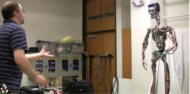
1.3.1 Disney Humanoid Robot
Disney aims to bring more physical interactions between visitors and its attractions machines. Disney Research Center have developed [Yam09, Yam10] a humanoid robot which has the capability of playing catch and juggling while still maintaining a safe distance between itself and participants - responding to entertainment robots in theme park environments which typically do not allow for physical interaction and contact with guests. An external camera system (ASUS Xtion PRO LIVE) is used to locate balls and a Kalman filter to predict ball destination and timing.
Figure 1. Disney’s Humanoid Robot learns to Play
The robot’s hand and joint-space are calibrated to the vision coordinate system using a least-squares technique, such that the hand can be positioned to the predicted location.
1. Introduction
1.3.2 Ticket machine
The touch screens for the purchase of transport documents, train tickets for example, are characterized by a simple and easily communication in appearance. But, in-depth this machine offers a powerful functionality. Indeed, in the case of cash payment, the machine is able to recognize money, to compute (addition, subtraction or multiplication), to print the difference between the price of the requested transport document and the money received. In the case of bank card payment, the machine is able to start a banking order to request in real-time the debit of the client account. Any transaction error between the customer and the machine can have unfortunate consequences. For example, traveller may not have his/her ticket and thus miss his/her transport, or, the company could lose money because the machine debits insufficient funds.
Figure 2. Tokyo train ticket machine.
1.3.3 Surgery robot
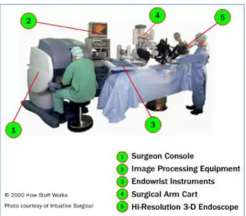
In surgery, computers assist surgeons in the realization of a diagnosis or the most precise and least invasive therapeutic gestures possible.
1. Introduction
Figure 3. Surgery robot.
In such an environment, the interface introduced between the surgeon and the patient revolutionizes many aspects. As we can see in the images Figure 3, one of the robots used in surgery is composed of a console of surgery with stereo viewer with three-dimensional display incorporated, a carriage of surgery with arms of instrumentation and a carriage of imagery. The surgeon operates using two manipulators. On the screen of posting, the ends of the instruments are aligned with the manipulators to ensure the natural and foreseeable movements of the instruments.
1.3.4 Wii gameplay
The Wii gameplay revolutionizes human-machine interaction in video games. Its interface makes it possible to play golf by making real gestures, the swing for example. It is also possible to fight with genuine punches in the air. In terms of interface, there is a clear rupture compared to the other plays with the console or the screen only. Wii allows the combination of several widgets simultaneously. Indeed, the real revolution in this system is its controller, called the Wii Remote. Shaped like a TV remote, it has been designed to be used easily by beginners and pros alike. Sensors determine the Wii Remote's position in 3-D space, which means that
racing-1. Introduction
game steering and a tennis swing, for example, are done through movements of the player’s hand/arm rather than by just his thumbs.
Figure 4. Playing golf with Wii.
1.4 Dialogue aspects
Among all models involved in Model-Driven Engineering (MDE) of User Interfaces (UIs) of any interactive application in general, or for a web application in particular, the dialogue model is probably one of the most challenging remaining problems for several reasons that we can be organized in four categories described below.
1.4.1 Cognitive Aspects
Lack of ontological definition: different terms, e.g. dialogue, navigation, behaviour, dynamics, conversation, the “feel”, are inconsistently used to refer to the dynamic aspects of a UI, as opposed to the presentation, which refers to as the static aspects of a UI, e.g. its layout. We hereby define a dialogue model as the model that captures all dynamic aspects of user interface behaviour. This therefore includes dynamics at any level of any object that may appear in a user interface. This definition will lead us to define five particular levels later on.
Lack of actors: a dialogue implies an exchange in real-time between two actors. That requires a good comprehension of each actor throughout the conversation. The great question is whether we can use this semantics of the dialogue when one of the actors
1. Introduction
is a machine. In this context, the dialogue can be seen as a functionality by which a human operator can interact, handle, supervise or lead an automated system. The problem becomes complicated when the exchange relates to two machines. Within the framework of our research, we will see a dialogue like a network of nodes. Each exchange between actors must correspond to a passage from a node to another (possibly the same one). Then, dialogue scenarii would be the various possible courses in this network.
1.4.2 Conceptual Aspects
Lack of precise abstraction: in principle, MDA suggests three levels of abstraction (i.e. computing independent model, platform-independent model and platform-specific model)[Rai04]. These three levels are rarely observed in the area of dialogue modelling where the platform-specific level remains predominant.
Lack of continuity: when two levels of abstractions are covered, it is not always obvious to see how model-to-model mappings (whether achieved through transformations or not) are assured to establish and maintain continuity between them.
Lack of expressiveness: the demand for more sophisticated dialogues calls for a dialogue model capable of accommodating the description of desired dynamic aspects, such as animations, transitions, the two traditional forms of adaptation (i.e. adaptability and adaptivity). A modern dialogue model should be expressive enough to model recent dynamic aspects.
Risk for modelling complexity: it is likely that a more expressive model would tend to be more complex to define and therefore to use in general. The question would be to find the best abstraction: a modelling which can make it possible to graduate complexity, allowing the analyst to better understand and thus better control the problem.
1.4.3 Implementation Aspects
Lack of techniques combining genericity and flexibility: developers lack techniques that would allow them to specify a user interface at an abstract, generic level, suitable for several platforms and contexts, while providing flexible, configurable adaptation to the specific target platforms.
Lack of performance: how to reach information quickly when the size of the database exceeds hundreds of gigabytes. Database performance tuning has become a very important activity. The goal is to minimize the response time of queries and to make the best use of server resources by minimizing network traffic, disk Input/output and CPU time.
1. Introduction
Lack of security: it is essential for the developer to make safeguard his application; significant data must be protected. For the Web applications in particular, the encryption techniques are more than necessary.
1.4.4 Handling Aspects
Lack of advanced user interface support: the ideal is that the representation to be made is as near as possible to reality. For example, playing tennis match with a Wii game, a ball cannot be represented by a bird. In the same way, for a weather chart an animation relating to a storm must be realistic. Thus, the user can very quickly interpret the danger without losing several minutes in the reading of the statistical data.
Lack of widget coverage: the choice of the graphic components is very important. According to the type of an application and the context of its use, it is invaluable that the interactive be as real as possible. If not, the user cognitive effort will be too great which could entail errors that can have fatal consequences in critical applications. Lack of user profile consideration: It is known that for a given interface, a beginner user
does not have the same behaviour as an expert. While working with a training application for example, user progression must be taken into account. Progressively as the user knowledge evolves, the system presents him with more advanced concepts.
1.5 Thesis
1.5.1 Thesis statement
Our objective is to build a methodology of designing and specifying User Interface (UI) behaviour. The aforementioned methodology must be at the same time structured, reproducible and independent of platform. It must also provide effective traceability for history management and its results will be reliable and demonstrable.
Firstly, we will remember that to specify a problem means to build methodically its statement as clearly as possible reducing to the maximum: ambiguities (words/terms with several meanings), contradictions (assertions being excluded one from the other), silences (absence or insufficiency of capital information), and the noises (amplification or exaggeration relative to not very useful information).
Methods of formal specification have the advantage of having a well-defined semantics. That makes it possible to work in a rigorous way and especially, valorisation (checking) supports end results compared to initial waiting [Pal94, Pat94]. It is partly true to believe that only the critical interfaces require a formal specification. As far as possible, it is always advised to specify any interface. Indeed, it rather often happens that developers spend much time when adding a simple button to an existing graphical window because the person at the origin of the interface is not present or if nobody knows which information is attached to which object. The situation becomes complicated when it is
1. Introduction
necessary for an application to evolve to another programming language and/or platform. In these cases, the existence of a specification is not superfluous.
Secondly, we hereby refer to presentation as being the static part of a UI such as the description of all windows, dialogue boxes, widgets and their associated properties. In contrast, we hereby refer to behaviour as being the dynamic part of a UI such as the physical and temporal arrangement of widgets in their respective containers. The behaviour has also been referred to as dialogue, navigation, or feels (as opposed to look for presentation). Here are some typical examples of behaviours: when a language is selected in a list box, the rest of a dialogue box is updated accordingly; when a particular value has been entered in an edit field, other edit fields are deactivated because they are no longer needed; when a validation button is pressed, the currently opened window is closed and another one is opened to pursue the dialogue.
Indeed, for many years, the hardest part in conceptual modelling of User Interfaces has been its dynamic part. All other aspects, such as presentation, help, tutorial, etc. have received considerable attention and results, especially in model-based approaches and model-driven engineering.
The behaviour received limited attention for many reasons: declarative languages that have been typically used for modelling presentation are hard to use for modelling behaviour. Procedural languages could be used instead, but then induce a mixed-model-based approach that is complex to implement. Languages used for the final behaviour are very diverse (mark-up or imperative), hold different levels of refinement (ranging from simple properties to sophisticated behaviours), are hard to abstract into one single level of abstraction (especially for different platforms), are hard to implement for model transformation.
There is no consensus about what type of model should be used: some models exhibit a reasonable level of expressiveness but prevent the designer from specifying advanced behaviours, while other languages benefit from more expressiveness but are more complex to handle, especially for non-trained designers. Which appropriate modelling approach to take is also open: taking the greatest common denominator across languages (with the risk of limited expressiveness) or more (with the risk of non-support), especially because many different implementations exist based on code templates and skeletons, deterministic algorithms, graph transformation, etc.
Finally, we are unaware of any existing approach that consistently applies model-driven engineering principles for UI behaviour from the highest level (computing-independent model) to the lowest level (platform-specific model). Existing approaches only address some parts of some levels.
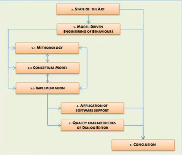
1. Introduction
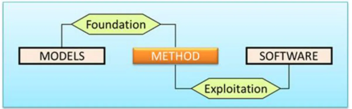
As the diagram below shows perfectly, the method we propose is based on a series of models. We will present each model in isolation before presenting the overall conceptual model of the methodology. Moreover, this model will be used to implement a software solution. The conceptual architecture and algorithms to exploit this software will be presented later.
Figure 5. Methodological Approach.
We emphasize that this was no way to present a software solution for production. Our goal was to demonstrate the usefulness of different concepts and how to combine them to design and specify the behaviour of an interactive application.
Admittedly, there exist several solutions or attempts at solutions concerning behaviour specification. But their answer to the problem is often only partial. Within the framework of our research, we wish to propose a transform approach whose four elements constitute its characteristics:
1. It is based primarily on the concept of interface objects. The user has the choice between creating his/her own objects, used existing interactive objects and making both. However, it’s important to determine which attributes, methods and events are necessary in dialogue script;
2. it gives a freedom concerning the level of specification. The user can choose to specify his interface at the abstract, concrete or final level;
3. it provides functionalities of passage intra and inter levels. The user could, for example, use the same abstract specification to provide two or several different concrete specifications. In the same way, it could start from a concrete specification to lead to another concrete specification by skews of the mappings;
4. it manages dialogue scripts traceability. It is possible to know who did what, which day and at what time. Also, if necessary, it is possible to cancel recent modifications, or simply to carry out an old version of a given script.
In order to address these objectives, we apply Model Driven Engineering (MDE) paradigm. The main characteristic is that each exploited model is a toolkit; a box of objects whose syntactic and semantic properties furnish dialogue scripts. Toolkits are classified
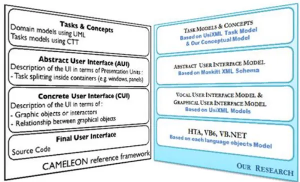
1. Introduction
according to the levels of abstraction of the Cameleon Reference Framework: task and domain, abstract user interface, concrete user interface and final user interface. The dialogue modelled at the abstract user interface level can be reified to the concrete user interface level by to-model transformation that can in turn lead to code by model-to-code generation. Definite concepts are generals but in order to validate results, we limited ourselves to support three programming languages: Visual Basic, HTML Applications (HTA) and Microsoft Visual Basic for Applications (VBA). Two computing platforms are addressed: Microsoft Windows and Mac OS X. In this way, the approach demonstrates the capabilities of the abstractions in order to cover multiple programming paradigms and computing platforms. Five levels of behaviour granularity are exemplified throughout the methodology that is supported by a dialogue editor, a model transformer and a code generator integrated into one single authoring environment called Dialog Editor or Behaviour Editor.
The translation into UsiXML (USer Interface eXtensible Markup Language) dialogue scripts built in to this authoring environment produces an effective solution for describing user interfaces and their behaviour with various levels of details and abstractions without limit of device, platform, modality and context.
Therefore, we will defend the following thesis:
Apply Model-Driving Engineering paradigm to build an approach for designing multi-platform user interfaces dialogue.
This methodology is model-based and is supported by a Dialog Editor, a model transformer and a code generator integrated into one single authoring environment. Also, regardless of the level specification, the developer has a single scripting language to manage the behaviour of an interface.
This way, scripts translation can constantly be done into UsiXML. As known, UsiXML describes user interfaces with various levels of detail and abstractions, depending on the context of use. UsiXML supports a family of user interfaces such as, but not limited to: device-independent, platform-independent, modality independent and ultimately context-independent. UsiXML allows the specifying of multiple models involved in user interface design such as: task, domain, presentation, dialogue and context of use, which is in turn broken down into user, platform and environment. Adding dialogue description from the above-mentioned authoring environment, UsiXML enriches a dialogue model.
1. Introduction
1.5.2 Some Definitions
1.2.2.a Human-Machine design methodology
HCI becomes increasingly varied and complex. In this context, design methods in this field aim at putting together, in a harmonious way, theories and techniques, to help with the assisted design of a better user interface. As we will see, in the state of art there exist today several approaches in the design of the HMI. Fortunately, in one field or another, each approach offers additional advantages to the Designer. It is advisable to say that the most interesting design methods are those which are at the same time simple to use and completely in agreement with the experiment and the user's needs.
1.2.2.b Concrete User Interface
A Concrete User Interface (CUI) is defined as the abstraction of any Final User Interface (FUI) with respect to computing platforms, but with the interaction modality given. According to MDE, it is a platform-specific model (PSM). A CUI is made up of Concrete Interaction Objects (CIO), which are abstractions of widgets found in those platforms. Any CIO may be associated with any number of Behaviours. Behaviour is the description of an Event-Condition-Action (ECA) mechanism that results in a system state change. The specification of behaviour may be broken down into three types of elements: an event, a condition and an action. An event is a description of a run-time occurrence that triggers an action. The general format of an ECA rule is: (ON Event, IF Condition, THEN Action). The event specifies when the rule should be fired, the condition specifies the logical condition when it should be fired and the action precises what methods should be executed for this purpose. In other terms, we can say that a Concrete User Interface (CUI) abstracts an FUI into a UI definition that is independent of any computing platform. Although a CUI makes explicit the final look and feel of an FUI. CUI can also be considered as a reification of an AUI at the upper level and an abstraction of the FUI with respect to the platform.
1.2.2.c Abstract User Interface
An Abstract User Interface (AUI) is defined as the abstraction of any CUI with respect to interaction modality. According to MDE, it is a platform independent model (PIM). An AUI is made up of Abstract Interaction Objects (AIOs), which are abstractions of CIOs found in existing interaction modalities and linked through abstract relationships. Therefore, an AUI only specifies interaction between a user and a system in totally independent terms. Only later on, once the interaction modalities are selected and once the target computing platform is elicited, this AUI will be turned into CIOs and final widgets, respectively. Abstract Interaction Object (AIO) may be of two types Abstract Individual Components (AIC) and Abstract Containers (AC). An Abstract Individual Component (AIC) is an abstraction that allows the description of interaction objects in a way that is independent of the modality in which it will be rendered in the physical world. An AIC may be composed of multiple facets. Each facet describes a particular function an AIC may endorse in the physical world order to conciliate computer-support and human control. In others terms, an Abstract User Interface (AUI) abstracts a CUI into a
1. Introduction
UI definition that is independent of any modality of interaction (e.g. graphical interaction, vocal interaction, speech synthesis and recognition, video-based interaction, virtual, augmented or mixed reality). An AUI can also be considered as a canonical expression of the rendering of the domain concepts and tasks in a way that is independent from any modality of interaction.
1.2.2.d UsiXML -User Interface eXtensible Markup Language
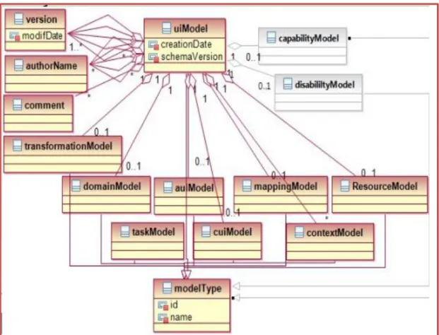
UsiXML (USer Interface eXtensible Markup Language), a User Interface Description Language aimed at describing user interfaces with various levels of details and abstractions, depending on the context of use. UsiXML supports a family of user interfaces such as, but not limited to: device-independent, platform-independent, modality independent and ultimately context-independent. UsiXML allows the specification of multiple models involved in user interface design such as: task, domain, presentation, dialogue and context of use, which is in turn broken down into user, platform and environment.
UsiXML is precisely structured into four levels of abstraction that do not all need to be specified to obtain a UI.
UsiXML can be used to specify a platform-independent, a context-independent and a modality-independent UI. For instance, a UI that is defined at the AUI level is assumed to be independent of any modality and platform. Therefore, it can be reified into different situations. Conversely, a UI that is defined at the CUI level can be abstracted into the AUI level so as to be transformed for another context of use.
UsiXML allows the simultaneous specification of multiple facets for each AIO, independently of any modality.
UsiXML encompasses a detailed model for specifying the dynamic aspects of UI based on productions (right-hand side, left-hand side and negative conditions) and graph transformations. These aspects are considered as the basic blocks of a dialogue model that is directly attached to the CIOs of interest.
Thanks to these dynamic aspects, virtually any type of adaptation can be explicitly specified. In particular, a transformation model consisting of a series of adaptation rules can be specified equally in an integrated way with the rest of the UI.
UsiXML contains a simplified abstraction for navigation based on windows transitions that is compatible with dynamics.
UsiXML is based on Allen relationships for specifying constraints in time and space at the AUI level that can in turn be mapped onto more precise relationships at the CUI level. These relationships are applicable to graphical UIs, vocal UIs, multimodal UIs and virtual reality UIs.
Similarly, a progressively more precise specification of the CIO layout can be introduced locally to concretize the Allen constraints imposed at the AUI level.
1. Introduction
UsiXML defines a wide range of CIOs in different modalities of use so as not to be limited only to graphical CIOs.
UsiXML already introduced a catalogue of predefined, canonical inter-model mapping that can be expanded and taxonomy of task types that facilitate the identification and selection of concepts at both the AUI and CUI levels.
1.2.2.e Task Model
A task model describes the various tasks to be carried out by a user in interaction with an interactive system. After a comparison of several task modelling techniques, an extended version of ConcurTaskTree (CTT) has been chosen to represent the user’s tasks and their logical and temporal ordering in the context of UsiXML. A task model is therefore composed of tasks and task relationships.
1.6 Reading Map
The remainder of this thesis is structured as follows:
1. Introduction
Chapter 2, State of the art, recalls and presents a global view of methods, models, technical and tools which are used in dialogue specification. Particular emphasis is placed on abstract machines, user interface description language and UsiXML. The main Chapter 3,
Model-Driven Engineering of behaviour, exploits the basic concepts of Chapter 2 to build our
methodology. It will present the overall conceptual model and the generic algorithm to be applied to achieve the behaviour of a given interactive task. This chapter discusses method, models and software branches of methodology approach. Chapter 4, Application
of software support, is the most practical of all. It presents two examples in which Dialog Editor was used; a simple and a more complex cases. Chapter 5, Quality characteristics of Dialog Editor, is based on ISO/IEC 9126 to examine technical, functional and interactive
characteristics of the software that we implemented. Chapter 6, Conclusion, will summarize our contributions and explore some avenues for future work.
2. State of the Art
Chapter 2 State of the Art
The model concept is often used to abstract a technique, a method, an algorithm or simply a heuristics. In general, dimensions of models are reduced in order to facilitate their comprehension and their application.
Dialogue models enable reasoning about UI behaviour. Consequently, dialogue models are often considered as a continuation of task model concepts. This explains why the task model has been extensively used to derive a dialogue model, for instance, in an algorithmic way [Luy03] or in a logical way supported by model-to-model transformations [Sch07] and graph grammars [Goe96, Lim04]. We hereafter give a brief survey of dialogue modelling methods that percolated into the field of Human-Computer Interaction (HCI) development methods [Gre86, Lim04, Mba02, Van98, and Van03]. A very wide spectrum of conceptual modelling and computer science techniques has been used over the years to model a dialogue [Ari88, Bas99, Boo07, Bre09, Cac07, Car94, Cow95, Dit04, Elw96, Gre87, Har87, Jac86, W3C08, Mba00a, Mba00b, Mba99], some of them with some persistence over time, such as, but not limited to: Backus-Naur Form (BNF) grammars [Elw96, Jac86], state-transition diagrams in very different forms (e.g.
dialogue charts [Ari88], dialogue flows [Boo07], abstract data views [Cow95], dialogue
nets [Cle06], windows transitions [Van03]), state charts [Har87] and its refinement for web applications [Cac07], and-or graphs coming from Artificial Intelligence (e.g. function chaining graphs [Mba08]), event response languages and Petri nets [Bas99]. Some algorithms [Luy03] have also been dedicated to support the dialogue design through models, such as the Enabled Task Set [Pat09].
Rigorously comparing these models represents a contribution that is yet to appear. Green [Cle06] compared three dialogue models to conclude that some models share the same expressivity, but not the same complexity. Cachero et al. examine how to model the navigation of a web application [Cac07]. In [Cle06], the context model drives a dialogue model at different steps of the UI development life cycle.
So far, few attempts have been made to structure the conceptual modelling of dialogues in the same way as has been done for presentation, the notable exception being applying StateWebCharts [Win03] with Cascading style sheets [Win08] in order to factor out common parts of dialogues and to keep specific parts locally.
The DIAMODL runtime [Tra08] models the dataflow dialogue as Face Data Binding and includes extensions for binding EMF data to SWT widgets in order to link domain and dialogue models. Statechart logic is implemented by means of the Apache SCXML engine [W3W08], while GUI execution utilizes an XML format and renderer for SWT.
2. State of the Art
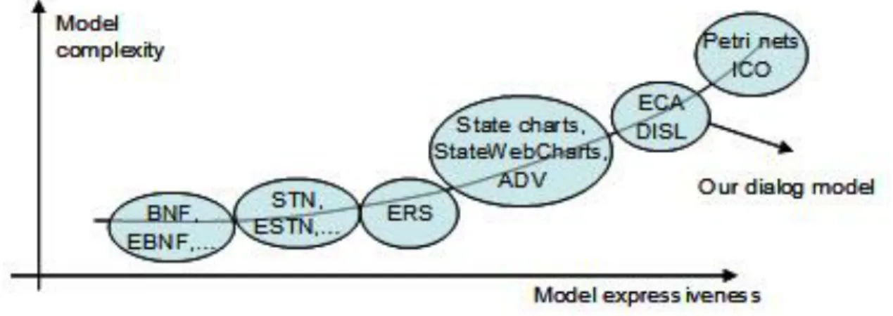
The Multimodal Interface Presentation and Interaction Model (MIPIM) [Sch05] could even model complex dialogues of a multimodal user interface together with an advanced control model, which can either be used for direct modelling by an interface designer or in conjunction with higher level models. Van den Bergh & Coninx [Van07] established a semantic mapping between a task model with temporal relationships expressed according to ConcurTaskTrees notation and UML state machines as a compact way to model the dialogue, resulting in a UML profile. Figure 14 graphically depicts some dialogue models in families of models.
Each family exhibits a certain degree of model expressiveness (i.e. the capability of the model to express advanced enough dialogues), but at the price of a certain model complexity (i.e. the easiness with which the dialogue could be modelled in terms specified by the meta-model).
We organize the rest of this chapter into three sections. The first deals with the modelling of dialogues by the use of abstract machines. The second explains dialogue management using UIDL (User Interface Description Languages) and the third gives some details on the characteristics of UsiXML.
2.1 Abstract Machines
Abstract machines, also known as mathematical models are used in the specification of dialogues since the pioneering work of Green [Gre86]. If we find it difficult to give an exhaustive list of these models, we intend to recall some definitions and basic concepts. This exercise will be useful because some of these models will be used in the methodology that we propose.
To illustrate the different abstract tools that we outline in this chapter, we use the example of a connection system that requires a login and a password. As in many systems, we assume that the user can make up to three attempts. This becomes interesting in the sense that each tool gives us the opportunity to emphasize one or more aspects of this problem of connection.
2.1.1 Backus-Naur Form (BNF) grammars
Backus-Naur Form, or BNF for short, is a notation used to describe context free
grammars. The notation breaks down the grammar into a series of rules which are used to describe how the programming languages tokens form different logical units In computer science, BNF is a metasyntax used to express context-free grammars: that is, a formal way to describe formal languages. John Backus and Peter Naur developed a context free grammar to define the syntax of a programming language by using two sets of rules: i.e. lexical rules and syntactic rules.
BNF is widely used as a notation for the grammars of computer programming languages, instruction sets and communication protocols, as well as a notation for representing parts
2. State of the Art
of natural language grammars. Many textbooks for programming language theory and/or semantics document the programming language in BNF. There are many extensions and variants of BNF, including Extended and Augmented Backus–Naur Forms (EBNF and ABNF).
They are typically used to specify command languages [Gre86, Jac86]. Command languages express commands that modify the state of the UI at the user’s initiative. Grammars are particularly good in detecting inconsistencies within command sets. An inconsistent UI may contain unordered or unpredictable interaction. Inconsistency renders the UI error prone and hard to learn. Reisner proposed an action grammar to describe Graphical UIs [Rei81]. Payne extended this grammar with their Task-Action Grammar (TAG) by covering three levels of inconsistency [Pay86]: lexical, syntactic and semantic. These established TAGs accuracy in predicting. Grammars are both efficient and effective for expressing sequential commands or users actions in general, but become complex for multimodality.
The actual reserved words and recognized symbol categories in the grammar represent "terminals". Usually, terminals are left without special formatting or are delimited by single or double quotes. Examples include: if, while, '=' and identifier.
In Backus-Naur Form, rules are represented with a "nonterminal" - which are structure names. Typically, nonterminals are delimited by angle-brackets, but this is not always the case. Examples include <statement> and <exp>. Both terminals and nonterminals are referred to generically as "symbols". Each nonterminal is defined using a series of one or more rules (also called productions). They have the following format:
A rule consists of one or more productions;
The production starts with a single nonterminal, which is the name of the rule being defined;
This nonterminal is followed by a ::= symbol which means “as defined as”. The ::= symbol is often used interchangeably with the symbol. They both have the same meaning.
The symbol is followed by a series of terminals and non-terminals.
2. State of the Art
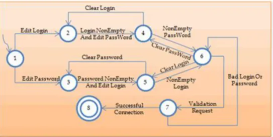
To return to the connection example, we can define a login as a string of lowercase alphabetic characters whose length does not exceed height. And, the password, a string that contains at least one lowercase letter, one uppercase letter, one number and one special character. Using regular expressions, we obtain:
Figure 8. Connection Sample; using BNF Rule.
2.1.2 State transition diagram
State transition diagrams are finite state machine representation that consists of a graph of nodes linked by edges [Gre86]. Each node represents a particular state of the system. Each edge species the input (i.e. event) required to go from one state to another. State transition diagrams have been subject to several extensions [Was85] and specializations, like Statecharts [Har87] that provide a means for specifying the dynamic behaviour of the interface. State transition diagrams present several drawbacks for modelling the UI. Indeed, today's UI tend to be modeless where one state can lead to many states. Furthermore this can be done using many different widgets of the UI. These two requirements match the quality criteria of reachability and device multiplicity.
Figure 9. Connec tion Sample, State transition diagram.
In consequence, state transition diagrams are prone to a combinatorial explosion and tend to replace nodes by screen prints. In [Van03], the transition space is restricted to events and transitions that are triggered by window managers in graphical state transition diagrams, thus supporting only simple windows transitions [Mba02]. Many other forms of dedicated state transition diagrams have been extensively for dialogue modelling without knowing which one is superior to another: dialogue charts [Ari88], dialogue flows [Boo04,Boo05a,Boo05b], hierarchical dialogue flows [Boo08], interaction object
2. State of the Art
graph [Car94], Abstract Data Views [Cow95], dialogue nets [Jan93], models [Sch07,Sch05].
2.1.3 Statecharts
As for state transition diagrams, statecharts are supported by a graphical representation of dynamic aspects of systems [Har87]. There exists research which specifically addresses the modelling of UI behaviour with statecharts [Oli01,Pau99]. Statecharts represent state variables with rounded rectangles called states. State-changing mechanisms are represented with edges between states. State-changing is triggered by events and can be further conditioned. Statecharts facilitate the representation of state nesting, state history, concurrency and external interruptions. Statecharts [Har87] propose solutions to the shortcomings of state transition diagrams: statecharts have representational capacities for modularity and abstraction. The number of states with respect to the complexity of the modelled system increases more slowly with statecharts than with state transition diagrams. Statecharts avoid the problem of duplicating states and transitions. States in statecharts are hierarchical and capable of representing different levels of abstraction. Statecharts are more convenient for multimodal interfaces as they provide nesting facilities, external interrupt specification and concurrency representation. Statecharts have also been specialized for specifying the dialogue of web interfaces through StateWebCharts [Win03], that can be edited via a SWCEditor [Win05].
Figure 10. Connection Sample; Statechart diagram.
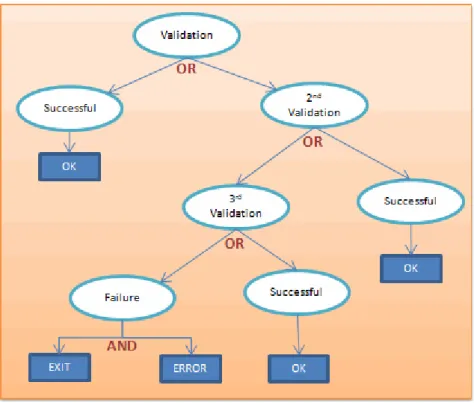
2.1.4 And-Or graphs
Borrowed from Artificial Intelligence, AND-OR graphs have been used to branch to various sub-dialogues depending on conditions, for instance in the EDGE system [Kle88]. And-or graphs have been expanded towards function chaining graphs [Bod95] by combining them with data flow diagrams [Van98].
2. State of the Art
Figure 11. Sample Connection, And-OR Graph.
2.1.5 Event-Response Languages
Event-Response Languages treat input stream as a set of events [Hil86]. Events are addressed to event handlers. Each handler responds to a specific type of event when activated.
Figure 12. Sample Connection, Event-Response Diagram.
This type is specified in a condition clause. The body of the event generates another event, changes the internal state of the system or calls an application procedure. Several
2. State of the Art
formalisms are suited for event-response specification. They can be distinguished following their capacity to manage dialogue state variables and concurrency control. Production rules and pushdown automata [Ols84] are often used to describe event-response specifications.
2.1.6 Petri Nets
Petri nets are a graphical formalism associated with a formal notation. Petri nets are best suited to represent concurrency aspects in software systems. Petri nets represent systems with state variables called places (depicted as circles) and state-changing operators called transitions (depicted as rectangles). Connections between places and transitions are called arcs (represented by edges). States contain items called tokens (represented by black solid dots distributed among places). State change is the consequence of a mechanism called firing. A transition is red when all of its input places contain tokens. Firing involves the redistribution of tokens in the net, i.e. input tokens are withdrawn from input places and output tokens are added in output places. Like State Charts, Petri nets hold mechanisms to represent additional conditions and nested states. Petri nets have the advantage of being entirely formal. Thus, model checking of interest properties of the dialogue model could be applied [Pal94].
Figure 13. Sample Connection, Petri net.
Figure 14 graphically depicts most of these dialogue models in families of models. Each family exhibits a certain degree of model expressiveness (i.e. the capability of the model to express advanced enough dialogues), but at the price of a certain model complexity (i.e. the easiness with which the dialogue could be modelled in terms specified by the meta-model). At the left of Figure 14 relay BNF and EBNF grammars since they are probably the simplest dialogue models ever but they do not support many dialogue aspects. We can find respectively State Transitions Networks and their derivatives, then
2. State of the Art
Event-Response Systems. Petri nets are probably the most expressive models that can be used to model dialogues, but they are also the most complex to achieve. Therefore, we believe that we should not be as expressive and complex as Petri nets, but a little bit below. This is why we have selected Event-Condition-Action systems, one example being the DISL language [Sch05].
Figure 14: Model complexity as a function of their expressiveness.
2.2 Model-Driven Engineering
2.2.1 IntroductionThe Model Driven Engineering, MDE for short, is a software engineering paradigm where models play a key role in all engineering activities (forward engineering, reverse engineering, software evolution…). In other words, MDE is a software design approach based on the concept of models and their transformation from one abstraction level to another or from one workspace to another [Bez04a, Bez04b]. The basic principle of MDE is "everything is a model", compared to the basic principle of object orientation "everything is an object".
2. State of the Art
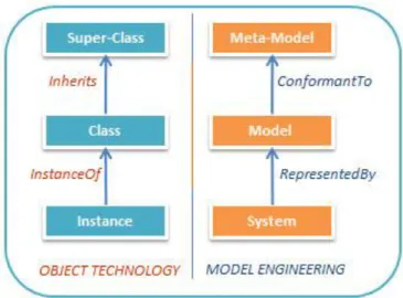
According to this definition, experts have revisited and transformed Niklaus Wirth's famous equation [Wir92] as shown in the Figure 15.
Before continuing this review, the main question is to fix what a “model” is. Indeed, in short, a model is an abstract representation of a system for some certain purpose and a meta-model is an abstract description of a model. The abstraction helps to neglect the less important aspects of a system, while concentrating on favourable parts that are desired to a specific study.
A model can come in many shapes, sizes, and styles. It is important to emphasize that a model is not the real world but merely a human construct to help us better understand real world systems. In general all models have an information input, an information processor, and an output of expected results.
A “model” can be seen as a measure, rule, pattern, example to be followed. In his book “Allgemeine Modelltheorie” (General Model Theory) [Sta73] Herbert Stachowiak describes the fundamental properties that make a Model:
Mapping: Models are always models of something, i.e. mappings from, representations of natural or artificial originals that can be models themselves. Reduction: Models in general capture not all attributes of the original represented
by them, but rather only those seeming relevant to their model creators and/ or model users.
Pragmatism: Models are not uniquely assigned to their originals per se. They fulfil their replacement function a) for particular – cognitive and/ or acting, model using subjects, b) within particular time intervals and c) restricted to particular mental or actual operations.
Finally, among the numerous publications that we found on Model-Driven Engineering (MDE), we adopt the description given in [Bro11]. Indeed, the MDE approach to application design is an approach that makes use of several conceptual models so that each model manages one or more well-defined part(s) of the application. Because of the conceptual nature of such models, they would not have to address the technological problems associated with the final application handled by the users [Sch06, Bro09].
2.2.2 MDE objective
MDE is an open and integrative approach that embraces many other Technological Spaces in a uniform way. A technological space is a working context with a set of associated concepts, body of knowledge, tools, required skills, and possibilities. Examples of technological spaces are Programming languages concrete and abstract syntax, Ontology engineering, XML-based languages, Data Base Management Systems (DBMS), Model-Driven Architecture (MDA), etc.
The goal of MDE is to increase both the short-term productivity, e.g. the amount of functionality delivered by a software artefact, and the long-term productivity, e.g. reducing the software artefacts' sensitivity for changes in personnel, requirements,