HAL Id: hal-01435117
https://hal.archives-ouvertes.fr/hal-01435117
Submitted on 6 Mar 2020
HAL is a multi-disciplinary open access
archive for the deposit and dissemination of
sci-entific research documents, whether they are
pub-lished or not. The documents may come from
teaching and research institutions in France or
abroad, or from public or private research centers.
L’archive ouverte pluridisciplinaire HAL, est
destinée au dépôt et à la diffusion de documents
scientifiques de niveau recherche, publiés ou non,
émanant des établissements d’enseignement et de
recherche français ou étrangers, des laboratoires
publics ou privés.
Impact Study on the Methodology used for
Photon-Heating Calculations in Material-Testing
Reactors
Matthieu Lemaire, Claire Vaglio-Gaudard, A. Lyoussi, Christelle
Reynard-Carette
To cite this version:
Matthieu Lemaire, Claire Vaglio-Gaudard, A. Lyoussi, Christelle Reynard-Carette. Impact Study on
the Methodology used for Photon-Heating Calculations in Material-Testing Reactors. IEEE
Transac-tions on Nuclear Science, Institute of Electrical and Electronics Engineers, 2015, 63 (3, 2),
pp.1499-1506. �10.1109/TNS.2016.2560261�. �hal-01435117�
Impact Study on the Methodology used for
Photon-Heating Calculations in Material-Testing Reactors
Matthieu Lemaire, Claire Vaglio-Gaudard, Abdallah Lyoussi and Christelle Reynard-Carette
Abstract–Determination of photon heating by calculation is an
important issue for the Jules Horowitz Reactor (JHR), the next international Material-Testing Reactor (MTR) under construction in the south of France. Accurate knowledge of photon heating in structure materials and irradiation devices is necessary for JHR design and safety studies. In this paper, we quantify the impact of different photon-heating calculation routes by comparing absorbed dose and KERMA calculations (Kinetic Energy Released per MAss) from two different Monte Carlo codes, TRIPOLI-4.9® and MCNP (Monte Carlo N-Particle transport code). These calculations are carried out in JHR-representative geometries with the nuclear-data library JEFF3.1.1 and the photon-data library EPDL97. Discrepancies amounting to up to 18% between absorbed dose and KERMA are found in JHR irradiation devices and are linked to charged-particle transport effects taking place in heterogeneous materials of small dimensions. In a JHR-assembly cell, discrepancies of about 1% on photon KERMA and of about 3% on absorbed dose are highlighted between the two Monte Carlo codes. These latter discrepancies are small compared to typical sources of uncertainty for Monte Carlo calculation (for instance, nuclear data uncertainty) and are supposed to be due to differences in the processing of gamma-production data by neutron interactions and to differences in electromagnetic-shower models and implementation between the two codes.
I. INTRODUCTION
HE Jules Horowitz Reactor (JHR) [1] is the next international Material-Testing Reactor (MTR) under construction in the south of France at CEA Cadarache (French Alternative Energies and Atomic Energy Commission). It will typically host about 20 simultaneous irradiation experiments of fuel samples and material samples. These experiments will help us better understand the complex phenomena occurring during the accelerated ageing of materials and the irradiation of nuclear fuels.
Photon heating, i.e. photon-energy deposition, is mainly responsible for temperature rise in non-fuelled zones of nuclear reactors, including MTR internal structures and irradiation devices. As temperature is a key parameter for physical models describing the behavior of material, accurate control of temperature, and hence photon heating, is required in irradiation devices in order to perform an advanced suitable analysis of future experimental results [2]. From a broader point of view, JHR global attractivity as a MTR depends on its
Manuscript received April 3, 2015.
M. Lemaire, C. Vaglio-Gaudard, A. Lyoussi, are with the French Alternative Energies and Atomic Energy Commission CEA, DEN, DER, Cadarache, F-13108 Saint Paul Les Durance, France (e-mail: matthieu.lemaire@cea.fr).
C. Reynard-Carette is with the Aix Marseille Université, CNRS, Université de Toulon, IM2NP UMR 7334, 13397, Marseille, France.
ability to monitor experimental parameters with high accuracy, including photon heating.
Strict control of temperature levels is also necessary in terms of safety. As MTR structures are warmed up by incident photons, they must be appropriately cooled down to prevent creep deformation or melting. Cooling-power sizing is based on calculated levels of photon heating in MTR. Due to these safety concerns, accurate calculation of photon heating with well-controlled bias and associated uncertainty as low as possible is all the more important.
There are two main kinds of calculation bias: bias coming from nuclear data on the one hand and bias coming from physical approximations assumed by computer codes and by general calculation route on the other hand. The former must be determined by comparison between calculation and experimental data; the latter by calculation comparisons between methodologies and between codes. In this presentation, we focus on this latter kind of bias.
Nuclear heating is represented by the physical quantity called absorbed dose (energy deposition induced by particle-matter interactions, divided by mass). Its calculation with Monte Carlo codes is possible but computationally expensive as it requires transport simulation of charged particles, along with neutrons and photons. For that reason, the calculation of another physical quantity, called KERMA (Kinetic Energy Released per MAss), is often preferred, as KERMA calculation with Monte Carlo codes only requires transport of neutral particles. However, KERMA is only an estimator of the absorbed dose and many conditions must be fulfilled for KERMA to be equal to absorbed dose, including the condition of electronic equilibrium [3].
Also, Monte Carlo computations of absorbed dose still present some physical approximations, even though there are only a limited number of them. Some of these approximations are linked to the way how Monte Carlo codes apprehend the transport simulation of charged particles and the productive and destructive interactions between photons, electrons and positrons. There exists a huge variety of electromagnetic shower models which tackle this topic. Differences in the implementation of these models can lead to discrepancies in calculated values of absorbed dose between different Monte Carlo codes. The magnitude of order of such potential discrepancies should be quantified for JHR photon-heating calculations.
We consequently present a two-pronged plan. In a first phase, we intend to conduct compared absorbed dose / KERMA calculations. This way, we will quantify the discrepancy between heating (absorbed dose) and its estimator
(KERMA) in different JHR structures and experimental devices. In a second phase, we intend to perform compared TRIPOLI-4.9® [4] / MCNP (Monte Carlo N-Particle transport code) [5] heating calculations. For this comparison, we will use the same geometry and the same nuclear data library for both codes (the European library JEFF3.1.1 [6] and photon library EPDL97 [7]). By comparing absorbed-dose calculations between two Monte Carlo codes, we hope to get insightful feedback on electromagnetic-shower models and their implementation in Monte Carlo codes.
II. KERMA/ ABSORBED DOSE COMPARISON FOR JHR
PHOTON-HEATING CALCULATIONS
Knowledge of axial and radial profile of nuclear heating is of importance for the design of JHR irradiation devices, in particular for the sizing of experimental cooling loops, helium gaps (used as thermal insulating material), electrical resistances and thickness of gamma shields made of zirconium alloy. Accurate determination of photon heating through calculations is therefore an important topic for JHR irradiation devices. In this section, we compare prompt-photon-heating calculations in 4 locations of JHR: an irradiation device in core, 2 irradiation devices in reflector and an aluminum structure. We first describe JHR geometry and give basic definitions for KERMA and absorbed dose. We then present the calculation methodology. Finally, we analyze the calculation / calculation (C/C) ratios.
A. JHR geometry
Fig. 1. Radial cross section of the JHR-assembly cell.
Following technical data comes from [1].
JHR is a 100-MW reactor. The core (a cylinder with 600 mm fuel active height) is cooled and moderated with light water. The core is made of an aluminum rack hosting 34 to 37 fuel assemblies distributed in a so-called “daisy-flower” geometrical motif, as can be seen in Fig. 1. The JHR fuel element is of circular shape, consists of a set of curved plates assembled with stiffeners, and comprises a central hole. The core area is surrounded by a reflector made of beryllium
elements. The reflector limits neutron leakage and provides intense thermal flux in this area.
About 20 control rods are used to operate the core. They are made of 2 concentric tubes in hafnium, neutron-absorber element, which can be inserted in the center of assemblies. Follower tubes in aluminum take the place of rods in the center of assemblies when they are not inserted.
Irradiation devices can be placed either in the core area (in a fuel-element central hole or in place of a fuel element) or in the reflector area. Experiments can be implemented in static locations or on displacement systems.
In this paper, we compare prompt photon heating calculations at the 4 locations indicated by a star in Fig. 1. The core is loaded with 34 fresh fuel assemblies with 27%-enriched U3Si2-Al fuel. It contains 8 inserted control rods and 8 specific rack fillers hosting hafnium absorbers (so as to control the reactivity of 34 fresh fuel assemblies for the starting cycle). We now describe the geometry of the 3 experimental devices [8] and the aluminum chock under investigation.
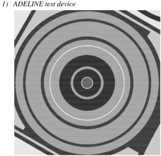
1) ADELINE test device
Fig. 2. Radial cross section of the ADELINE test device.
The ADELINE test device, presented in Fig. 2, is dedicated to the study of clad failure for fuel pins from all LWR (Light-Water Reactor) technologies. It is located on a displacement system in the reflector and hosts a single fuel rod (60-cm-tall fissile stack) in its center. The fuel rod is cooled down by a pressurized water loop contained by a pressure channel made of zirconium alloy. The test device consists of several zirconium-alloy shields, separated by helium or water gaps, for a total diameter of approximately 11 cm. Sizing of the thickness of each gamma shield is crucial to attenuate the incident photon flux, to reduce the temperature expected in the pressure channel and to ensure good material strength.
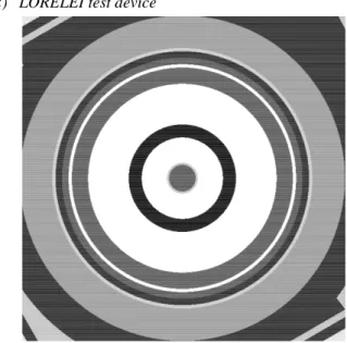
2) LORELEI test device
Fig. 3. Radial cross section of the LORELEI test device.
The LORELEI test device, presented in Fig. 3, is dedicated to the study of LWR-type fuel rods under loss-of-coolant-accident (LOCA) conditions. It is located on a displacement system and hosts a single fuel rod (60-cm-tall fissile stack) in its center. The fuel rod is contained in a pressurized water loop (which can quickly be emptied and filled with gas in order to simulate the dry-out phase of a LOCA transient) with a stainless-steel pressure channel. The device is made of an outer gamma shield in zirconium alloy, a 1-mm hafnium shield, a water gap, 2 stainless-steel tubes separated by a helium gap and an electrical heater (black ring surrounding the fuel rod in Fig. 3), for a total diameter of about 10 cm.
1) CALIPSO test device
Fig. 4. Radial cross section of 3 CALIPSO test devices.
Fig. 4 presents the radial cross section of 3 CALIPSO test devices inserted in a cylindrical aluminum block. This block takes the place of a JHR fuel assembly in the core. The diameter of a CALIPSO device is approximately 3 cm.
The CALIPSO test device is dedicated to the in-core irradiation of material samples immersed in NaK
(sodium-potassium alloy). It is made of an outer and an inner stainless-steel tube, the inner tube separating the flow of ascending and descending NaK. In the center, 5 floors can each host 3 material samples. Fig. 4 is a cross-section through one of the floor: 3 samples (stainless-steel claddings of diameter ~8mm, filled with helium), and 3 smaller stainless-steel beam structures supporting the floors can be seen.
2) Aluminum chock
Fig. 5. Radial cross section of an aluminum chock.
Fig. 5 presents the radial cross section of an aluminum chock for displacement systems hosting MOLFI irradiation devices (MOLydebnum from FIssion). The chock is surrounded by water and is drilled so as to contain 5 water holes (diameter 9 mm) for a better cooling of the chock. The height and width of the chock are approximately 3 cm and 6 cm respectively.
B. Definitions of absorbed dose and KERMA
Very accurate definitions of KERMA and absorbed dose can be found in [3].
Heating is represented by the physical quantity called absorbed dose. It is intuitively defined as the energy that is imparted to matter under the form of ionizations, atomic excitations or collective vibrations of atoms. This quantity is defined for a material sample under an incident particle flux as the radiant energy entering the sample minus the radiant energy leaving the sample, corrected of the mass-energy conversions occurring in the sample and divided by the sample mass. This quantity can be calculated by Monte Carlo codes and necessitates the computationally-expensive tracking simulation of charged particles along with the transport of neutrons and photons. In practice, only transport of light charged particles (electrons and positrons) is simulated as transport of the other, heavier charged particles can be reasonably neglected due to their small ranges in material.
KERMA (Kinetic Energy Released per unit MAss) is a physical quantity which is often used as an estimator of absorbed dose. It is defined as the sum of the initial kinetic energies of all the charged particles liberated by uncharged ionizing radiation in a sample of matter, divided by the mass of the sample. KERMA is not equal to absorbed dose in general because the energy transfer from neutral particles to charged particles at one spot does not grant the energy deposition of these charged particles at the same spot. However, under given conditions, including the condition of
charged-particle equilibrium, KERMA is equal to absorbed dose. This is in general the case for homogenous material blocks with dimensions much greater than the range of electrons in the material. As absorbed dose, KERMA can be calculated with Monte Carlo codes, but, contrary to absorbed dose, KERMA only necessitates the transport of neutron and photon. As a consequence, KERMA determination requires less computing power than determination of absorbed dose.
In a heating calculation, conditions of equality between absorbed dose and KERMA should be carefully examined so as to avoid introducing bias due to discrepancies between absorbed dose and its estimator. This is especially true for heterogeneous objects made of different material slices whose thickness is not much greater than the range of electrons. This is the case for the 3 irradiation devices and the aluminum chock under study in this article.
C. Calculation methodology
Prompt-photon-heating calculations are carried out with TRIPOLI-4.9® Monte Carlo code developed at CEA. Two criticality calculations are conducted: one with neutron-photon transport for KERMA calculation and one with neutron-photon-electron-positron transport for absorbed-dose calculation. In each case, heating is calculated at the core midplane and about 5 billion particle histories are simulated to obtain sufficient statistical convergence.
In the absorbed-dose computation, energy range for simulations of charged-particle transport stretches from 2 MeV to 20 MeV in the whole core. Additional simulation of charged particles from 1 keV to 2 MeV is restricted to the volumes close to tally volumes so as to speed up calculations.
D. Results and analysis
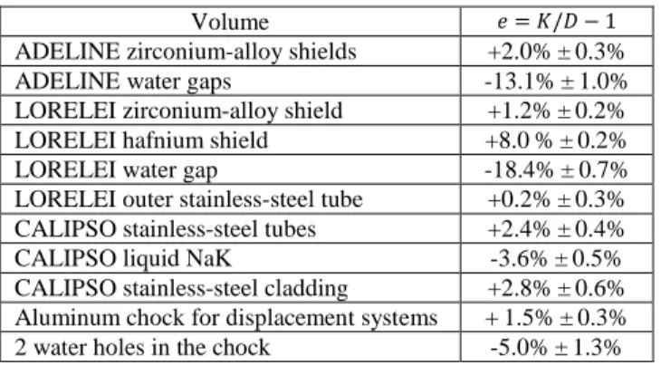
For this paragraph, we define 𝑒𝑒 as 𝑒𝑒 = 𝐾𝐾/𝐷𝐷 − 1, D being the absorbed dose and K the KERMA in a given volume. Table I presents the value of 𝑒𝑒 for a selection of volumes with its associated statistical uncertainty at one standard deviation.
TABLE I.KERMA/ ABSORBED DOSE COMPARISON IN JHR
Volume 𝑒𝑒 = 𝐾𝐾/𝐷𝐷 − 1 ADELINE zirconium-alloy shields +2.0%±0.3% ADELINE water gaps -13.1%±1.0% LORELEI zirconium-alloy shield +1.2%±0.2% LORELEI hafnium shield +8.0%±0.2% LORELEI water gap -18.4%±0.7% LORELEI outer stainless-steel tube +0.2%±0.3% CALIPSO stainless-steel tubes +2.4%±0.4% CALIPSO liquid NaK -3.6%±0.5% CALIPSO stainless-steel cladding +2.8%±0.6% Aluminum chock for displacement systems +1.5%±0.3% 2 water holes in the chock -5.0%±1.3%
We observe that KERMA tends to overestimate absorbed dose by a few percent in solids whereas it underestimates absorbed dose by a dozen percent in liquids. Greatest under- and overestimations are observed in the LORELEI test device, where a 1-mm hafnium shield (𝑒𝑒 = +8.0%) is located next to a 2-mm water gap (𝑒𝑒 = -18.4%).
These discrepancies between KERMA and absorbed dose are explained by the differences of density and atomic number between neighboring volumes. We take the example of a 1-mm hafnium shield located next to a 2-1-mm water gap. As hafnium is heavier (𝜌𝜌 ≈ 13 g.cm-3) and has a greater atomic number (Z = 72) than water, the number of electrons set in motion by photon interactions is much greater in the hafnium shield than in the water gap. The CSDA (Continuous Slowing-Down Approximation) range of 2-MeV electrons in hafnium being in the order of 1 mm, a non-negligible proportion of the electrons set in motion in the hafnium shield are energetic enough to leave the hafnium shield and to deposit their energy in the water gap. This energy which leaves the hafnium shield, is not compensated by the energies deposited in the hafnium shield from electrons coming from the water gap, as the photon interaction rate is much smaller in the water gap than in the hafnium shield. In the end, the energy transferred by photons to charged particles in the hafnium shield is greater than the energy that is actually deposited by charged particles in the hafnium shield, hence a KERMA greater than absorbed dose and a positive e value. To the contrary, the energy transferred by photons to charged particles in the water gap is smaller than the energy that is actually deposited by charged particles in the water gap, hence a KERMA smaller than absorbed dose and a negative e value.
This same reasoning is responsible for the KERMA / absorbed-dose discrepancy in stainless-steel, aluminum or zirconium-alloy volumes surrounded by water or NaK. But, as the density and atomic-number discrepancies are less pronounced in those cases than in the hafnium-water case, or as the geometry dimensions are much greater than electron range in matter, the imbalance between incident and outgoing charged particles is reduced for each volume, and so is the discrepancy between KERMA and absorbed dose.
We have quantified the order of magnitude of discrepancy between KERMA and absorbed dose for heating calculations in JHR. We now tackle in the next section the potential discrepancies between heating computations with different Monte Carlo codes.
III. MCNP/TRIPOLI-4.9® COMPARISON FOR ABSORBED
-DOSE AND KERMA CALCULATIONS
Reference [9] presented an interpretation with the TRIPOLI-4.9® code of photon-heating measurements carried out during the AMMON program [10] in the EOLE critical mock-up at Cadarache. One of the goals of the AMMON experiment consisted in validating the calculations of photon parameters for JHR. In this section, we compare the results of two different Monte Carlo codes on two geometrical configurations of interest for the above AMMON interpretation: a simplified JHR-representative configuration and a calibration configuration for photon-heating dosimeters used in the AMMON program. Beforehand, we deal with the calculation methodology used in this comparison and we describe the two geometrical configurations under study.
A. Calculation methodology 1) Codes and nuclear data
Calculations with TRIPOLI-4.9® used nuclear data from library CEAV5.1.1 processed on the basis of the JEFF3.1.1 data. Photon, electron and atomic relaxation data comes from the EPDL97 library. Neutron data were generated at 20°C temperature. Punctual neutron cross-sections were processed with the NJOY code [11] in the resolved energy range and probability tables were provided by the CALENDF code [12] in the unresolved energy range.
As for MCNP, calculations were first carried out with MCNP4c3 and used nuclear data from the library JEFF3.1.1, photon data from the library mcplib04 [13], [14] and electron data from the library el03 [15]. It was then verified that MCNP5 yields the same results as MCNP4c3 for the configurations we studied. Both mcplib04 and el03 are based on the EPDL97 library. Neutron data were generated at 20°C temperature. Punctual neutron sections in the resolved energy range and probability tables in the unresolved energy range were processed with the NJOY code.
2) KERMA calculation
For KERMA calculations, charged-particle transport was not simulated. Neutron and photon KERMA were computed with MCNP using the “F6:N” and “F6:P” tallies and with TRIPOLI-4.9® using the “DEPOSITED_ENERGY” scores for neutrons and photons, respectively.
It should be noted that TRIPOLI-4.9® does not simulate bremsstrahlung (or Thick-Target Bremsstrahlung – TTB) when charged particles are not transported. Consequently, the TTB option of MCNP was deactivated (option “phys:p j 1”) so as to allow comparison of photon KERMA between the two codes.
3) Absorbed-dose calculation
For absorbed-dose calculations, charged-particle transport was activated. Absorbed dose was computed with MCNP using the “*F8:P,E” tally and with TRIPOLI-4.9® using the sum of “DEPOSITED_ENERGY” scores for photon, electron and positron.
As for the electromagnetic-shower simulation, both codes take into account the transport of photon and electrons, the production of photons and knock-on electrons by electrons, the production of photons by electron-positron annihilation and by atomic fluorescence. Positrons are transported by both codes but MCNP uses identical physics for transport of electrons and positron whereas TRIPOLI-4.9® distinguishes electron and positron physics. All the electromagnetic-shower options by default were used for MCNP calculations. For TRIPOLI-4.9® calculations, one computation with all the options by default and one computation with the so-called option “ELECTRON_TOTAL_STOPPING_POWER” (ETSP) were done. The former corresponds to a simulation where TRIPOLI-4.9® distinguishes soft collisions and hard collisions of electrons and positrons whereas the latter ETSP option activates the Continuous-Slowing Down Approximation (CSDA) for electron-positron transport:
energy losses of electrons due to inelastic collisions are continuous and bremsstrahlung photons / knock-on electrons are produced independently. The ETSP option of TRIPOLI-4.9® corresponds to the default mode of MCNP.
More details about the electromagnetic-shower implementation in TRIPOLI-4.9® and MCNP can be found in [16], [17].
B. Geometrical configurations
Two simple calculation configurations were studied: a JHR assembly-cell and a heating-dosimeter calibration configuration. Special care was put on the modelling of these configurations so as to get exactly the same geometry with the two codes and to avoid introduction of calculation bias due to geometrical discrepancies. Simple geometrical configurations were therefore chosen so as to make this task easier.
1) JHR-assembly cell
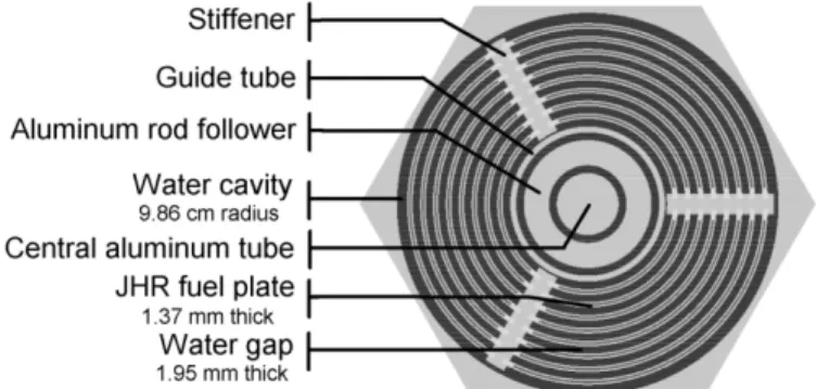
The first geometry under study is a 2D-JHR-assembly cell.
Fig. 6. Radial cross section of the JHR-assembly cell.
Fig. 6 presents a view of the JHR-assembly cell. The assembly is enclosed in a regular hexagonal cell in aluminum with side length equal to 7.21 cm. Reflection boundary conditions are defined axially and radially. The JHR assembly is made of 24 curved fuel plates, divided into three 120°-sectors separated by aluminum stiffeners. Fuel is U3Si2-Al with 20% 235U enrichment.
Reactivity, fission rate in the 24 fuel plates and absorbed-dose in the central aluminum tube are determined with a criticality neutron-photon-electron MCNP calculation and a criticality neutron-photon-electron-positron TRIPOLI-4.9® calculation. To speed-up calculations, “elpt” option of MCNP and “VOLENERCUT” option of TRIPOLI-4.9® were used to define 2-MeV energy cut-off for the transport simulation of charged particles in cells whose distance from the central aluminum tube is greater than the range of 2-MeV electrons in aluminum.
Neutron and photon KERMA in the central volumes are determined with a criticality neutron-photon calculation for both codes.
2) Photon-heating-dosimeter calibration configuration
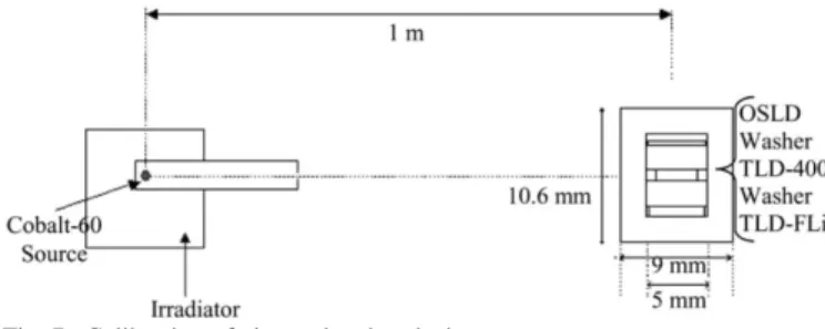
The second geometry under study is a calibration configuration for photon-heating dosimeters used in the AMMON program. This configuration is presented in Fig. 7.
Fig. 7. Calibration of photon-heating dosimeters
Three dosimeters are irradiated in an aluminum pillbox placed 1 m far from a standard punctual 60Co source located on the axial pillbox midplane. The dosimeters consist of an Al2O3:C OSLD (Optically-Stimulated Luminescent Dosimeter) and 2 TLDs (Thermo-Luminescent Detectors): a CaF2:Mn TLD-400 and a FLi:Mg,Na PTL-717. The dosimeters are very small, with a size of a few mm, and are separated by aluminum washers of height 2 mm.
Absorbed dose in the 3 dosimeters is determined with a shielding photon-electron MCNP calculation and a shielding photon-electron-positron TRIPOLI-4.9® calculation. KERMA is determined in the dosimeters with a shielding photon calculation for both codes. The photon source is biased in the cone direction of the detector so as to improve statistical convergence.
C. Results and analysis
The results of the comparison of KERMA calculations and absorbed-dose calculations in the calibration configuration, reactivity and fission rate calculations, KERMA calculations and absorbed-dose calculations in the JHR-assembly cell are presented in Table II, Table III, Table IV, Table V and Table VI, respectively. The uncertainty corresponds to the statistical uncertainty at one standard deviation.
TABLE II.MNCP/TRIPOLI-4.9® COMPARISON OF PHOTON KERMA IN THE CALIBRATION CONFIGURATION MCNP TRIPOLI4.9® − 1 OSLD +0.04% ± 0.14% TLD-400 +0.00% ± 0.07% PTL-717 +0.02% ± 0.06% Air surrounding the pillbox -0.10% ± 0.05%
TABLE III.MNCP/TRIPOLI-4.9® COMPARISON OF ABSORBED DOSE IN THE CALIBRATION CONFIGURATION T4.9 “ETSP” T4.9 “default” − 1 MCNP “default” T4.9 “default” − 1 OSLD -0.03% ± 0.05% +2.1% ± 0.2% TLD-400 +0.05% ± 0.04% +1.3% ± 0.2% PTL-717 +0.04% ± 0.03% +2.4% ± 0.1%
TABLE IV.MNCP/TRIPOLI-4.9® COMPARISON OF NEUTRON PARAMETERS IN THE JHR-ASSEMBLY CELL
Reactivity :
MCNP − TRIPOLI4.9® +10 pcm ± 10 pcm Total fission rate :
MCNP TRIPOLI4.9 ® − 1
-0.03% ± 0.05%
TABLE V.MNCP5/TRIPOLI-4.9® COMPARISON OF KERMA IN THE JHR-ASSEMBLY CELL MCNP TRIPOLI4.9® − 1 Neutron KERMA Photon KERMA Central aluminum tube -0.1% ± 0.2% +0.9% ± 0.1% Aluminum rod follower -0.1% ± 0.1% +1.0% ± 0.1% Guide tube +0.1% ± 0.1% +1.3% ± 0.1%
TABLE VI.MNCP5/TRIPOLI-4.9® COMPARISON OF ABSORBED DOSE IN THE
JHR-ASSEMBLY CELL T4.9 “ETSP” T4.9 “default” − 1 MCNP “default” T4.9 “default” − 1 Central aluminum tube +0.1% ± 0.1% +3.4% ± 0.3%
We first focus on the calibration configuration. As can be seen in Table II, there is no difference for the photon KERMA calculated by MCNP and TRIPOLI4.9® in the calibration configuration. This confirms in hindsight that the geometry of the calibration configuration (as described in input files) and the photon-transport data are identical for the two codes. Looking now at Table III, we find no difference for absorbed-dose values calculated with TRIPOLI-4.9® in default and ETSP mode, although electron tracking is more refined in the default calculation than in the ETSP calculation. To the contrary, there are discrepancies ranging from +1.3% to +2.4% between absorbed-dose values calculated by TRIPOLI-4.9® and MCNP. Geometry and photon-transport data cannot account for these discrepancies and electron data were taken from the same EPDL97 library for both codes. Therefore, the discrepancies that we observe should be linked to differences in electromagnetic-shower models and their implementation between the two codes, as such differences directly affect the way charged particles are transported and deposit their energies in the simulation.
We now focus on the JHR assembly cell. As can be seen in Table IV and Table V, there is no significant difference for reactivity, fission rate and neutron KERMA values determined with the two codes. This confirms in hindsight that the assembly-cell geometry and neutron-transport data are identical for the two codes. Nevertheless, we observe in Table
V a 1% discrepancy between photon KERMA values calculated by MCNP and TRIPOLI4.9®. Geometry, neutron-transport data and photon neutron-transport-data cannot account for this discrepancy. Among the remaining possibilities, this 1% discrepancy could be due to a slight difference of processing between the two codes for gamma-production data by neutron interactions (for instance, differences of processing for gamma-emission-spectrum interpolation).
Finally, we observe no difference in Table VI between the absorbed-dose values calculated by TRIPOLI-4.9® (default mode and ETSP mode) in the central aluminum tube of the JHR assembly cell. This was already the case for the calibration configuration. It might indicate that CSDA for charged-particle transport is good enough for the absorbed-dose calculations in the configurations we studied (meaning that a more refined simulation of charged-particle transport does not bring a significant change for the absorbed-dose calculations in these configurations). To the contrary, a 3% discrepancy can be seen in Table VI between absorbed-dose calculations with TRIPOLI-4.9® and MCNP. As mentioned above, geometry, neutron-transport data, photon-transport data and electron data cannot account for this 3% discrepancy. The 1% difference in photon KERMA we observed earlier in Table V partially explains the 3% discrepancy. The last 2% remaining should be linked to differences in electromagnetic-shower models and their implementation between the two codes.
D. Impact on the AMMON interpretation
We presented in [9] an interpretation with the TRIPOLI-4.9® code of photon-heating measurements carried out with TLDs and OSLDs in the AMMON experiment conducted in the critical mock-up EOLE of CEA Cadarache. We analyze in this section to what extent the Calculation / Experiment (C/E) values obtained in [9] would change if the interpretation was conducted with MCNP instead of TRIPOLI-4.9®.
Table VI shows that an absorbed-dose value calculated by MCNP in a JHR-representative geometry is approximately 3% greater than the value calculated by TRIPOLI-4.9®. We therefore consider that the net effect on the calculated values C would be a 3% increase.
We now study the impact on the measured values E. The values of absorbed dose in dosimeters 𝐷𝐷𝑇𝑇𝑇𝑇𝑇𝑇 and of air KERMA 𝐾𝐾𝑎𝑎𝑎𝑎𝑎𝑎 in the calibration configuration presented in Section III.B.2) are used in the AMMON interpretation to define a correction factor 𝐹𝐹 = 𝐾𝐾𝑎𝑎𝑎𝑎𝑎𝑎⁄𝐷𝐷𝑇𝑇𝑇𝑇𝑇𝑇. Table II and Table III show that the calculation of this correction factor with MCNP leads to a decrease of 𝐹𝐹 from 1% to 2%. As raw heating measurements from the AMMON experiment are divided by the correction factor 𝐹𝐹 to yield corrected heating measurements, the net effect on the measured values E is an increase of 1% to 2%.
All in all, the variation on the AMMON (C/E) values would be an increase of 1% to 2%. This variation is small with regards to the experimental and statistical uncertainties associated with these (C/E) values (mostly, the total uncertainty amounts to 4% to 7% at one standard deviation).
There is therefore a good agreement between MCNP and TRIPOLI-4.9® regarding the AMMON interpretation.
IV. CONCLUSION
By comparing KERMA and absorbed-dose calculations, we highlighted the effects of charged-particle transport for photon-heating calculations in chosen locations of JHR. These effects are significant for neighboring volumes with different density and atomic number and for volumes whose dimensions are smaller or comparable to electron range in matter. The discrepancies that we observe in JHR between absorbed dose and KERMA can reach up to 18%. It would be interesting to conduct the same study for other locations in the JHR, such as hafnium control rods cooled down by water (in the context of local-boiling safety study) or beryllium blocks in the reflector in aluminum casing (in the context of deformation-creep study).
We compared absorbed-dose and KERMA calculations with two different Monte Carlo codes, TRIPOLI-4.9® and MCNP. In a JHR-representative configuration, we found discrepancies in the order of 1% for photon KERMA calculations whereas an absorbed-dose discrepancy amounting to up to 3% has been highlighted. Those discrepancies are supposed linked to differences in the processing of gamma-production data by neutron interactions and to differences in electromagnetic-shower models and implementation. The observed discrepancies remain small in comparison of other typical sources of calculation uncertainty, such as nuclear data uncertainty. Agreement is therefore good between the two Monte Carlo codes for the configurations we studied. It would be interesting to compare these results with the PENELOPE Monte Carlo code [18], which is a reference code for electron and photon transport.
ACKNOWLEDGMENT
We thank B. Pouchin, C. Huot-Marchand and P. Siréta for their help concerning JHR modelling and technical data.
REFERENCES
[1] CEA. The JHR Jules Horowitz Reactor. [Online]. Available: http://www-cadarache.cea.fr/rjh/index.html. Retrieved 2015, March 23rd.
[2] G. Rimpault et al. Needs of accurate prompt and delayed gamma-spectrum and multiplicity for nuclear reactor designs. Physics Procedia. 2012; 31:3-12.
[3] International commission on radiation units and measurements. Fundamental quantities and units for ionizing radiations (revised). Oxford University Press; 2011, Report no. 85.
[4] E. Brun et al., “TRIPOLI-4, CEA, EDF and AREVA Reference Monte Carlo Code”, Proc. Int. Conf. SNA+MC 2013, Paris, France, 2013. [5] J.F. Briesmeister. MCNP-A general Monte Carlo N-particle transport
code. [Online]. Available: http://mcnp.lanl.gov. Retrieved 2014, Sep 16. [6] A. Santamarina et al. JEFF report : the JEFF3.1.1 nuclear data library.
Nuclear Energy Agency; 2009, Report no.22.
[7] D.E. Cullen, J.H. Hubbell, L. Kissel. EPDL97: the evaluated photon data library, 1997 version. Lawrence Livermore National Laboratory; 1997, UCRL-LR-50400, Vol. 6, Rev. 5.
[8] C. Blandin et al., “Fuel and material irradiation hosting systems in the Jules Horowitz Reactor,” in Proc. Int. Conf. IGORR 15, Daejeon, South Korea, Oct. 2013.
[9] M. Lemaire et al., “Experimental validation of photon-heating calculation for the Jules Horowitz Reactor,” Nuclear Instrumentation and Methods in Physics Research A 780 pp 68-80, 2015.
[10] J.C.Klein et al., “AMMON: an experimental program in the EOLE critical facility for the validation of the Jules Horowitz Reactor neutron and photon HORUS3D calculation scheme, ” in Proc. Int. Conf. IGORR 12, Beijing, China, Oct. 2009.
[11] R.E. MacFarlane et al., “ NJOY, a code system for producing pointwise and multigroup neutron and photon cross-sections for ENDF/B evaluated nuclear data,” Los Alamos National Laboratory, LA-UR-89-2057, 1994.
[12] J.C Sublet, P. Ribon, “A probability-table-based cross-section processing system: CALENDF - 2001,” Journ. of Nuclear Science and Technology, 39:sup2, 856-859, 2002.
[13] M.C. White, “Photoatomic Data Library MCPLIB04: A New Photoatomic Library Based On Data from ENDF/B-VI Release 8,” Los Alamos National Laboratory, LA-UR-03-1019, 2003.
[14] M.C. White, “Further notes on MCPLIB03/04 and new MCPLIB63/84 Compton broadening data for all versions of MCNP5,” Los Alamos National Laboratory, LA-UR-12-00018, 2012.
[15] D.E. Cullen, S.T. Perkins, S.M. Seltzer, "Tables and Graphs of Electron Interaction Cross 10 eV to 100 GeV Derived from the LLNL Evaluated Electron Data Library (EEDL), Z = 1 - 100," Lawrence Livermore National Laboratory, UCRL-50400, Vol. 31, Nov. 1991.
[16] Y. Pénéliau, “Electron Photon Shower Simulation in TRIPOLI-4 Monte Carlo Code,” in Proc. Int. Conf Monte Carlo 2000, Lisbon, Portugal, 23–26 Oct. 2000.
[17] X-5 Monte Carlo team, “MCNP — A General Monte Carlo N-Particle Transport Code, Version 5. Volume I: Overview and Theory,” Los Alamos National Laboratory, LA-UR-03-1987, 2005.
[18] F. Salvat, J.M. Fernández-Varea, J. Sempau, “PENELOPE-2011: A Code System for Monte Carlo Simulation of Electron and Photon Transport”, OECD Nuclear Energy Agency, Issy-les-Moulineaux, OECD NEA Data Bank/NSC DOC(2011)/5, 2011.