1
High temperature oxidation of two- and three-dimensional hafnium
carbide and silicon carbide coatings
By
C. Verdona*; O. Szwedeka; A. Allemanda,b; S. Jacquesa; Y. Le Petitcorpsa, P. Davidb
aUniversité Bordeaux, LCTS, UMR5801, F-33600 Pessac France
bCEA, DAM, Le Ripault F-37260 Monts France
Journal of the European Ceramic Society, 34(4), 879–887 (2014)
DOI : https://doi.org/10.1016/j.jeurceramsoc.2013.10.019
2
High temperature oxidation of two- and three-dimensional hafnium
carbide and silicon carbide coatings
C. Verdona*; O. Szwedeka; A. Allemanda,b; S. Jacquesa; Y. Le Petitcorpsa, P. Davidb
aUniversité Bordeaux, LCTS, UMR5801, F-33600 Pessac France
bCEA, DAM, Le Ripault F-37260 Monts France
*verdon@lcts.u-bordeaux1.fr Phone : +335 56 84 47 30 Fax: +335 56 84 12 25
Keywords UHTC; oxidation; carbides; refractories; Hafnium Abstract
The difficulty in using above 2000°C in an oxidizing atmosphere C/C composites as structural components is their poor life time. The solution proposed here consisted in combining two refractory carbides, hafnium and silicon carbides, in coating with a complex architecture, named a three dimensional coating, over a C/C substrate. Such a coating protects the C/C composite at 2050°C under air. The oxidation of the coating leads to the formation of a SixOyHfz hafnium-containing silicate liquid, combined with HfO2(s). This liquid limits oxygen
diffusion more than pure SiO2 does, so it is a better protection against oxidation.
Furthermore, HfO2(s) acts as a grip holding SixOyHfz in place. From these results, an
oxidation mechanism is proposed and discussed.
1. Introduction
C/C composites (carbon fibers embedded in carbon matrices) exhibit a poor lifetime under an oxidizing atmosphere; the carbon fiber starts to be oxidized under air at a temperature of 400°C [1]. In order to protect composites from oxidation, many coatings made of Ultra High Temperature Ceramics (UHTCs) have been tested. It is known that they can resist to extreme heat flux and high mechanical stresses [2]. For example, Clougherty et al. have studied oxidation of diborides HfB2, ZrB2 TiB2 and a mixture of HfB2-SiC [3]. The oxidation
mechanism model of these coatings have been studied by Parthasarathy et al. [4] who proposed a mechanistic model that simulates the oxidation behavior of the diborides in the temperature range of 1000°C to 1800°C. Among the studied carbide-based coatings, an HfC/SiC dual layer developed by Wunder et al. has shown promising oxidation protection for PyC-coated C/C composites at temperatures up to 1450°C [5]. Besides, Baklanova et al. highlighted the fact that HfC/SiC-coated carbon fibers exhibit a higher oxidation resistance at 2000°C than the initial HfC-coated carbon fibers [6]. Wang et al. have determined that SiC/HfC/SiC is an interesting coating to protect carbon/carbon composites with a mass loss of only 2.3% after oxidation at 1500°C. They also have characterized a stable glassy phase composed by HfSiO4 which could protect C/C composites [7].
In the present work, two carbides were selected. SiC has been used in many works; it allows protection against oxidation until 1650°C by forming a SiO2 layer [8]. It is the best diffusion
barrier against oxidation below 1400°C [1]. But, above 1650°C under air the oxidation becomes active and all the protection is lost. In spite of a high melting point (3890°C), HfC is actively oxidized at low temperature, from 400 – 500°C, forming porous HfO2. Its oxidation
3
advantage of being refractory with a melting point of 2810°C and has a lower vapor pressure than SiO2 [4]. The aim of the present study was to combine theses two carbides to find a
synergetic effect: a refractory coating that allows a good oxidation resistance. Two kinds of samples, monolithic HfC/SiC sintered samples and C/C composites with (HfC/SiC)n
multilayer coatings, were prepared [10] [11] and then characterized after high temperature oxidation. This characterization of the oxidized samples allowed us to propose an oxidation mechanism.
2. Experimental procedure 2.1. Monolithic sample
The monolithic freestanding sample (named sample A, Table 1) was prepared by following two steps.
Table 1: Sample characteristics overview
Sample A Sample B Sample C
Sample kind Monolithic 2D (10 layers) 3D + 2D (10 layers) Sample composition HfC/SiC C/C substrate + (HfC/SiC)5 C/C substrate + (HfC/SiC)5 Way of synthesis FBCVD + SPS CVD CVD
HfC powder with a d50 =35°µm, was first coated with 1 µm of SiC by fluidized bed chemical
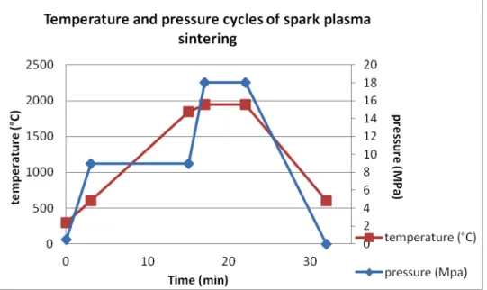
vapor deposition (FBCVD). This work was supplied externally to Lifco industry. Then this core-shell powder was sintered by spark plasma sintering (SPS). Sintering parameters were: temperature of 1950°C, pressure of 18 MPa and dwell time of 5 minutes, following cycles presented in Fig. 1.
Fig. 1: pressure and temperature cycles of spark plasma sintering
The machine was a Dr Sinter 2080 from Syntex (Japan). The final sample was a cylinder with a diameter of 12 mm and a thickness of 6 mm.
4
The other kinds of samples, (sample B and sample C, Table 1) consisted in (SiC/HfC)n
multilayer coatings over C/C substrates by low pressure Chemical Vapor Deposition (CVD) at 1000°C and 5 kPa. Sample B and C have same size as sample A. The device used was composed of a hot-wall CVD reactor and a chlorinating device. HCl(g) reacted at 700°C with
metallic Hf(s) to form HfCl4(g) in the chlorinating device. The hafnium metal was an
electrolytic grade Hf(s) supplied by Areva. HfCl4(g) precursor was simultaneously injected with
argon as a carrier gas and reacts with CH4(g) and H2(g) in the CVD reactor to give HfC coating.
The SiC layers were classically made from methyltrichlorosilane and hydrogen. The MTS was supplied by Sigma Aldrich and its purity was superior to 97%.
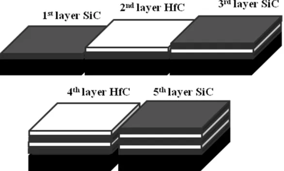
Sample B consisted of a classical bi-dimensional coating made of ten alternated layers of SiC and HfC, according to the Kaplan’s patent [12]. A structure scheme, corresponding to the five first layers, is presented by Fig. 2. The five last layers are identical to the five first one.
Fig. 2: structure scheme of the 5 first layers of sample B corresponding to 2D structure coating.
Sample C consisted of five alternated layers of HfC and SiC with a three-dimensional arrangement and another five alternated layers of HfC and SiC with a two-dimensional arrangement, according to our patent [11]. A structure scheme corresponding to the five first layers formation of the 3D structure is presented Fig. 3. The five last layers are identical to the five first sample B layers.
5 1stlayer SiC whiskers 2ndlayer HfC 3rdlayer SiC HfC 4thlayer SiC 5thlayer
Fig. 3: Structure scheme of the 5 first layers of sample C corresponding to 3D structure coating. 2.3. Oxidation test
The samples were oxidized under air in an arc image furnace at the CEA/Cesta center (Bordeaux, France). The furnace is composed by six Xenon arc lamps. These lamps are placed in the first focus of elliptical reflectors in order to concentrate emitted radiation at the second focus. The second focus of each reflector coincides in one place, corresponding to sample position. It allows adding six lamps energy on surface sample. The temperature of the center of the samples measured by a thermocouple reached 1600°C in 50 seconds and finally 2000°C in 200 seconds. Then samples are kept few seconds at 2000°C Seven samples were oxidized. The temperature profile is presented by the Fig. 4. This time and temperature of oxidation test correspond to sample B coating destruction. The center of the surface sample was the most affected area due to a temperature gradient between the centre and the side of surface sample.
6 2.4. Characterization
The crystal structure of the sample surface was identified by X-ray diffraction (XRD) with a Diffractometer D8 advance Bruker (CuKα). Before and after oxidation test, specimens were mounted in resin, cut and polished in order to carry out morphological observation by scanning electron microscopy (SEM) with a SEM FEI Quanta 400 FEG using backscattered electron (BSE) and secondary electron (SE) detectors under an accelerating voltage less than 20 kV. Qualitative chemical analyses were also performed in the microscope by energy dispersive X-ray spectroscopy (EDS). The composition of each layer after oxidation was determined more precisely by electron probe microanalysis (EPMA) with an EPMA CAMECA SX100. Raman spectroscopy analyses was realized with a Horiba Jobin-Yvon, Labram HR spectrometer (λHe-Ne = 632.8 nm)
3. Results
3.1. Monolithic sample
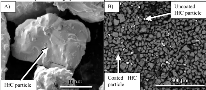
The Fig. 5 A) presents an HfC particle before FBCVD. The Fig. 5 B) corresponds to a back scattered electron picture of HfC coated powder, coating is uniform almost every particles are coated. Coated particles are grey and uncoated particles are white.
Fig. 5: A) morphology of the HfC particle before FBCVD. B) Back scattered electron of HfC powder coated by SiC.
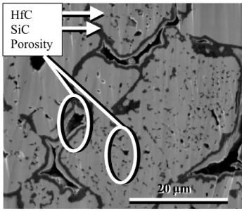
During spark plasma sintering bonding between particles of core-shell powder is created. Particles are welded together into a monolithic sample. Fig. 6 presents a polish cross section of a monolithic sample before oxidation (sample A). A homogeneous SiC layer is visible around particles. The sample polishing (made by cross-polisher) allows particles component to refill a part of porosities between particles and create a thin white layer inside it.
300 µm 10 µm HfC particle 10 µm A) Coated HfC particle 300 µm B) Uncoated HfC particle
7
Fig. 6: polished section of monolithic sample observed by SEM.
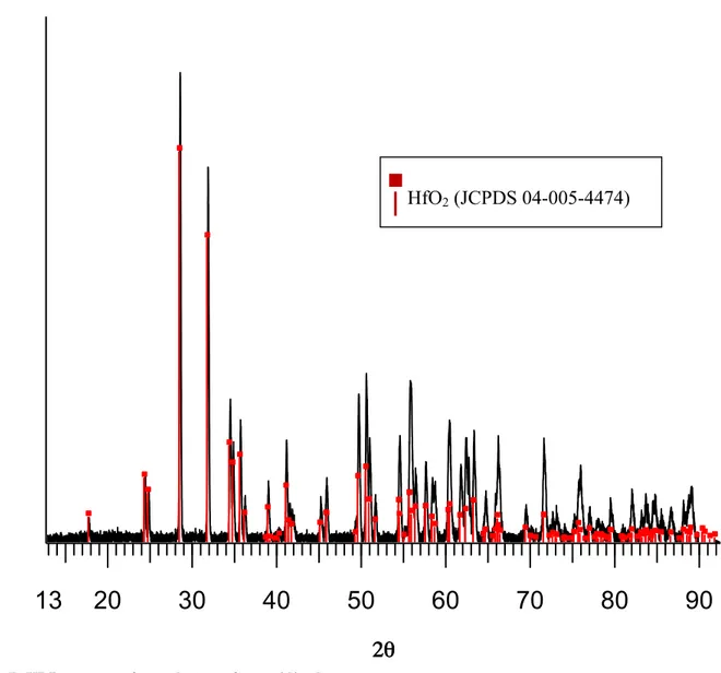
Sample A is the most convenient to investigate the oxidation behavior because its important thickness allows all the oxidation steps to be separated. The sample has not been affected in the bulk by oxidation. After oxidation, following the path exhibited in paragraph 2.3 oxidation test, the sample is studied by XRD.
The analysis of the sample surface gives a pattern typical of crystallized oxide HfO2(s)
corresponding to the JCPDS card N°04-005-4474 (Fig. 7). HfO2 is the only detected phase.
The pattern of the untouched material is not visible under this thick oxide seals.
20 µm
20 µm HfC
SiC Porosity
8
04-005-4474 (I) - Hafnium Oxide - HfO2 - Y: 74.53 % - d x by: 1. - WL: 1.5406 - Monoclinic - a 5.11560 - b 5.17220 - c 5.29480 - alpha 90.000 - bet tir1std - Step: 0.0092 ° - Step time: 53.4 s - 2-Theta: 10.0000 ° - Divergence slit: V4 - Antiscatter slit: 0.499 °
In
te
nsity (a.u.
)
2θ
13
20
30
40
50
60
70
80
90
Fig. 7: XRD pattern of sample A surface oxidized.
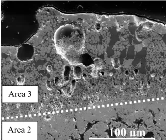
The sample is composed of 3 areas observed by scanning electron microscopy in Fig. 8 a). Area 1 is undamaged and exhibits a thickness of 59 mm, Fig. 8 b). It is composed of HfC grains with SiC at HfC grains boundary, no change of grains sizes can be highlighted. Few porosities are visible. Area 2, Fig. 8 c) is highly porous and is around 100 µm thick. Silicon could not be found in Area 2. Area 3, at the outer surface, is composed of an oxide skeleton in a glassy continuous phase and is around 250 µm thick, Fig 8 d).
9
Fig. 8: SE SEM observation of sample A after oxidation at 2000°C and quenched under air: overview image with the 3 areas that compose this sample (a), example of enlarged view ofarea 1 composed by 2 carbides (b), example of enlarge view of area 2 composed by HfO2(s) (c), example of enlarge view of area 3 composed of two oxides (HfO2 and SixOyHfz) (d).
EDS analyses show that the glassy phase consists mainly of silicon with oxygen and some hafnium (less than 5% atomic) according to the formula SixOyHfz. The oxide skeleton is
composed of hafnium and oxygen in proportion of HfO2, confirmed by EPMA. The oxidation
area total thickness is around 350 µm.
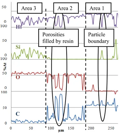
Fig.°9 corresponds to component quantities observed during EPMA analyze. The Table II lists average quantity of element detected in each area. The hafnium atomic composition determined by EPMA is quasi-constant on the entire sample (Fig. 9 and Table II) aside from holes and particle boundary. The silicon is present in areas 1 and 3; area 2 is silicon-free. The atomic percent of carbon decreases from area 1 to area 3. In area 2, carbon peaks correspond to porosity filed with carbon resin. In area 3, carbon is no more detected. In reverse, the oxygen atomic content increases from the inside to the outside of the sample (Fig. 9 and Table II).
400µm
Area 3 Area 2 Area 1 HfO2(s) SixOyHfz (a) (b)20µm
400µm
EPMA analyze50µm
50µm
50µm
(c) (d) HfO2(s) SiC(s) HfC(s)50µm
20µm
Porosities filled by resin10 Fig. 9: EPMA analyses of sample A after oxidation. Table II: average composition of sample areas. average composition (%at) element area 3 area 2 area 1
Hf 21,1 27,6 33,2
Si 15,2 0,5 6,7
O 56,6 41,4 2,1
C 7,0 30,5 58,5
The compositions of the three areas can be deduced from this analysis. Area 1 is a non affected part composed of HfC/SiC grains. Area 2 is made of porous HfO2(s). Area 3 is
composed of HfO2(s) skeleton combined with amorphous SixOyHfz (Fig. 8 d). The SixOyHfz
glass is, of course, not detected by XRD because of its amorphous structure (Fig. 7).
The microstructure of the oxidized sample A exhibits the presence of holes in area 3 which results from gas formation in large quantities (Fig. 10) and accumulation.
Area 3 Hf Si O C Particle boundary Porosities filled by resin Area 2 Area 1
11
Fig. 10: SE SEM observation of porosities at the surface of the oxidized sample A.
A particularity of the Area 3 is Hf containing recrystallized parts forming dendrites, more visible in important glassy phase volume. Dendrites are exposed in Fig.°11. The Fig.°11 (a) corresponds to an axial view of dendrites. Fig.°11 (b) corresponds to a perpendicular view of the dendrites.
Fig.°11: View of area 3 containing dendrites made by recrystallization of a Hf containing compound. Fig.°11 (a) corresponds to an axial view of dendrites. Fig.°11 (b) corresponds to a perpendicular view of dendrites.
Raman spectroscopy analyses results are presented in Fig.°12. A spectrum is first realized on a HfO2(s) skeleton and compare to the spectrum exposed by S. N. Tkachev [13] A second
spectrum is realized on the phase composed by the glassy phase and dendrites. Results are exposed in Fig.°12. The spectrum shows an amorphous part corresponding to the glassy phase and a crystallized part corresponding to HfO2(s) spectrum. Consequently, the Hf containing
recrystallized component is HfO2(s)
100 µm
Area 3 Area 2 5 µm 50 µm 5 µm 50 µm(a) HfO2(s) HfO2(s) (b)
recrystallized
HfO2(s)
12
Figure 12: Raman spectrum. a) Curve corresponding to glassy phase with dendrites analyses. b) Curve corresponding to HfO2(s) in area 3 formed during oxidation analyses.
3.2. CVD Coatings on C/C composites 3.2.1. Sample B.
Fig. 13 presents a sample B-type coating over a C/C substrate with three layers of SiC in dark grey and two layers of HfC in light grey. Unlike Fig. 13, sample B has actually a total of ten alternated layers of HfC and SiC, the coating is 20 µm thick (not shown here).
Fig. 13: SE SEM image of a sample B-type coating, made by CVD. This sample consists of a two-dimensional multilayer coating on C/C substrate only five layers are shown on this picture.
Fig. 14 presents the microstructure after oxidation at 2000°C under air after 200s of sample B (same oxidation step as sample A and C). Neither residual carbide multilayer coating nor oxide layers are visible. The C/C substrate is naked and only slightly damaged at the surface. An oxide scale has certainty protected this sample. But a spelling of the superficial oxidized layer occurs HfC SiC Substrate resin
10 µm
10 µm
a) b) a) b)13
Fig. 14: SE SEM picture of a sample initially coated with a two-dimensional coating, like sample B, after oxidation in air at 2050°C. No coating is still visible it delaminated. 3.2.2. Sample C.
Fig. 15 presents an example of sample C before oxidation with its 10 layers coating. The coating is 40 µm thick. Two parts are visible, the five first layers forming the three-dimensional structure where the sub-layers are concentrically arranged around SiC whiskers. This structure was detailed on the paragraph 2.2 multilayer coating made by CVD. Over this structure a two-dimensional part made of five layers is visible [11].
Fig. 15: SE SEM images of sample C before oxidation.
After oxidation (following the path exhibited in paragraph 2.3 oxidation test) of sample C, an oxidized coating layers are still observed on the C/C (Fig. 16). Fig. 16 a) presents the center of the sample surface, where the coating has been most severely oxidized. Wide cracks have been filled with mounting resin. At the outer surface, a SixOyHfz glass is evidenced by
chemical analysis, as in sample A. Holes created by gas released are also observed. The initial two-dimensional (SiC/HfC)n multilayer coatings have been replaced by some HfO2(s) structure
broken into disorganized pieces. SiC seems to have disappeared; only some residuals parts are visible in Fig. 16. The three-dimensional and undamaged structure of the coating is still visible close to the substrate. In place of the initial three-dimensional coating close to the
50 µm
resin Cracks = Oxidized area No coating is still visible Damaged C/C substrate Undamaged C/C substrate 3D structure 2D structure SiC HfC SiC Outer surface 30 µm 30 µm14
substrate, the oxide mixture of HfO2(s) and SixOyHfz is also found but with a more refined
microstructure. The carbon/carbon substrate has begun to be locally damaged.
Fig. 16: BSE SEM images of the center (a) and the side (far from the spot impact) (b) of sample C exposed to oxidation in air at 2000°C.
Fig. 16 b) presents the side of the sample, where the coating is less damaged. The different behavior between the side and the centre of the sample surface can be explained by the temperature gradient. Under the outer SixOyHfz glass layer, evidenced by chemical analysis,
HfO2(s) sub-layers are found separated by wide cracks filled with mounting resin. This feature
evidences that SiC layers have undergone an active oxidation. The free spaces created becomes delamination zone between the sub-layers. Although cracked in some places, the oxide layers are more continuous than in Fig. 16 a) and retain the original shape of the two-dimensional HfC sub-layers that they replace. Some residuals SiC sub-layers are still present. Close to the substrate, the initial three-dimensional multilayer carbide coating is observed with its undamaged structure. The inner part of the coating is thus non-oxidized, SiC and HfC layers being intact.
From the studies of these samples, an oxidation mechanism can be proposed. The species found in sample C are the same as in sample A after oxidation. The hypothesis is that the mechanism of the monolithic sample oxidation and the one of the three-dimensional coating oxidation are very similar and involve the same chemical reactions.
4. Discussion:
4.1. Mechanism based on the monolithic sample behavior
Pure HfC begins to be oxidized above 500°C [9]. But in this study, HfC is combined with SiC. From 500°C to 1500°C, SiC is oxidized to SiO2 which is supposed to significantly
protect HfC from oxidation because SiO2(s) is the most effective oxygen barrier coating below
1500°C [1]. From room temperature to 1650°C the oxidation temperature rises in less than 100s which can be considered as very fast. Consequently, it is admitted that the SiO2 first
layers produced by SiC oxidation still protect HfC from O2 which did not have the time to
diffuse through the SiO2 layer.
resin SixOyHfz Holes HfO2(cr) SiC Cracks filled with resin Intact HfC and SiC Substrate
100µm
a) b)40µm
40µm
15
Above 1700°C, in agreement with the HfO2 – SiO2 binary diagram (Fig. 17) [14] [15], the
suggested mechanism of sample A oxidation, presented in Fig. 18, consists of 3 steps which, once initiated, can take place simultaneously.
First, HfC and SiC are oxidized according to reactions R1 and R4 near the outer surface and according to reactions R2 and R5 deeper where oxygen partial pressure is lower. These reactions release gases (CO(g), CO2(g) and SiO(g)). At the surface, SiO(g) released from the
inner part of the sample is oxidized according to R3 to form a condensed and liquid layer of SiO2(l) because of higher oxygen partial pressure [16]. This liquid tends to seal the pores and
cracks of the outer scale. Moreover CO(g) and CO2(g) create bubbles in the outer liquid oxide
layer as shown in Fig.10 and Fig.16 a) (where holes are observed) and cracks in the HfO2(s)
structure in the deeper and outer parts as shown in Fig. 16. The phenomena involved in the deeper part correspond to the formation of area 2 in the schematic representation (Fig. 18). Finally, SiO2(l) dissolves a part of HfO2(s) and reacts with it to form a hafnium-containing
silicate liquid, SixOyHfz(l), according to R6 and the binary diagram of HfO2-SiO2 that
highlights the coexistence at 2000°C of HfO2(s) with a silicon-rich liquid (SiO2 90%mol.; HfO2
10%mol.) (Fig. 18) [14] [15]. The liquid results in a SixOyHfz hafnium-containing silicate glass
after quenching leading to the formation of area 3 with the remaining HfO2(s) that was not
dissolved by SiO2(l) and forms a skeleton. Hence, hafnium is always found by EDS analyses.
But, contrary to Wang et al. [7] the HfSiO4 glassy phase has not been observed here. This
glassy phase is formed during a longer oxidation time at lower temperature (1500°C and 66 hours).
However analyses of recrystallised dendrites shows that they are composed by HfO2(s). The
quantity of Hf inside glassy phase is inferior to 5% atomic. It corresponds in the binary diagram, Fig.°18, to a mixt Hf02-SiO2 with respectively 5 and 95 % atomic at least. At
2000°C this composition is completely liquid and corresponds to SixOyHfz. When the
oxidation test is finished the glassy phase is cooled and HfO2(s) recrystallized. R1: SiC + 3/2O2 è CO2(g) + SiO(g)
R2: SiC +1/2O2 è CO(g) + SiO(g)
R3: SiO(g) + 1/2O2 è SiO2(l)
R4: HfC + 2O2 è HfO2(cr) + CO2(g)
R5: HfC + O2 è HfO2(cr) + CO(g)
16 Fig. 17: HfO2 - SiO2 binary diagram [13]
Fig. 18: schematic representation of the oxidation mechanism of the monolithic sample. Oxidation
17
From this, it is proposed that the effective protection against oxidation is based on the formation of the SixOyHfz hafnium-containing silicate liquid combined with the HfO2(cr)
skeleton.
As explained by Vogel, when a group 4 element, like hafnium, is added to SiO2(l) the
tendency to phase separation and immiscibility rises and so the viscosity η increases [17]. Opeka et al. [16] made the link between Vogel and the Stokes-Einstein relationship which shows that the oxygen diffusion coefficient through the liquid oxide is inversely proportional to the viscosity. Consequently, by adding Hafnium, the oxygen diffusion coefficient decreases and next sub-layers are better protected from oxidation than with pure SiO2(l). These authors
were the first to develop the concept of "phase separation as a controlling factor in the oxidation protection".
Furthermore, the HfO2(cr) skeleton acts as a grip holding the liquid SixOyHfz in place during
oxidation and so helps to protect next layers from further oxidation. Theses two points take a part in coating oxidation protective role. 4.2. Extrapolation of the mechanism for CVD samples
The behavior under oxidation of the monolithic sample A is used as a basis that can be extrapolated to the oxidation mechanism of CVD coated samples B and C.
In both samples B and C, the five exposed outer layers are two-dimensional. First, the most outer layer, made of SiC, is oxidized below 1500°C to form SiO2(l) according to R1, the
oxidation of SiC being passive [8]. When the temperature increases, the SiC oxidation becomes active and the SiO2(l) layer is ruptured by the produced gases. In the same time, the
oxygen diffuses through the ruptured SiO2(l) scale and reaches the deeper carbide sub-layers.
The oxidation mechanism should be then similar to the monolithic sample oxidation mechanism explained in paragraph 4.1 Mechanism based on the monolithic sample behavior. But as HfC and SiC have different coefficients of thermal expansion, the temperature increase induces delamination and cracks between the C/C substrate and the multilayer coating.
In the case of sample C, the initial deeper three-dimensional structure part is composed of concentric and interlocked carbide sub-layers that give a mechanical grip preventing delamination [18]. Silicon and hafnium carbide phases being kept in contact with each other; the oxidation mechanism can occur as described above for the monolithic sample A and so protects more effectively the C/C substrate.
Conclusion
A new protection against oxidation at very high temperature composed of hafnium and silicon carbides was realized by two synthesis ways. Its behavior under oxidation was studied with an arc image furnace. After oxidation under air at 2000°C the microstructure and composition of samples were characterized and a mechanism was proposed. Finally, the influence of the coating structure was studied and the advantage of the three-dimensional structure over the two-dimensional multilayer structure was highlighted. The oxidation mechanism took into account six reactions, two corresponding to SiC oxidation, two to HfC oxidation, one to an oxidation of SiO(g) when the oxygen partial pressure increases at the sample surface, and one
between HfO2(s) and SiO2(l) forming a hafnium-containing silicate glass in addition to the
unreacted HfO2(s), in agreement with the HfO2-SiO2 phase diagram.
The resistance against oxidation of samples mainly comes from the SixOyHfz liquid phase
which limits the oxygen diffusion better than pure SiO2. In addition, the three-dimensional
structure has three advantages. It allows the formation of HfO2(s) skeleton that acts as a grip
18
The three-dimensional structure with initial interlocked carbide sub-layers gives a mechanical grip between the C/C composite and the multilayer coating (ii). Moreover, it increases the exchange surface between the chemical compounds (iii). Complementary works are in progress specifically to assess the potential of other combinations of refractory carbides like tantalum carbide.
Acknowledgment
This work was support by the “Alternative Energies and Atomic Energy Commission” (CEA). We thank M. Lahaye of “the Center for characterization of advanced materials for chemical” (CeCAMA) for characterization of the layers and Prof. F. Rebillat to give us tracks to follow. References
[1] McKee DW. Oxidation Protection of Carbon Materials. In: Thrower PA, editor. Chemistry and physics of carbon, vol. 23. New York: Marcel Dekker; 1991. p. 173-232. [2] Paul A, Jayaseelan DD, Venugopal S, Zapata-Solvas E, Binner J, Vaidhyanathan B,Heaton A, Brown P, Lee WE. UHTC composites for hypersonic applications. Am Ceram Soc Bull 2012;91(1):22-8.(http://hdl.handle.net/2134/9676)
[3] Clougherty EV, Pober RL, Kaufman L. Synthesis of Oxidation Resistant Metal Diboride Composites. Trans Metall Soc AIME 1968;242:1077-82.
[4] Parthasarathy TA, Rapp RA, Opeka M, Kerans RJ. A model for the oxidation of ZrB2,
HfB2 and TiB2. Acta mater 2007;55:5999-6010. http://dx.doi.org/10.1016/j.actamat.2007.07.027
[5] Wunder V, Popovska N, Wegner A, Emig G. Arnold W. Multilayer coatings on CFC composites for high-temperature applications. Surf Coat Tech 1998;100-101:329-32 http://dx.doi.org/10.1016/S0257-8972(97)00643-9
[6] Baklanova NI, Zima TM, Boronin AI, Kosheev SV, Titov AT, Isaeva N.V, Grashenkov DV, Solntesev SS. Protective ceramic multilayer coatings for carbon fibers. Surf Coat Tech 2006;201:2313-19.
http://dx.doi.org/10.1016/j.surfcoat.2006.03.046
[7] Wang Y, Li H, Fu Q, Wu H, Yao D, Li H, SiC/HfC/SiC ablation resistant coating for Carbon/Carbon composites; Surf. Coat. Tech. 2012, 206, 3883-3887
http://dx.doi.org/10.1016/j.surfcoat.2012.03.039
[8] Strife JR, Sbeehan JE, Ceramic coating for carbon-carbon composites, Am. Ceram. Soc. Bull.1988, 67 (2) 369-374
[9] Shimada S, Inagaki M, Matsui K. Oxidation Kinetics of Hafnium Carbide in the temperature Range of 480°C to 600°C. J Am Ceram Soc 1992;75(10):2671-78. http://dx.doi.org/10.1111/j.1151-2916.1992.tb05487.x
19
[10] A. Allemand, L. Bianchi, Y. Le Petitcorps, O. Szwedek, « Procédé pour revêtir une pièce d’un revêtement de protection contre l’oxydation » French patent, 2010-10-25, patent application FR2966455, N° WO 2012055865.
[11] A. Allemand, O. Szwedek, J. F. Epherre, Y. Le Petitcorps, « Procédé pour revêtir une pièce d’un revêtement de protection contre l’oxydation par une technique de dépôt chimique en phase vapeur, et revêtement et pièce » French patent, 2011-11-25, Patent application N°1160815.
[12] Kaplan R. B. and al.US Pat. 5283109 (1994)
[13] S. N. Tkachev,M. H. Manghnani, A. Niilisk, J. Aarik, H. Mändar; Raman and Brillouin scattering spectroscopy studies of atomic layer-deposited ZrO2 and HfO2 thin
film;Spectrochimica Acta Part A: Molecular and Biomolecular Spectroscopy, Vol 61, Issue 10, 2005, p 2434-2438.
http://dx.doi.org/10.1016/j.saa.2005.02.025
[14] Levin EM, Robbins CR, McMurdie HF. Phase Diagrams for Ceramists. Am. Ceram. Soc., Columbus, Ohio, USA, 1964.
[15] Shin D, Arroyave R, Liu Z. Thermodynamic modeling of the Hf-Si-O system, Calphad 2006;30(4):375-86 http://dx.doi.org/10.1016/j.calphad.2006.08.006
[16] Opeka MM, Talmy IG, Zaykoski JA. Oxidation–based materials selection for 2000°C + hypersonic aerosurfaces: Theoretical consideration and historical experience. J Mater Sci 2004;39:5887–904 http://dx.doi.org/10.1023/B:JMSC.0000041686.21788.77
[17] Vogel W, Glass Chemistry. 2nd ed. (Springer-Verlag, NewYork) 1994
[18] Y. Chu, Q. Fu, H. Li, H. Wu, K. Li, J. Tao, Q. Lei ; SiC coating toughened by SiC nanowires to protect C/C composites against oxidation, Ceramics international, issue 38, 2012, 189-194.