Hendrik K. Kammler and Sotiris E. Pratsinisa)
Particle Technology Laboratory Department of Mechanical and Process Engineering, ETH Zurich, Sonneggstrasse 3, ML F25, CH-8092 Zurich, Switzerland
(Received 26 May 2003; accepted 14 August 2003)
Concurrent synthesis of titania-carbon nanoparticles (up to 52 wt.% in C) was studied in a diffusion flame aerosol reactor by combustion of titanium tetraisopropoxide and acetylene. These graphitically layered carbon-coated titania particles were characterized by high-resolution transmission electron microscopy (HRTEM), with elemental
mapping of C and Ti, x-ray diffraction (XRD), and nitrogen adsorption
[Brunauer–Emmett–Teller (BET)]. The specific surface area of the powder was controlled by the acetylene flow rate from 29 to 62 m2/g as the rutile content decreased from 68 to 17 wt.%. Light blue titania suboxides formed at low acetylene flow rates. The average XRD crystal size of TiO2decreased steadily with increasing
carbon content of the composite powders, while the average BET primary particle size calculated from nitrogen adsorption decreased first and then approached a constant value. The latter is attributed to the formation of individual carbon particles next to carbon-coated titania particles as observed by HRTEM and electron spectroscopic imaging.
I. INTRODUCTION
Carbon coatings on ceramic particles can improve their dispersibility in polymers, drastically increase the electrical conductivity of ceramic composites,1
and carbon-coated particles could be used as gray pigments. Furthermore, carbon-coated metal oxides are important for fillers in rubber for the so-called “green tires” and as precursors to synthesis of the corresponding carbides. Typically, these products are made by separate synthesis of the oxide and carbon particles followed by cumber-some powder mixing. Flame technology can offer an alternative synthesis route for these products with closely controlled composition without the multiple steps and high liquid volumes associated with wet chemical proc-esses or long processing times associated with solid processing of materials.2
Carbon-coated silica was made in acetylene/SiCl4
pre-mixed flames by Spicer et al.,3who found a significant increase in the carbon yield (up to three times) in the presence of silica compared with a pure acetylene flame of the same equivalence ratio. This was attributed to the presence of silica particles acting as seed nuclei for carbon surface growth, as well as to the chlorine presence reducing the flame temperature. Silica-carbon parti-cles with carbon contents up to 5 wt.% were synthe-sized in a ring-shaped double diffusion hexametyl
disiloxane (HMDSO)-oxygen flame at production rates up to 130 g/h by Kammler et al.,4and recently the pilot-scale production (up to 700 g/h) of silica-carbon nano-structured particles in a hydrogen-air diffusion flame was demonstrated.5
Carbon-coated titania has been used by Koc and co-workers6–9 as a precursor for TiC powder production. Thereby, they coated commercially available TiO2
pow-ders with carbon by decomposing C3H6at 300–600 °C
batch wise using multiple coating cycles (e.g., 18 cycles lasting 20 min each to obtain 32.6 wt.% carbon7). These powders were then transformed to TiC at 1200–1550 °C. Another process for coating metal oxide powders with carbon was introduced recently by Inagaki and co-workers,10,11 heating oxide powders (30–200 m) to-gether with polyvinylchloride for 1 h at about 1000 °C. They attributed the observed suppression of anatase to rutile phase transformation to the carbon layer that could prevent crystal growth and sintering. Furthermore, they proposed that the carbon layer also enhanced the adsorp-tion of methylene blue during ultraviolet (UV) irradiaadsorp-tion experiments and that it prevented interaction between TiO2 and binder polymer, which decomposes the
poly-mer under UV irradiation.
The goal of this study was to explore the potential of continuous flame aerosol reactors for synthesis of carbon-coated titania of controlled composition in a single-step process using flame technology that has an established potential for process scale-up.5 More specifically, these particles were made by combustion of
a)
Address all correspondence to this author. e-mail: [email protected]
acetylene and titanium tetraisopropoxide (TTIP) in a flame reactor, and the effect of the fuel/precursor flow rate on the product powder characteristics was investi-gated by microscopy, x-ray diffraction (XRD), and ni-trogen adsorption.
II. EXPERIMENTAL
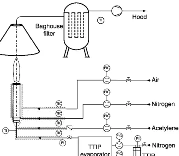
A schematic of the experimental setup is shown in Fig. 1. Powders are produced in a stainless steel coan-nular diffusion flame reactor, consisting of three concen-tric tubes. The inner diameter of the central tube is 4.8 mm, while the subsequent first and second annuli have inner–outer diameters of 5.6–6.4 mm and 7.3–9 mm, respectively. A mixture of TTIP/nitrogen (99.9995% Pangas, Zurich, Switzerland) and 0.2–0.65 l/min acety-lene (99.99% Pangas) is fed through the central tube. In the first annulus, 0.05 l/min nitrogen is provided to pre-vent particle deposition on the burner mouth,12
and 1.15 l/min air is fed through the second annulus. An evaporator system [Bronkhorst CEM 100W (evaporator), Bronkhorst EL-Flow201 (gas mass flow controller), and Bronkhorst Liqui-Flow L1 (liquid mass flow control-ler)]13 delivers titanium tetraisopropoxide (TTIP, Al-drich, >97%, distilled over vacuum prior to use) at 145 °C into the burner, using 1.13 Llmin nitrogen as carrier gas resulting in 5 g/h TiO2. The reactant composition in the
flame is characterized by the equivalence ratio (EQR), which is the fuel (acetylene and TTIP) to oxidant molar ratio to the stoichiometric fuel to oxidant ratio.14
The product powder (5–8 g/h, depending on the carbon content) is collected on glass fiber filters (Whatman GF/ A, 15 cm in diameter) using a vacuum pump (Vacuu-brand RE8, Germany). The Brunauer–Emmett–Teller
(BET)-equivalent specific surface area (SSA) of the product powder is determined from a 5 point nitrogen adsorption isotherm in the relative pressure range p/p0⳱ 0.05 to 0.25 (Tristar, Micromeritics Instruments
Corp.). The average primary particle diameter is calcu-lated by dBET⳱ 6 / ( × SSA), where is the particle
density. The rutile content and crystal size15
are obtained by XRD (Bruker D8 advance diffractometer, 40 kV, 40 mA, Bragg–Brentano geometry, 2 ⳱ 20° to 70°, step size 0.02°, at a scan speed of 0.24°/min) using the fun-damental parameter approach (Rietveld method).15 The carbon content is determined by thermogravimetric analysis (TGA) with a thermobalance (TGA/SDTA851e, LF/1100 °C, Mettler-Toledo AG) using a standard heat-ing sequence.5
The transmission electron microscope (TEM) pictures of the product powder were taken with a Zeiss electron microscope 912 Omega with ProScan and slow scan charge-coupled device (CCD) camera operated at 100 kV, while the high-resolution (HR) TEM images were ob-tained with a CM30ST microscope (Philips, LaB6 cath-ode, operated at 300 kV). Furthermore, TEM for the electron energy loss spectra (EELS) were performed with a Tecnai F30 FEG microscope (Philips, Schottky field emitter, operated at 300 kV). The TEM images were recorded close to Scherzer defocus or at an even higher defocus to increase the image contrast. An energy filter [Gatan imaging filter, (GIF)], which is installed below the Tecnai F30 FEG, allows recording EELS and element specific images (elemental maps) by means of the elec-tron spectroscopic imaging (ESI) technique. The so-called three-window method was applied for the mappings: An image is taken after a suitable ionization edge of the corresponding element (post-edge image, ⌬E3), two additional images (pre-edge 1,⌬E1, and
pre-edge 2,⌬E2) are recorded at energy losses smaller than
the ionization edge. Only the electrons passing through a selected energy slit (8–30 eV wide) contribute to these images. Specimen drift during recording of these images is compensated for by a cross-correlation algorithm implemented in the software of the GIF (Digital Micro-graph, Gatan). The pre-edge images are used for an ap-proximate determination of the unspecific background, which is then subtracted from the post-edge image lead-ing to an elemental map with enhanced contrast. The image series were recorded with a Slow Scan CCD cam-era (2048 × 2048 pixels), and ESI images were calculated with the software Digital Micrograph.
III. RESULTS
Figure 2 shows XRD patterns of the carbon-titania powders made at 0.2, 0.3, 0.46, and 0.65 l/min acety-lene flow rate resulting in 0.5, 15, 40, and 52 wt.% C, respectively. At the investigated process conditions FIG. 1. Experimental set-up for single-step, continuous production of
(0.5–52 wt.% C) no TiC was formed during simultaneous formation of carbon and TiO2. Increasing the carbon
content decreases the rutile content of the powders, con-sistent with the results of Inagaki and co-workers.10,11 The thermogravimetric analysis (TGA) curves (not shown) of the carbon-titania powders showed a slight decrease of 0.5–1 wt.% when heating up the powders from 120 to 800 °C under nitrogen atmosphere followed by a rapid weight loss (0.5–52 wt.%, depending on the C-content) when switching the atmosphere to oxygen at 800 °C. The former weight loss can be attributed to re-moval of chemisorbed water, surface OH-groups and any volatile organic compounds, while the latter is directly related to non-volatile carbon (soot) oxidation and re-moval as CO2 or CO.
5,16
The sample weight remains constant when further heating the powder to 1000 °C, since the TiO2surface is free of OH groups at this temperature.
16
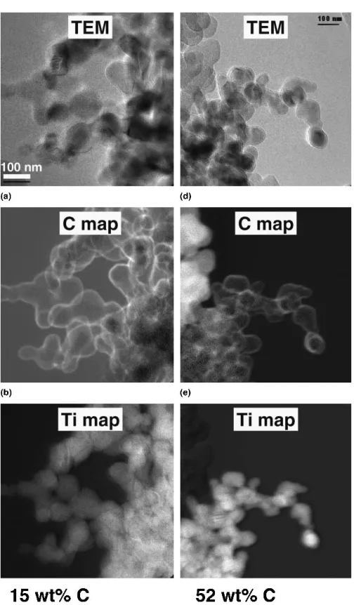
Figure 3 shows TEM pictures of the carbon-titania powders containing (a) 15 wt.% and (b) 52 wt.% carbon, respectively, as well as HRTEM of the corresponding powders (c) 15 wt.% and (d) 52 wt.%. The degree of agglomeration of these particles is similar to commer-cially available, similarly sized TiO2 (Degussa P25).
Coated TiO2 particles can be observed clearly in
Figs. 3(a) and 3(b). In the HRTEMs [Figs. 3(c) and 3(d)] the typical curved shape of the graphitic layer structure of carbon can be clearly distinguished from the linear TiO2
lattice structure. The thickness of this C coating layer is 2–3 nm, relatively homogeneous through all particles and
does not seem to depend on the carbon content from 15–52 wt.% carbon. At 52 wt.% carbon, some noncoated particles can be observed [lower right part in Fig. 3(b) and lower left part in Fig. 3(d)]. Elemental mappings of C and Ti are shown in Fig. 4 for the samples of Fig. 3. These pictures further corroborate that the carbon is rela-tively homogeneously distributed on the TiO2surface. In
addition, at higher carbon content (e.g., 52 wt.%) pure carbon particles are formed next to the carbon-coated TiO2 [Figs. 4(e) and 4(f)]. In the 15 wt.% carbon-TiO2
fewer pure carbon particles were detected (not shown). Furthermore, in all powders, sparsely, a few uncoated TiO2 particles were detected during extensive HRTEM
and elemental mapping analysis.
Figure 5 shows the specific surface area (SSA, circles, left axis) and the rutile content (triangles, right axis) of the carbon-titania powders as a function of the acetylene flow rate. Increasing the acetylene flow rate from 0.2 to 0.65 l/min increases the SSA from 29 to 62 m2/g. The SSA increases rapidly from 0.2 to 0.3 l/min of acety-lene and then slower reaching nearly an asymptotic value (∼60 m2
/g) at higher the acetylene flow rates (>0.5 l/min). The XRD rutile content decreases sharply from 68 to 40 wt.% by increasing the acetylene flow rate from 0.2 to 0.3 l/min, and then decreases to 17 wt.% when the acetylene flow rate is further increased to 0.65 l/min.
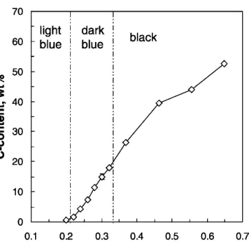
Figure 6 shows the carbon content of the powders of Fig. 5 as a function of the acetylene flow rate. Up to 0.2 l/min acetylene flow, hardly any carbon (0.5 wt.%) is detected in the product powder that appears light blue indicating titania suboxides. With increasing acetylene flow rate to 0.65 l/min the carbon content of the powder increases steadily up to 52 wt.%. The visual appearance of the powders changes from light blue (0.2 l/min C2H2)
to dark blue up to 0.32 l/min C2H2to black for more than
0.32 l/min C2H2(Fig. 6).
When the weighed particle diameter from nitrogen ad-sorption is calculated using anatase ⳱ 3.84 g/cm
3 , rutile⳱ 4.26 g/cm 3 , andcarbon⳱ 1.8 g/cm 3 for soot17 (or 2.27 g/cm3for graphite18) as well as the average XRD crystallite size15(Fig. 2) as functions of the powder car-bon content, two distinct regimes are observed (Fig. 7). If the carbon content increases from 0.5 to 15 wt.%, the dXRD(circles) and the dBETdecrease sharply (from 58 to
39 nm and from 52 to 37 nm, respectively). The dXRD
decreases less pronounced from 39 to 24 nm, when fur-ther increasing the carbon content from 15 to 52 wt.%, while the dBET stays almost constant at about 38 nm
(using the soot density, squares) or at 34 nm (using the graphite density, triangles). These primary particle sizes (dBET and dXRD) agree well with the corresponding
sizes observed by TEM (Fig. 3) indicating single crystals. The carbon-yield [carbon detected in the prod-uct powder divided by the carbon (acetylene and TTIP) FIG. 2. X-ray diffraction pattern of flame-made carbon-coated TiO2
with 0.5, 15, 40, and 52 wt.% C prepared in this work. A and R indicate the anatase and rutile peaks, respectively.
fed to the system] is in the order of 5% for the high-est acetylene flow rates (>0.37 l/min), which is in agree-ment to that observed for carbon-coating of fumed silica.3The rest of the carbon was used in the combustion process.
IV. DISCUSSION
Increasing the acetylene flow rate from 0.2 to 0.65 l/min increases the excess of fuel in the flame sig-nificantly (EQR increases from 4.2 to 8.8). Since the combustion temperature is lowered by increasing the EQR,19the SSA increases as observed in Fig. 5. This is in agreement with flame aerosol synthesis of carbon-silica powder.3At these fuel-rich conditions, lower EQRs (EQR⳱ 4.2 at 0.2 l/min C2H2) result in higher
tempera-tures that increase carbon oxidation (Fig. 6) and the sin-tering rate of titania particles. This is consistent with the high rutile content of powders at high temperatures20 made at low acetylene flow rates (Fig. 5).
After the TiO2 is coated with carbon, adding more
carbon (up to 15 wt.% carbon) first leads to a less sparse and thicker layer as observed by TEM while the TiO2 particle size decreases with increasing acetylene
flow rate (Fig. 7). At even higher carbon contents (>10 wt.%), the dXRD decreases rather slowly with
in-creasing carbon content (Fig. 7), since carbon appears to hinder TiO2sintering and through the reduced flame
tem-perature that decreases the sintering rate.11 The particle diameter calculated from nitrogen adsorption data (spe-cific surface area), however, stays constant. HRTEM pictures show a carbon layer of 2–3 nm covering the TiO2particles (Figs. 3 and 4). Calculating the amount
of carbon that is needed to cover primary particles of dXRD ⳱ 39 nm [Figs. 3(a), 3(c), and 4(a)–4(c)] with
a 2.3-nm-thick C layer (using C ⳱ 1.8 17
) or 1.9-nm-thick C layer (using C ⳱ 2.27
18
) results in powders containing 15 wt.% carbon. This is in good agreement with thickness of the C layer observed from TEM for the 15 wt.% C and consistent with the EELS measurements, FIG. 3. Transmission electron micrographs of flame-made carbon-coated titania with (a) 15 wt.% and (b) 52 wt.% carbon and HRTEMs of the same powders (c) 15 wt.% and (d) 52 wt.%. The particles in the lower right part of (b) and lower left part of (d) are not coated and do not contain crystal reflections that are typical for crystalline TiO2suggesting that these are carbon particles coexisting with carbon-coated titania particles that
where carbon coated TiO2and almost no separate carbon
particles were detected. Thus, the produced carbon is bound almost completely to the TiO2 surface at these
process conditions.
From TEM (Fig. 3) it becomes apparent that the 2–3-nm carbon layer does not increase in thickness with increasing the carbon content of the powder from 15 wt.% [Fig. 3(c)] to 52 wt.% [Fig. 3(d)] as one might have FIG. 4. (a,d) Transmission electron micrographs along with the corresponding (b,e) elemental C and (c,f) Ti maps for carbon-TiO2powders
expected from the evolution of the specific surface area (Fig. 5). Here, pure carbon particles are formed next to carbon-coated titania as can be observed in the lower right part of Fig. 3(b) and the lower left part of Fig. 3(d), for example. These particles are not coated and do not contain the crystal reflections typical for TiO2.
There-fore, these particles should be pure carbon particles that
coexist with the carbon-coated titania as was confirmed by elemental mapping of C and Ti (Fig. 4). These pure carbon particles grow even to larger sizes when increas-ing the acetylene flow rate or the overall carbon content of the powder that decreases the specific surface area (Fig. 5). However, the average primary particle diameter remains almost constant with increasing acetylene flow rate (0.3–0.65 l/min) as the overall density of the mixed carbon-titania powder decreases (Fig. 7). The amount of carbon that is needed for covering 27-nm-diameter TiO2 particles (which corresponds to dXRD of the TiO2
powder containing 52 wt.% C) completely with a 2- or 3-nm carbon-layer, is 19 or 28 wt.% C (using using C⳱ 1.8
17
) and 23 or 32 wt.% C (using C⳱ 2.27 18
). Since in the present case 52 wt.% C powders were pro-duced, this indicates that about half of the carbon is used for the TiO2 coating while the rest forms individual
(pure) carbon particles consistent with TEM [Figs. 3(b), 3(d), and 4(d)–4(f)].
These flame-made carbon-coated TiO2powders differ
from those made by Koc and co-workers6that contained porous carbon layers covering the TiO2 particles, since
adsorption/desorption isotherms of the present flame-made powders revealed them to be non-porous. These isotherms exhibited only a slight hysteresis at high rela-tive pressures, which was even less pronounced than that shown by Stark et al.21 for flame-made vanadia-doped titania. This hysteresis is attributed to the sintering necks FIG. 5. Specific surface area (circles) and rutile content (triangles) of
carbon-titania nanostructured powders as a function of acetylene flow rate fed to the diffusion flame aerosol reactor.
FIG. 6. Carbon content and regions of visual powder appearance of carbon-titania nanostructured powders as a function of the acetylene flow rate fed to the diffusion flame aerosol reactor.
FIG. 7. Average crystal size (circles) of titania (obtained by XRD) and average primary particle size (obtained by nitrogen adsorption, BET) of the nanostructured carbon-titania powders as a function of their carbon content. Here, two densities for carbon [soot17(squares) and graphite18(triangles)] were used to calculate the average BET particle diameter.
between the agglomerated primary particles. The present process has the advantage that the used precursors for TiO2 and carbon (TTIP and acetylene) do not contain
halide compounds as that in the process of Inagaki et al.10
Furthermore, the formation of sub-stoichiometric titania might be advantageous during further processing of this powder to TiC, since Swift and Koc8
showed that the formation of TiC from carbon-coated TiO2proceeds
through the formation of lower oxides of titania (TiO2–x).
The flame-made particles are of high purity (TGA re-sults),5,16and they are typically of a narrow size distri-bution with geometric standard distridistri-butions between 1.4 and 1.8.22If for certain applications even the present low degree of agglomeration of the TiO2 (single particles,
doublets and triplets) is too high, the process conditions can easily be adjusted to produce non-agglomerated TiO2
as demonstrated recently.22
V. CONCLUSIONS
The feasibility of a continuous, one-step process for synthesis of carbon-coated titania particles with closely controlled characteristics was presented. Homogeneously coated particles were produced in a diffusion flame aero-sol reactor with carbon contents from 0.5 to 52 wt.% and a graphitic carbon layer thickness of up to 3 nm at pro-duction rates up to 8 g/h. For powders containing up to 15 wt.% carbon, nearly all carbon is bound to the TiO2
particles, while increasing the carbon content of the pow-der by increasing the acetylene flow rate resulted in the formation of separate carbon particles next to the carbon-coated titania particles but did not increase the thickness of the carbon layer of the latter ones. For TiO2powders
made with the highest carbon content (52 wt.% C) roughly half of the carbon is used for coating, while the rest forms individual (pure) carbon particles in agree-ment with TEM. The specific surface area and crystal-linity of the carbon titania powder was closely controlled by the acetylene flow rate. Doubling the acetylene flow rate increased the specific surface area from 29 to 62 m2
/g, while at the same time the rutile content of the powders decreased drastically from 68 to 17 wt.%. Fur-thermore, the color of the product powder changed from
light blue for TiO2suboxides made at low acetylene flow
rates to dark blue and eventually black powders that were made at the highest carbon contents.
ACKNOWLEDGMENTS
We acknowledge the financial support of the Swiss Commission for Technology and Innovation, KTI Top-Nano21 (287-044-01), Dr. Frank Krumeich (ETHZ) for the HRTEM and elemental mapping experiments, and Dr. Martin Müller (ETHZ) for the TEM.
REFERENCES
1. Y. Hareyama, Patent EP 985,638 A1 (1999).
2. S.E. Pratsinis, Prog. Energy Combust. Sci. 24, 197 (1998). 3. P.T. Spicer, C. Artelt, S. Sanders, and S.E. Pratsinis, J. Aerosol
Sci. 29, 647 (1998).
4. H.K. Kammler and S.E. Pratsinis, J. Nanoparticle Res. 1, 467 (1999).
5. H.K. Kammler, R. Mueller, O. Senn, and S.E. Pratsinis, AIChE J.
47,1533 (2001).
6. R. Koc and G.C. Glatzmaier, U.S. Patent No. 5 417 952 (1995). 7. R. Koc, J. Eur. Ceram. Soc. 17, 1309 (1997).
8. G.A. Swift and R. Koc, J. Mater. Sci. 34, 3083 (1999). 9. R. Koc, C. Meng, and G.A. Swift, J. Mater. Sci. 35, 3131 (2000). 10. M. Inagaki, H. Miura, and H. Konno, J. Eur. Ceram. Soc. 18, 1011
(1998).
11. T. Tsumura, N. Kojitani, I. Izumi, N. Iwashita, M. Toyoda, and M. Inagaki, J. Mater. Chem. 12, 1391 (2002).
12. H.K. Kammler and S.E. Pratsinis, Chem. Eng. Process. 39, 219 (2000).
13. W.J. Stark, S.E. Pratsinis, and A. Baiker, J. Catal. 203, 516 (2001). 14. S.R. Turns, An Introduction to Combustion; Concepts and
Appli-cations, 2nd ed. (McGraw-Hill, New York, 1996).
15. R.W. Cheary and A. Coelho, J. Appl. Crystallogr. 25, 109 (1992). 16. R. Mueller, H.K. Kammler, K. Wegner, and S.E. Pratsinis,
Lang-muir 19, 160 (2003).
17. D.F. Kronholm and J.B. Howard, Twenty-eighth Symposium (In-ternational) on Combustion (The Combustion Institute, Pitts-burgh, PA, 2000), p. 2555.
18. P.W. Atkins, Physikalische Chemie, 2nd ed. (VCH-Verlag, Wein-heim, Germany, 1990).
19. I. Glassman, Combustion, 3rd ed. (Academic Press, San Diego, CA, 1996).
20. K.J.D. MacKenzie, Trans. J. Brit. Ceram. Soc. 74, 121 (1975). 21. W.J. Stark, K. Wegner, S.E. Pratsinis, and A. Baiker, J. Catal. 197,
182 (2001).
22. H.K. Kammler, R. Jossen, P.W. Morrison, Jr., S.E. Pratsinis, and G. Beaucage, Powder Technol. (2003, in press).