Adaptive Channels for Wireless Networks
by
Andrew G. Chiu
Submitted to the Department of Electrical Engineering and Computer
Science
in partial fulfillment of the requirements for the degrees of
Master of Engineering
and
Bachelor of Science in Electrical Engineering and Computer Science
e
at the MAssAcHU
Massachusetts Institute of Technology
,JUL1
May 1999
rev
\LIBRARIES
©
Andrew G.
Chiu,
VCMXCIX.
All
rights reserve.
The author hereby grants to MIT permission to reproduce and
distribute publicly paper and electronic copies of this thesis document
in whole or in part, and to grant others the right to do so.
A u th or ...
...
Department of Electrical Engineering and Computer Science
May 21, 1999C ertified by ...
...
...
..
.
...
John V. Guttag
Professor
omputer Science and Engineering
-. ,, ,53 esis-ilgipervisorAccepted by...
Arthur C. Smith
Chairman, Department Committee on Graduate Theses
Adaptive Channels for Wireless Networks
by
Andrew G. Chiu
Submitted to the Department of Electrical Engineering and Computer Science on May 21, 1999, in partial fulfillment of the
requirements for the degrees of Master of Engineering
and
Bachelor of Science in Electrical Engineering and Computer Science
Abstract
This thesis presents the design, implementation, and analysis of an adaptive wireless network that is capable of dynamically modifying the physical layer of its wireless links. Nodes in such a network are able to change many aspects of the physical layer, including coding, modulation, and multiple access. With this technology, a wireless network can dynamically adapt its physical layer to changing environmental conditions, traffic patterns, and application requirements, resulting in better spectrum utilization, power consumption, and application level performance.
The approach presented in this thesis overcomes many of the limitations imposed
by today's wireless networks. Software radio technology is exploited to provide the
necessary flexibility in the physical layer. Since changes to the physical layer must be performed quickly and reliably in a lossy wireless environment, a modification mech-anism, including a reliable protocol, was designed and implemented. Putting these two technologies together, the end result is the implementation of an adaptive wire-less network infrastructure that is capable of modifying its physical layer to increase performance. While the issue of the decision rules that are used to determine what changes are necessary is beyond the scope of this thesis, the presented infrastructure is general enough to support any method of determination.
Thesis Supervisor: John V. Guttag
Acknowledgments
I would like to show my gratitude to the following people for their invaluable
contri-butions, without whom I could not have reached this point in my life:
" Vanu Bose, for taking a chance on an unproven freshman and being an awesome
supervisor throughout my time at the lab. I am extremely grateful for his guidance, assistance, and insight into SpectrumWare, technology, sports, and life in general.
" John Guttag, for finding the time in his busy schedule to provide his guidance,
advice, and support.
* Cindy Liang, for providing the love, encouragement, and understanding that helped me through.
" Michelle Girvan, for your friendship, advice, and all of the intellectual and
mathematically-inclined discussions during our years at MIT.
" And finally, my family, for all of your love and support over the years and for
Contents
1 Introduction 11
1.1 Why Adaptive Physical Layers. . . . . 11
1.2 Creating Adaptive Physical Layers . . . . 13
1.2.1 The Flexibility of Software Radio Technology . . . . 14
1.2.2 Coordination of Physical Layer Modifications . . . . 14
1.3 Impact of Adaptive Physical Layers on Wireless Networks . . . . 15
1.4 T hesis Scope . . . . 16
1.5 Contributions . . . . 16
1.6 R oad M ap . . . . 17
2 SpectrumWare Virtual Radio Architecture 19 2.1 System Architecture . . . . 20
2.1.1 I/O System . . . . 21
2.1.2 The SPECtRA Programming Environment . . . . 22
2.2 Software Radio Layering Model . . . . 23
2.3 Application to Adaptive Networks . . . . 24
3 Protocol for Physical Layer Modification 27 3.1 Communication Model . . . . 27
3.2 Basic Protocol . . . . 29
3.2.1 Downstream Modification . . . . 29
3.2.2 Upstream Modification . . . . 32
3.4 Simultaneous Request Resolution . . 3.4.1 Simplified Analysis . . . . 3.4.2 Simulation . . . .
3.5 Summary . . . .
4 System Design and Implementation
4.1 Virtual Network Device Application . . . . 4.1.1 Virtual Physical Layer . . . . 4.1.2 Control Band . . . . 4.2 Executing Physical Layer Modifications . . . . . 4.2.1 Controlling the Adaptive Physical Layer 4.2.2 Modular Program Structure . . . . 4.2.3 Dynamic Code Loading . . . .
5 System Performance
5.1 Software Physical Layer Performance
5.1.1 Latency Components . . . . .
5.1.2 Results . . . .
5.1.3 System Bottlenecks . . . .
5.2 Modification Protocol Performance
5.2.1 Performance Criteria . . . . .
5.2.2 Results . . . .
6 Conclusions and Future Work
6.1 Observations and Discussion of Trends . . . .
6.2 Future W ork . . . .
6.2.1 Effective Channel Monitoring . . . . .
6.2.2 Quantification of Performance Metrics
6.2.3 Traffic-driven Modification Policy . . .
6.2.4 RadioActive Networks . . . . 6.3 Conclusion . . . . . . . . 34 . . . . 36 . . . . 38 . . . . 41 43 44 45 47 48 48 50 51 53 . . . . 5 3 . . . . 5 4 . . . . 5 6 . . . . 5 9 . . . . 6 0 . . . . 6 0 . . . . 6 1 65 . . . . 66 . . . . 67 . . . . 67 . . . . 68 . . . . 69 . . . . 70 . . . . 70
List of Figures
2-1 The SpectrumWare architecture . . . . 21
2-2 The SPECtRA environment. . . . . 22
2-3 The Software Radio Layering Model shifts many physical layer
func-tions into software. The shaded layers comprise the traditional physical layer. . . . . 26
3-1 Model of the communication setup. . . . . 28
3-2 Basic protocol to modify a downstream link. Message format: link(message) 29
3-3 Protocol to modify a downstream link, with lost messages and retrans-m ission . . . . . 31
3-4 Basic protocol to modify an upstream link. . . . . 32 3-5 Expected number of rounds until success as a function of message loss
probability. . . . . 33
3-6 Success probability after two attempts of the protocol as a function of message loss probability. . . . . 35
3-7 Expected time to resolve a collision as a function of the range of random wait times. All times in units of D. . . . . 39 3-8 Average time to resolve a collision as a function of the range of random
wait times with different message loss probabilities. All times in units
of D . . . . 40
4-1 Comparison of the (a) traditional approach with the (b) SpectrumWare
4-2 The Virtual Physical Layer performs the processing that is tradition-ally performed on the network interface card . . . . 46 4-3 The structure of an example Virtual Network Device. . . . . 47 4-4 The interface of the network management application . . . . 49
5-1 Path through the components of a wireless communication link for
both (a) a SPECtRA-based network and (b) an ethernet network. . . 55
5-2 Plot of the break-even time, TB, as a function of the percent increase in bandwidth, BcurrentBnew - 1. . . . .
63
List of Tables
5.1 CPU overhead of the software physical layer running on a Pentium II
450 and using one bit per symbol. . . . . 54
5.2 Average delay per 84 byte ping packet through the components of the w ireless link. . . . . 57 5.3 Average processing time per 84 byte ping packet for each component
of the transmit software. . . . . 58
5.4 Average processing time per 84 byte ping packet for each component of the receive software. . . . . 59 5.5 Average latency incurred and break even times (TB) for various
Chapter 1
Introduction
The goal of wireless networking is to provide the same high performance of a wired network while allowing the added benefit of mobility. Today's wireless networks do not achieve this goal. Users of wireless networks experience intermittent connectivity, low bandwidth, occasional dropped connections, restricted mobility, and poorer overall performance.
One cause of these performance limitations in existing wireless networks is the static functionality at the physical layer. A wireless network today is constructed with one, predetermined physical layer. This inflexibility leads to inefficient use of resources, such as bandwidth and power, and sub-optimal performance.
1.1
Why Adaptive Physical Layers
By using adaptive physical layers, flexibility can be introduced into the physical layer
to improve performance. The physical layer can then be modified for changing needs and requirements. Thus, adaptive physical layers provide the functionality to allow better use of the spectrum, allow mobility between different wireless networks, and increase overall performance.
Since the wireless links in today's networks are designed for the worst case and static, a network is unable to take advantage of better-than-worst case conditions. Link performance is thus upper bounded by the characteristics of the physical layer
and not by current environmental conditions. For example, suppose that the noise level in the environment decreases, increasing the signal-to-noise ratio. This event increases the potential maximum throughput of a given channel. However, the net-work is unable to change its channel coding or filtering to increase throughput since it cannot modify its physical layer. Static networks are also susceptible to interfer-ence localized to certain critical frequencies. For example, the operation of a wireless network using the 2.4 GHz ISM band can be disrupted by a microwave oven, which operates at about 2.45 GHz [61. Such a network could potentially increase perfor-mance by modifying its physical layer to avoid this localized interference by using the portions of the ISM band above and below the interference instead of the entire band.
There is no direct connection between communication link performance and ap-plication requirements in today's wireless networks. The design of the physical link provides a set of operational parameters, such as latency and bit error rate, that cannot be changed. Different applications, however, have different requirements. For example, an application transferring data can tolerate some latency, but it wants a bit error rate as close to zero as possible. On the other hand, a real-time video application, such as videoconferencing, can tolerate occasional bit errors, which re-sults in occasional pixel errors or dropped video frames, but requires low latency. These applications want Quality of Service (QoS) at the physical layer that cannot be provided by today's systems. One solution is to subdivide the available band for each type of data. A slice of the spectrum is dedicated to video, where bandwidth is guaranteed to the application, and the rest of the band is shared among all of the users transferring data. Each subdivision has a different physical layer that meets the service requirements of the application it serves.
There are many possible applications of wireless networking technology that have not been realized because of the inconsistent performance of current networks. Be-cause of the limitations imposed by the static nature of current implementations, the proliferation of wireless networking and its promise of anytime connectivity has been hindered. For example, a possible architecture for wireless networking is for a mobile
node to be connected to several different overlay networks, each of which applies to a different coverage area [15, 16]. The smallest coverage area is a building-area network, and the others, in order of increasing size, are a campus-area, metropolitan-area, and a regional-area network. Each network is characterized by different parameters such as bandwidth, latency, and bit-error rates [15, 16]. Without the ability for a wireless node to dynamically switch between multiple physical layers, such an architecture must be constructed with the same physical layer at all levels of the overlay network system, or a node is forced to carry several different wireless network adapters. Even though this restriction does not prevent the use of overlay networks, it greatly hinders its introduction into commercial use.
1.2
Creating Adaptive Physical Layers
The key enhancement of an adaptive wireless network is a flexible physical layer. This allows the network to optimize at the physical layer in addition to the network and link layers. Information may be passed between the different communication layers (physical, link, network, and application), allowing cross-layer optimization. For example, information about bit error rates, determined at the physical layer, may be used to adjust packet sizes, which is a network layer parameter. Conversely, packet loss tolerances for applications may be used to adjust bandwidth usage and channel coding, which are both physical layer parameters. With the flow of information between the layers, optimizations improve overall system performance rather than individual layer performance.
There are three issues that must be addressed to effectively utilize adaptive phys-ical layers. The first is the decision on when a modification is necessary and what change is to be implemented. Functionality needs to be built into the network to detect changes in the environment or user requirements and to determine which mod-ifications to the wireless channels are necessary to improve performance. This issue, while not the focus of this thesis, is addressed as future work in chapter 6. The second issue is the execution of these modifications, and the third issue is the coordination
between the two ends of the wireless link to ensure quick and reliable modifications to the physical layer. These two issues are covered in this thesis, and software radio technology provides the flexibility that is required to address them.
1.2.1
The Flexibility of Software Radio Technology
Software radio technology has the promise to provide two levels of flexibility: static and dynamic. Static flexibility is the ability to modify the physical layer at setup time. However, once the radio is running, control over the physical layer is limited. Dynamic flexibility is the ability to modify the physical layer at runtime while communication is occurring. In this case, modifications to the physical layer occur automatically and transparently to the user with minimal interruption in service.
The ability for software radios to perform static modifications has already been demonstrated. The Speakeasy Multiband Multimode Radio uses programmable pro-cessing to emulate more than 15 existing military radios, operating in frequency bands between 2 and 200 MHz
[13].
In addition, many applications in the SpectrumWare project at MIT deal with setup-time modifications. The same device, using the same hardware, can be set up to be an analog TV receiver, an AMPS cellular receiver, or a wireless network interface just by changing the code [3].Software radio technology also provides a mechanism for overcoming the limita-tions of current wireless networks by permitting dynamic modification of the physical layer [3]. Software control over the physical layer has been demonstrated, and the extension to dynamic "on-the-fly" adaptation is the next step. To support this rapid, run-time adaptation, a mechanism is needed to ensure quick, coordinated modifica-tions at both ends of the wireless link.
1.2.2
Coordination of Physical Layer Modifications
The software radio-based adaptive wireless node uses the current physical layer to transmit the changes required to construct the new physical layer. Thus, it is impor-tant that the nodes on both ends of the wireless link agree to change to a new link
and set up that new link before the current link is destroyed.
Since the underlying communication channel is a wireless connection, it is inher-ently lossy and unreliable. Bit errors are common, and message losses are expected. Thus, a protocol is needed to handle message losses and ensure that the modification occurs rapidly even in a poor environment.
The adaptive channels described in this thesis are designed to be extremely gen-eral. The design of the particular wireless network that utilizes these adaptive chan-nels is not fixed, and the method by which individual wireless links are modified is also not fixed. It is possible that a particular network configuration allows multiple modification requests to be issued within the network at any one time. In such a case, there must be a mechanism to handle the situation where a wireless node issues a modification request and simultaneously receives a conflicting request.
1.3
Impact of Adaptive Physical Layers on
Wire-less Networks
A wireless network using software radios can exert control over the physical layers of
its communication links. By executing a reliable modification protocol when modify-ing its wireless links, a network can quickly change the communication channel with minimal interruption in service. In many cases, the latency incurred by the modi-fication will be small enough to be unnoticeable by the user. An adaptive network that utilizes both software radios and a reliable modification protocol can achieve the following goals:
" The physical layer can be adapted to meet changing environmental conditions,
improving link performance.
* The physical layer can be adapted to meet the different requirements of each application, improving the overall application performance.
" Optimizations can be made across OSI layers, resulting in better overall system
* System resources, such as power and CPU utilization, can be better managed, leading to more efficient operation.
Adaptive wireless networks provide the solution to many of the problems that limit existing systems. The ability of a wireless network to adjust its operational parameters to maintain or improve the performance of the system under changing circumstances brings the idea of reliable, anytime connectivity closer to reality.
1.4
Thesis Scope
In order to build an adaptive wireless network, many new technologies need to be developed. By designing the underlying infrastructure, this thesis is the first step. To demonstrate this infrastructure, this thesis develops a protocol for the coordination of physical layer modifications and presents an implementation of a two node adaptive network.
In the implemented network, each node is equipped with a software radio-based wireless network interface device and programmed with the coordination protocol. These nodes are able to reliably perform modifications to the physical layer of the network, such as a change in the modulation. In order to assess the tradeoffs of this approach, the performance of this network is measured in terms of both the co-ordination protocol and the software-based network interface. By building a basic adaptive network and characterizing its performance, this thesis provides insight into the strengths and weaknesses of this software approach to adaptive wireless network-ing.
1.5
Contributions
The major contributions of this thesis are:
* The demonstration that software radio technology can provide dynamic flexi-bility in the physical layer of wireless network links.
" The design, analysis, and implementation of a reliable protocol for dynamically
modifying network links.
" The implementation of an infrastructure upon which future research into
adap-tive wireless networks can be based.
1.6
Road Map
The next two chapters deal with the major building blocks for an adaptive wireless network. Chapter 2 describes software radios and the SpectrumWare architecture, which serves as the platform upon which our network is built. This chapter also introduces the software radio layering model, which allows any physical layer to be concisely specified. Chapter 3 introduces and analyzes a protocol that provides a reliable method for modifying the physical layer quickly and transparently to the user.
After describing the individual components of the system, chapter 4 describes the design of the network infrastructure and its implementation in the SpectrumWare architecture. Chapter 5 evaluates both the performance of individual components of the system and the overall performance of the network. Finally, chapter 6 concludes with observations and suggestions for future work.
Chapter 2
SpectrumWare Virtual Radio
Architecture
A software radio is a radio device whose modulation waveforms are defined and
gen-erated in software, which introduces flexibility by allowing software programmability
[11]. Most software radio architectures utilize application-specific digital hardware
or digital signal processors under software control [5, 13]. Taking the implementa-tion one step further, a virtual radio is a communicaimplementa-tions device that performs all of its digital signal processing on a commercial, off-the-shelf workstation or personal computer [3].
The SpectrumWare virtual radio system described in this chapter is ideal for developing an adaptive wireless network. Many of the properties of the SpectrumWare system are exploited in the design of the adaptive network presented in this thesis. The following section gives an overview of the SpectrumWare system and highlights the aspects of the system that are central to the design of the adaptive network. Section 2.2 describes the software radio layering model which provides a specification for any physical layer, and section 2.3 describes the importance of these technologies on adaptive wireless networks.
2.1
System Architecture
The SpectrumWare virtual radio project at the MIT Laboratory for Computer Sci-ence demonstrates the feasibility of using general purpose processors coupled with wideband digitization to implement a software radio [3]. By using a general purpose processor and a standard operating system (Linux), all of the signal processing rou-tines can be implemented in a high-level programming language, such as C++. This type of architecture provides an excellent design and development platform to explore the many advantages of software-defined radios, including [2]:
" greater flexibility in the range of functionality that can be implemented,
" ease of portability of software between processors allowing the software radio
platform to track the performance of Moore's Law, and
" tighter coupling between the application and the radio allowing for better system
optimization.
The SpectrumWare architecture is an excellent platform upon which to develop and implement an adaptive wireless network. Since all of the physical layer functions are performed by software in user space, modifications to the physical layer are easily executed by changing user-level code. Also, using a general purpose platform running Linux allows integration of the wireless network with the user application and the operating system. The software-based physical layer can directly interface with the bottom of the network stack through a device driver, and it can receive and send network traffic through sockets. The first ability is central to the operation of the wireless network interface, and the second ability allows this network interface to dynamically modify its physical layer.
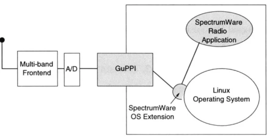
The SpectrumWare virtual radio architecture, shown in figure 2-1, consists of two main components: the I/O system and the application programming environment. The following two sections describe each of these components.
Figure 2-1: The SpectrumWare architecture.
2.1.1 I/O System
The I/O system is responsible for acquiring the frequency band of interest, digitizing it, and transporting the desired samples into host memory. The SpectrumWare sys-tem uses a multi-band frontend to convert the desired RF band to an IF frequency, samples the wideband IF waveform, and transports the resulting samples into host memory. Similarly, to transmit, the system transfers samples from memory to a D/A converter and then translates this IF waveform to the desired RF band.
The movement of samples between the A/D (and D/A) and host memory is per-formed by the General Purpose PCI I/O, or GuPPI [3]. It utilizes the PCI bus to perform continuous DMA between the GuPPI and host memory. However, these samples are placed in memory that is only accessible by the GuPPI device driver. To allow the radio application access to these samples, extensions were made to the operating system. Specifically, the virtual memory system was extended to provide a low-overhead, high-bandwidth transfer of data between the application and the de-vice driver. This extension allows for copy-free read and write calls to the GuPPI, which results in a high sample throughput between the application and the GuPPI. Using a 200 Mhz Pentium Pro running Linux with a 33 Mhz, 32 bit wide PCI bus, the maximum continuous data transfer rate is 512 Mbits/sec [3].
2.1.2
The SPECtRA Programming Environment
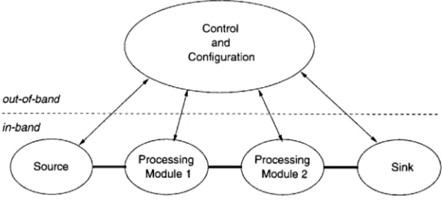
SPECtRA, or Signal Processing Environment for Continuous Real-time Applications, provides a platform for the implementation of real-time software radio applications [2]. The system, shown in figure 2-2, consists of two partitions: the in-band data processing module chain, and the out-of-band control section.
Control and Configuration
out-of-band
in-band
Source SourceModule 1 Processing Processing Sn
Module 2 Sn
Figure 2-2: The SPECtRA environment.
In SPECtRA, all of the signal processing occurs in modules. Each module, imple-mented as a C++ class, performs a specific task, such as FM modulation or channel filtering. By connecting a series of modules, specific applications can be built. For example, to create a single channel FM receiver application, a possible processing chain is:
o GuPPI Source - provides a wideband sample stream from the GuPPI o Channel Filter - selects the proper channel from the wideband IF signal o FM Demodulator - extracts the signal/voice from the FM carrier
o Filter - isolates the frequencies present in the desired audio signal o Audio Sink - provides an interface to the Linux audio driver
Modules are not associated with any particular application. By structuring the programming environment to be modular, code reuse is possible. Also, this modular-ity allows for incremental additions or changes to the processing chain to be executed
easily. To modify the above FM receiver into a single channel AM receiver, the only change that is required is to replace the FM Demodulator with an AM Demodulator. The remaining modules stay the same and no other code changes are necessary.
The out-of-band control portion of SPECtRA is responsible for everything outside the actual data processing. This includes creating and modifying the in-band process-ing chain, executprocess-ing communication between modules, and handlprocess-ing user interaction [2].
2.2
Software Radio Layering Model
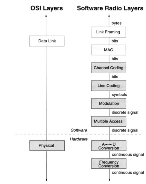
In order to allow modifications to a wireless communication system, there must be a mechanism to specify the signal processing requirements of the new system to the radio at each end of the connection. To address this issue, the SpectrumWare virtual radio architecture uses a model consisting of several well-defined processing layers that can be used to completely specify a wireless communications system [2]. This layering, shown in figure 2-3, is a refinement of the OSI layering model [17].
Each sublayer performs a distinct function, with the bottom four software sub-layers comprising the functions that are traditionally performed at the physical layer [2]:
" Link Framing: The traditional link layer is preserved. This is used to
trans-form the raw transmission facility into a line that appears free of errors to the network layer [17].
" Media Access Control (MAC): The primary MAC functions are mediating
shared medium access and collision avoidance.
" Channel Coding: Channel codes are used to reduce errors at the bit level
through error detection, error correction, or error prevention [14].
" Line Coding: Line codes control the statistics of the data symbols, such as
The desired parameters are determined by physical characteristics of the trans-mission medium.
" Modulation: This sublayer deals with the transformation between symbols
and signals.
" Multiple Access: The multiple-access sublayer implements techniques such
as TDMA and FDMA. Although the MAC layer may also involve a multiple access technique, this provides a very different function. Consider the IEEE
802.11 wireless networking standard [10]. The MAC layer provides multiple
access among users of a particular network, while the multiple access layer allows for the sharing of the spectrum between different networks.
This layering model provides a framework for specifying and building software radio applications. The layering provides a modular architecture in which a new communication system can be created by simply combining existing functional mod-ules instead of writing a new piece of software that encompasses all of the required physical layer functions. Incremental changes can be specified by swapping in the de-sired modules and removing the modules that have been replaced. This is important, since it reduces the overhead associated with loading the new physical layer code and implementing the desired changes.
A given system may only contain a subset of the layers. However, such a system
can be represented with all of the layers present, except that some of them do not manipulate the data in any way.
2.3
Application to Adaptive Networks
The SpectrumWare architecture provides an ideal platform for an adaptive wireless network. SpectrumWare, along with the software radio layering model, provides:
* Efficient, high-bandwidth I/O. The I/O system provides a 512 Mbits/sec transfer rate, which allows the system to process a frequency band as large
as 32 MHz'. This bandwidth is more than sufficient for networking purposes. For example, the IEEE 802.11 standard allocates 5 MHz channels in North America and Europe and 26 MHz channels in Japan, which are both within the limitations of this I/O system [10].
" Modular program architecture. Functions such as filters, modulation
for-mats, and coding techniques are written once, creating a library of reusable processing modules. Applications are then constructed from a common set of building blocks.
* Physical layer specification and representation. Any instance of a layer
of the software radio layering model maps to one or more processing modules. Thus, any particular physical layer specified by the software radio layering model translates into a chain of processing modules, each of which is taken from the common library of reusable modules.
" Method for adaptation. The out-of-band control code provides a mechanism
to modify the current radio application. Modifications are executed by taking the new physical layer representation and replacing the necessary processing modules. The control code can be extended to execute modifications in response to desired inputs, such as network messages or increasing error rates.
These properties allow the development of a software-based adaptive wireless net-work. SpectrumWare is well-suited for this application, and it provides a solid pro-cessing environment upon which the modification protocol and other intelligent code for determining physical layer changes can run.
Software Radio Layers
Software Hardware
continuous signal
Figure 2-3: The Software Radio Layering Model shifts many physical layer functions into software. The shaded layers comprise the traditional physical layer.
Chapter 3
Protocol for Physical Layer
Modification
For a wireless network to execute a modification to the physical layer of a particular link, the specification for the new physical layer must be known to both ends of the link. Messages must be exchanged so that both ends create and quickly switch over to the same new physical layer. Also, since the wireless environment is noisy and unpredictable, an adaptive wireless network requires a reliable protocol for exchanging the necessary messages. This chapter describes one such protocol and evaluates its reliability and latency characteristics.
3.1
Communication Model
A wireless link between two hosts A and B, as shown by the example in figure 3-1, is
described by two sets of parameters, one for downstream data traveling from A to B
(Pd), and one for upstream data from B to A (P,) . Each set of parameters contains one entry for each of five layers (MAC, channel coding, line coding, modulation, and multiple access) of the software radio layering model described in section 2.2. These parameters completely specify the physical layer. The two sets of parameters may be different or the same. For the case that they are the same, that one physical link may be viewed as two logical links, one for each direction. Each host transmits on
Tx parameters (Pd) MAC: none Channel Coding:
Reed-Solomon Line Coding: none Modulation: BPSK Multiple Access: FDMA AI Rx parameters (P) MAC: CSMA/CA Channel Coding: PLCP Line Coding: none Modulation: Gaussian FSK Multiple Access: Frequency Hopping u Rx parameters (Pd) MAC: none Channel Coding: Reed-Solomon Line Coding: none Modulation: BPSK Multiple Access: FDMA B Tx parameters (Pu) MAC: CSMA/CA Channel Coding: PLCP Line Coding: none Modulation:
Gaussian FSK Multiple Access:
Frequency Hopping
Figure 3-1: Model of the communication setup.
its downstream link and receives on its upstream link. Thus, each host has direct control over the data transmitted in its downstream link, but not over the data in its upstream link.
The problem is as follows: while the two hosts are communicating data, one host decides to initiate a change in the physical layer, which corresponds to a change to a different set of parameters. Data transfer temporarily stops, and the host initiates the modification protocol. A message with the specifications for the new physical layer is sent to the other host. Thus, the current physical layer is used to communicate the information necessary to create the new physical layer.
Since the underlying communication link is lossy, the protocol for executing changes to the physical layer must be reliable and able to handle message losses. Although success can never be guaranteed when losses are possible, the modification protocol must rapidly succeed with high probability in an environment with typical loss rates. The following sections describe the mechanism by which this modification process occurs.
3.2
Basic Protocol
Let us assume that a bidirectional link has been established between the two hosts.
If no link exists, a link initialization mechanism is used to establish a connection.
One such mechanism is a dedicated control channel, which is used by a cellular phone system. This link initialization mechanism is also used as a fallback in the event that channel conditions degrade and communication is no longer possible over the estab-lished link. The particular choice of a link initialization mechanism is not important as long as the hosts on each end of the wireless link are using the same one.
Since the upstream and downstream links are specified by different sets of param-eters (which may or may not be the same), this protocol will reconfigure one link at a time. There are two cases to consider: the host initiating the protocol may wish to modify either its downstream link or its upstream link.
3.2.1
Downstream Modification
Consider the downstream case first. Since a host has control over the data flowing over its downstream link and can stop the transmission of data over it before initiating the protocol, this case is simpler.
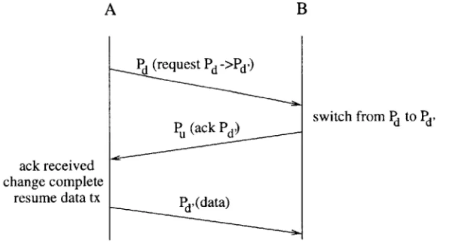
A B Pd (request Pd~>*d') switch from Pd to Pd' Pu (ack Pd ) ack received change complete
resume data tx P ,(data)
Figure 3-2: Basic protocol to modify a downstream link. Message format: link(message)
messages. A typical sequence, with host A initiating a change in its downstream link, is:
" Request. A sends a message over Pd requesting a change from Pd to Pd,.
" Acknowledge. B receives the message, changes its reception code from Pd to
Pdr, and sends an acknowledgment over P,. This acknowledgment informs host
A that it is ready to receive data over the new link.
* Link established. A receives the acknowledgement, and the new link is
es-tablished. A can now resume data transmission using Pd,.
This protocol is similar to the three-way handshake used in establishing a TCP connection [8]. The difference is the underlying communication link in this protocol changes while the link in the TCP three-way handshake remains static. This change in the communication link midway through the protocol affects the handling of message losses.
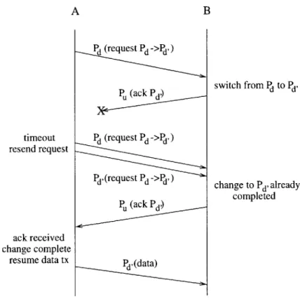
If either the request or its acknowledgement is lost, host A will not receive a
message back from host B. Thus, after a timeout, host A will have to retransmit the request. However, if the request is lost, host B is still listening on Pd, while if the ack is lost, B is listening on Pd'. Thus, if the timeout expires, host A will not know over which set of parameters to retransmit. The solution to this, shown in figure 3-3, is to retransmit the request on both channels, once on Pd and once on Pd'. Because host B is guaranteed to be listening on one of them, one of the two messages will be received if no further losses occur. If further losses do occur, the protocol continues in the same manner, with host A reaching its timeout and retransmitting on both channels. Upon receiving the acknowledgement, no further timeouts occur and data communication continues using Pd,.
During this message exchange, it is possible that host A may decide to change its request to a third alternative, Pd,, before the modification is complete. This may happen if conditions on Pd' are rapidly deteriorating and host A decides to bypass that channel. In terms of the protocol, this occurs when host A decides to issue a
A B timeout resend request ack received change complete resume data tx P (ack Pd) Pd (request Pd ->Id,) Pd (request Pd ->Pd) Pu (ack Pd) Pd (data) switch from Pd to Pd' change to Pd' already completed
Figure 3-3: Protocol to modify a downstream link, with lost messages and retrans-mission.
new request before it receives an acknowledgement for the old request. In this case, the same issue as above of host B's state applies; host B could be listening on either
Pd or Pd,. Thus, this new request to change to Pd, must be transmitted over both
Pd and Pd,. Also, in the event host A does not receive an acknowledgement of the
change to Pd., it does not know on which channel host B is listening. Thus, host A
must retransmit the request on three channels, Pd, Pd,, and Pd,.
While this extension to three alternatives may be useful, extending to even more alternatives becomes inefficient and unwieldy. If there are n alternatives, retransmis-sions of requests must be sent over n channels, requiring more time to retransmit the request and more memory to hold the software for all of the physical layer implemen-tations. Thus, the number of possible alternatives should be limited, and if the limit is reached, the current request must be allowed to complete.
3.2.2
Upstream Modification
Now, suppose that the initiating host wishes to modify its upstream link. Because it does not control the data flow through its upstream link, a similar message exchange to the above cannot be used. This is because a response may come over the new link, or data may still be transmitted over the old link.
A possible solution is for the initiating host to listen continuously for a response
over both links (the opposite of the first case). This would work, but it forces a host to run two receivers simultaneously since the data may come at any time. This is computationally expensive. A better solution is to force the downstream host to request a change in its downstream link. In this case, a host sends messages on two links serially since it has control over the data on its downstream link.
The protocol to execute a change in the upstream link is shown in figure 3-4. Host A, which is initiating the change, sends a message asking host B to request a modification in host A's upstream link. Once host B receives this message and replies
by beginning the basic protocol, the same message exchange as in the previous case
works.
A B
stop tx on Pu Pu (request Pu ->Pu) begin protocol switch from Pu to P, Pd(ackPu)
ack received change complete
resume data tx PF (data)
3.3
Convergence
1, Cn (n 0 '0 :3 1 Cr 0 CL *0 a, 1 ,,-6.. 1 54,.3 10- 10- 10 10 10-2Probability of message loss
10-1
Figure 3-5: Expected number of rounds until success as a function of message loss probability.
This protocol performs a modification reliably in the presence of message losses
by retransmitting requests. Although it is possible that the protocol never completes
because of message losses, this section shows that the protocol converges and is suc-cessful very quickly under a wide range of conditions.
Assuming that the upstream and downstream links are symmetric, each message has an independent probability p of being lost, and the probability that both a request and its acknowledgement are received successfully is q = (1 - p)2. This protocol is
successful when the first request/acknowledgement pair is successfully communicated. Thus, the probability distribution of number of request/ack pairs that are transmitted
before convergence is a geometric distribution with parameter q, i.e.:
Pr[success in n req/ack rounds] = (1 - q)f- q
From the properties of the geometric distribution:
1 1
E[req/ack rounds until success] - 2
q (1-p)
Pr[success within n rounds] = 1 - (1 - q)"
S1- (2p -p 2)n
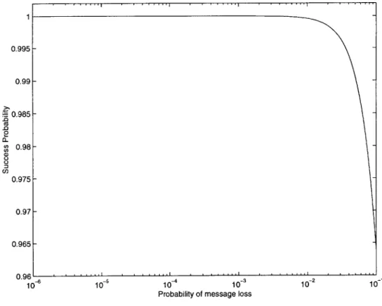
With each request transmitted, the probability of failure drops exponentially. Fig-ure 3-5 shows the expected number of rounds until the protocol succeeds as a function of the probability of message loss. Figure 3-6 shows the probability of successfully executing the protocol within two attempts. With a probability of message loss of
p = .01, the expected number of rounds until completion is 1.02 and the probability
of success within two attempts is 99.96%
3.4
Simultaneous Request Resolution
To the protocol, the design of a particular implementation of an adaptive wireless network is unknown. Thus, to the protocol, the source of modification requests can be arbitrary. For example, in a network with a single basestation and multiple mobiles, the basestation could be the sole initiator of modifications, but in a decentralized network of mobiles, each individual host may request its own changes. In the second example, either host on the ends of a link may request a modification at any time, and it is possible that both may request changes at the same time. However, only one change can be executed at a time, so there must be a provision in the protocol to resolve any simultaneous request (collision).
A collision is detected when a host that is listening for an acknowledgement to
0.985-en Ca 0 CL Co 0.98-=3 C.) 0.975- 0.97- 0.965-0.96 'I. 10 10 10 10 10 10
Probability of message loss
Figure 3-6: Success probability after two attempts of the protocol as a function of message loss probability.
one end of the wireless link, it is likely that a collision was also detected at the other end. Since all requests are treated equally, there is no provision for one host to defer to another in the event of a collision, and each host will attempt to get its request serviced. Thus, to avoid "livelock", where each host retransmits, resulting in another collision and repeating the process, the protocol introduces randomization. When a collision is detected, the host ignores the incoming request, cancels its previous outgoing request and waits a random length of time before retransmitting.
The remainder of this section focuses on the two node case. When extending to three or more nodes, the solution is the same; since only one node can modify the physical layer at a time, in the event of a collision, a randomization mechanism is used to determine which node is allowed to proceed. Since the analysis of such situations is complicated, the two node case is analyzed in-depth to provide insight on the issues involved in this type of randomized solution.
There are two cases to consider: both hosts receive requests and notice the col-lision, or only one host notices the collision. When both hosts notice the colcol-lision, both will ignore the request, and each host will wait a random amount of time before retransmitting its request. Since each waiting time is random, it is likely that one host will retransmit its request before the other host.
When only one host notices the collision, the two hosts are asymmetric. Suppose that host B notices the collision. Host B is waiting a random amount of time before retransmission, while host A is awaiting an acknowledgement. Host A will eventually timeout and retransmit, but the deterministic nature of the duration of the timeout is undesirable. If host B waits the random amount of time and retransmits before host
A times out and retransmits, host A receives the request, notices a collision, ignores
the request, and begins waiting a random amount of time. Host B is now awaiting an acknowledgement, and the situation has not improved.
In order to ensure randomness at both hosts, after a timeout, the protocol waits a random amount of time before retransmitting a request. Thus, detecting a collision is effectively an immediate timeout. This simplifies the protocol because collisions do not have to be handled by a special case.
The interval from which the random wait duration is chosen is an important parameter. A larger interval reduces the probability that the retransmissions collide but increases the amount of time required to execute the protocol. A collision of retransmissions occurs when both hosts retransmit within a period of time equal to the delay between the transmission time and the reception time. This delay is half of the round-trip time from one host to the other host and back again.
3.4.1
Simplified Analysis
To determine the optimal interval from which the random wait duration is chosen, let us determine the probability that the retransmissions collide, given that no losses of retransmissions occur. Assume each host begins its random wait at the same time. This is the worst case, because if one host begins earlier, the overlap of the random wait intervals is smaller and the probability of a collision is smaller.
This random wait interval is also used after timeouts due to lost messages. Thus, the width of the interval affects the time between retransmissions, which is equal to the timeout plus a random number chosen from the interval. In order to decouple the determination of the optimal random wait interval for collisions and the determination of the optimal time between retransmissions, we can determine the optimal random wait interval independently and then adjust the timeout such that the expected value of the sum of the timeout and the random number is optimal.
Let D be the delay between the transmission and reception times, and let r1 and
r2 be the random wait durations for the two hosts that are chosen uniformly from 0
to R. In practice, D is not constant, so this analysis uses D to represent the expected value of the delay. A collision occurs when fr1 - r2j < D.
For a given ri:
r +D if 0 < r1 < D
Pr[|r1- r2 < D] = D if D < ri < R - D
R-rl+D if R - D < r
1 < R
Evaluating over all values of ri, we get:
2. D D2 Pr[collision of retransmissions] Pc = R R
R R2
We want to minimize the expected amount of time spent in resolving a collision. Let us use the following simplified model for collision resolution that does not take into account the potential differences in waiting time between successes and failures:
" With probability 1 - Pc, a random wait time expires, a delay of D is incurred,
no collision occurs and the change is completed.
" With probability Pc, a random wait time expires, a delay of D is incurred, a collision occurs, and another attempt is made at resolving the collision.
If TCR is the time to resolve a collision, the following recurrence describes TcR:
TCR = random wait + D + Pc -TCR
TR =random wait + D S1- Pc
(3.1)
Thus, the expected time to resolve a collision, E[TCR], is:
E[TCR] E[random wait] + D
E[TcI --
P
R/2±D
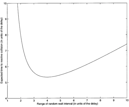
Figure 3-7 is the graph of equation 3.2. When the range R is very small, the expected TcR is large since the probability of a collision is very high. When R is large, the probability of a collision is low, but the expected TcR is large because the random wait takes a long time to complete. The minimum expected time to resolve
a collision occurs when R = 4D.
3.4.2
Simulation
The previous section left out several factors which facilitated a straightforward anal-ysis of the resolution of collisions. In particular, the analanal-ysis above did not take into account message losses or the potential offset in the times at which each host begins its random wait. Also, this analysis assumed that the expected waiting time per attempt was constant, regardless of whether the attempt succeeded or resulted in another collision. This simplified analysis resulted in a rough estimate of the op-timal value of R and also provided insight into the factors that affect the amount of time required to resolve a collision. However, in order to obtain a more realistic optimal value of R, the three factors that are mentioned above were incorporated into a simulation of the collision resolution.
One trial of this simulation involved setting up the initial collision, selecting ran-dom wait times, and determining if either of the retransmissions were lost. If so, or if
10 9-C 0 CO) 8-6 7-0 0 0 E C-) W 5 --4 1 2 3 4 5 6 7 8 9 10
Range of random wait interval (in units of the delay)
Figure 3-7: Expected time to resolve a collision as a function of the range of random wait times. All times in units of D.
the retransmissions resulted in another collision, the process of selecting random wait times repeats until no collision is detected. The time to resolve a collision is defined to be the amount of time elapsed from the moment the first host receives a conflicting request to the moment a host receives the first non-conflicting request, which results in an acknowledgement.
Figure 3-8 is the average time to resolve a collision reported by the simulation over a range of R and p values, where p is the probability of a message loss. For each R value in increments of .1D from 1.5D to 1OD, four different p values were used
(p = 0, 10-3, 10-2, 10-1), and for each p value, the simulation was run for 1 million
trials. Also, the timeout was set to 3D 1.
'The timeout is the amount of time, after transmitting a request, a host waits before retransmit-ting its request. The minimum amount of time it takes for an acknowledgement to reach the host is 2D + C, where D is the delay from one host to the other, and C is the time required to change the physical layer code. Using the approximation C ~ D, the acknowledgement is expected in 3D, so if
8.5 -~ p= 0 CO -0 7.5-0 S6.5-.2 > 6 -0 Z)5.5-E Et 5- 4.5-4 1 2 3 4 5 6 7 8 9 10
Range of random wait interval (in units of the delay)
Figure 3-8: Average time to resolve a collision as a function of the range of random wait times with different message loss probabilities. All times in units of D.
The shape of the curves produced by the simulation is the same as the one derived from the analysis in figure 3-7, and the average time to resolve a collision is minimized at about the same R value (R = 4.2D). This suggests that the additional parameters factored into the simulation do not greatly affect the optimal R. Since the value of R determines the probability of collision of two messages that are not lost and the resulting latency penalty, the probability of message loss does not affect the optimal R. Also, the potential offset in the times at which each host begins its random wait is small compared to R, and thus it does not affect the optimal R that much. Finally, the difference in the expected waiting time between collisions and successes is only observed on the very last attempt, since that is the only one that succeeds. Thus, it has no effect on the optimal R. However, it does affect the time to resolve a collision.
The protocol succeeds when one of the two hosts transmits D time before the other. The expected waiting time on this attempt is the smaller of the two waiting times, not the expected time of a single random wait, as was used in the simplified analysis. This distinction accounts for much of the difference in average waiting time between figures 3-7 and 3-8.
3.5
Summary
Since the physical layer of a wireless network link is completely implemented in soft-ware, modifications can be made by simply changing the code. However, both ends of the link must quickly switch to the same new physical layer to minimize the la-tency incurred by the modification. Messages must be passed between the two ends to identify the new physical layer (in terms of the software radio layering model), and to synchronize the modification. Also, since these control messages may be lost and multiple modification requests may be active at one time, a protocol must be used to ensure reliable modifications to the physical layer of the wireless link.
The protocol described in this section meets the desired criteria. In most cases, a simple message exchange involving one request and one acknowledgement is all that is needed to execute a modification. In an unfavorable environment, a retransmission scheme allows the modification to occur quickly in the presence of message losses. Also, since the mechanism to decide when modifications are necessary is unknown to the physical layer and multiple modification requests may be active, randomness is built into the system to ensure that the protocol completes the desired changes without deadlocking.
Chapter 4
System Design and
Implementation
Traditionally, a network interface device for both wired and wireless LANs consists of the physical device, such as an ethernet card or a WaveLAN device, and its device driver. The model of this type of architecture is shown in figure 4-1 (a). A user application accesses the network by interfacing with the top of the network stack. Information is processed down the network stack, and packets are communicated through the device driver and the hardware device to the network.
Our approach, also shown in figure 4-1 (b), takes many of the functions provided
by the hardware network interface device of the traditional approach and performs
them in software. User applications still access the network by interfacing with the top of the network stack, and a device driver still communicates with the bottom of the network stack. However, this device driver, instead of communicating with a piece of hardware, communicates with the software application that implements the physical layer. The processing that is normally performed on the network card is now done in software, and the interface to the physical world is provided by the GuPPI and the frontend. By implementing the physical layer in software, the functionality of the software-based network interface can be modified without changing the hardware. This chapter discusses the design of the software-based adaptive wireless network and its implementation in the SpectrumWare architecture. The scope of this design is
virtual network device application
user uservita
application application env. + I
control
wireless
User space User space network
Kernel space Kernel space
network network stack stack Software Hardware netwoSoftlink Softwared Hardware 8c network a. b.
Figure 4-1: Comparison of the (a) traditional approach with the (b) SpectrumWare approach.
limited to the infrastructure that executes a desired modification. The determination of which modifications are necessary is not addressed in this thesis but is discussed as future work in chapter 6.
4.1
Virtual Network Device Application
The SpectrumWare virtual radio system runs on any processor with a PCI bus running Linux. Applications, such as a wireless network device, reside in user space, and SpectrumWare extensions to the operating system allow access to system resources such as the network stack and physical devices.
The SpectrumWare wireless network device, as shown in grey in part (b) of fig-ure 4-1, consists of three main components:
* Softlink device. The Softlink device appears to the operating system as a network device and moves packets between the network stack and the virtual