Publisher’s version / Version de l'éditeur:
Vous avez des questions? Nous pouvons vous aider. Pour communiquer directement avec un auteur, consultez la première page de la revue dans laquelle son article a été publié afin de trouver ses coordonnées. Si vous n’arrivez pas à les repérer, communiquez avec nous à PublicationsArchive-ArchivesPublications@nrc-cnrc.gc.ca.
Questions? Contact the NRC Publications Archive team at
PublicationsArchive-ArchivesPublications@nrc-cnrc.gc.ca. If you wish to email the authors directly, please see the first page of the publication for their contact information.
https://publications-cnrc.canada.ca/fra/droits
L’accès à ce site Web et l’utilisation de son contenu sont assujettis aux conditions présentées dans le site LISEZ CES CONDITIONS ATTENTIVEMENT AVANT D’UTILISER CE SITE WEB.
14th Newfoundland Electrical and Computer Engineering Conference
[Proceedings], 2004
READ THESE TERMS AND CONDITIONS CAREFULLY BEFORE USING THIS WEBSITE. https://nrc-publications.canada.ca/eng/copyright
NRC Publications Archive Record / Notice des Archives des publications du CNRC : https://nrc-publications.canada.ca/eng/view/object/?id=16141dce-1a33-4096-b3ba-2a3fc8c5af7f https://publications-cnrc.canada.ca/fra/voir/objet/?id=16141dce-1a33-4096-b3ba-2a3fc8c5af7f
NRC Publications Archive
Archives des publications du CNRC
This publication could be one of several versions: author’s original, accepted manuscript or the publisher’s version. / La version de cette publication peut être l’une des suivantes : la version prépublication de l’auteur, la version acceptée du manuscrit ou la version de l’éditeur.
Access and use of this website and the material on it are subject to the Terms and Conditions set forth at
Design and implementation of a model scale lifeboat deployment
system
Design and Implementation of a Model Scale Lifeboat Deployment System
Wayne Pearson and Lawrence Mak Institute for Ocean Technology
National Research Council
Abstract
Design of a model scale lifeboat deployment system is presented. The lifeboat deployment system facilitates testing of physical model lifeboats. It is comprised of a controlling application and three core subsystems; a wave timer, two davits and associated controllers, and a boom and associated controller. The controlling application presents an intuitive graphical user interface and provides configuration and operational control of the entire system. The wave timer analyzes data from a wave probe to determine the optimum time a lifeboat should be launched. This process ensures the lifeboat lands on the least dangerous part of the wave phase. The wave timer and automated launch capability enable researchers to study the effects of deploying the lifeboat at differing wave phases. The davits and controller subsystem raises and lowers the lifeboat at user specified controlled rates. The boom and controller
subsystem orients and propels the lifeboat away after launch. The angle of the boom, which is dependent on boom load, is continually adjusted by a simple closed loop feedback system. Discussion of the design requirements and
implementation of this system are presented.
INTRODUCTION
This paper focuses on the design and implementation of a model scale lifeboat deployment system (LDS). The LDS was developed to enable researchers to investigate two marine evacuation systems at the Institute for Ocean
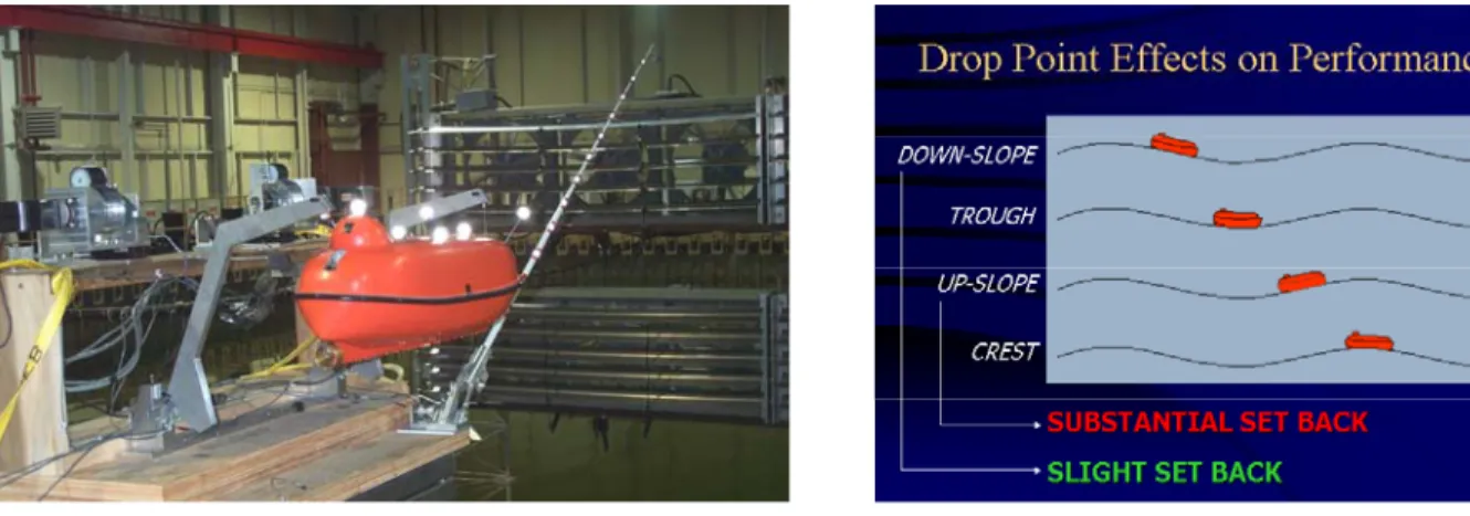
Technology. Tests were done with the conventional twin falls davit launch system and with a similar system fitted with a flexible boom. The performance of both systems was evaluated as a function of weather conditions and platform integrity. The weather conditions ranged from calm to severe storms and the platform integrity from intact to damaged. In addition, the effects of deploying the lifeboat at differing wave phases was examined. The wave phases of interest were down-slopes, troughs, up-slopes, and crests. (Note: It is very hard to deploy on the down-slope of a wave using the davit system due to differences in the speed of travel of the wave and the deployment speed of the lifeboat.)
Figure 2. LDS Target Wave Phases Figure 1. LDS Deployment System
The design of an LDS to facilitate model scale lifeboat testing dictates that a number of factors are taken into consideration. The system should be safe, easy to operate, and the user interface must be intuitive. The lifeboat should be simple to deploy and it should be a trivial matter to reattach the lifeboat to the davits and boom afterward. Recovery from anticipated failures such as cable breaks should be quick and painless. The capability to recalibrate system components must be provided. Finally, the user should be able to export and import system application settings. Proper attention to these requirements facilitates personnel training, reduces the incidence of accidents and errors, and enables testing to be performed quickly and economically. In fact, the effort required to address these issues often comprises a significant portion of the total development time.
SYSTEM DESIGN ISSUES
The LDS system is comprised of a controlling application and three core subsystems; a wave timer, two davits and associated controllers, and a boom and associated controller. The following sections focus on design issues concerning the controlling application and each of the three subsystems.
LDS Controller Application
The LDS software application provides an intuitive graphical user interface, GUI, to enable configuration and operational control of the entire system. The LDS application employs a modular software architecture with individual components to access the data acquisition hardware, wave timer hardware, and motor controllers. The modular software architecture facilitates unit testing and it promotes code reuse by separating clearly delineated tasks into separate self-contained modules. For example, the data acquisition component can be tested separately from the other modules and it can easily be used by another software application. The GUI updating code is contained in a timer module that executes at a frequency of 10 Hz. This design methodology separates the GUI updating code from the operations code, reducing clutter, facilitating code maintenance, and improving code readability. The following section focuses on design issues related to the GUI.
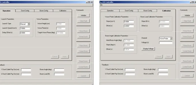
Figure 3. LDS Controller Application – Operation Tab Figure 4. LDS Controller Application – Calibration Tab
The LDS screen is divided into three regions; a Command Region with nine command buttons, a Feedback Region that is continually updated with relevant details on each davit cable and on the boom, and a Tabbed Dialog Region that presents four tabbed dialogs, Operation, Davit Config, Boom Config, and Calibration.
The Command Region has nine command buttons and these are grouped according to functionality; for example Raise Davits and Lower Davits appear together; these are the commands used most often and grouping them together reduces the likelihood of an error. Launch is located in its own section – again reducing the likelihood of an accidental launch. Each button’s enabled state is dependent on whether specific operations have been performed. Initialize is the only button enabled at system startup. Once the Initialize operation is performed, the Initialize button is disabled and the Home Boom and Home Davit buttons are enabled. After the Home Boom operation is complete, the Raise Boom and Lower Boom buttons are enabled; similarly the Raise Davits and Lower Davits buttons are enabled after the Home Davits operation. Finally, the launch button is enabled only after the system has been initialized, both the boom and the davits have been homed, and the davits have been moved to the lifeboat stowed position. Note that Raise and Lower buttons are colored red and their text is modified to “Stop” while they are active. This button text and coloring visually cues the user that the red button is the “Abort” button.
The LDS application uses four tabbed dialogs, Operation, Davit Config, Boom Config, and Calibration to group parameters corresponding to four major functional areas. The use of tabbed dialogs reduces screen clutter and enables logical groupings and presentation of system parameters.
The Operation tab enables the user to specify operational parameters such as Launch Type (Manual, Auto, or Auto Freefall), Launch Speed, Wave Period, and Target Wave Phase. Note that the Auto Freefall mode enables release of the lifeboat at a specified distance above the Target Wave Phase.
The Davit Config tab enables the user to adjust parameters specific to the Davits and Controller subsystem. The Raise Speed and Lower Speed indicate how fast the davit cables are reeled in and payed out, respectively. The Still-Water Line (SWL) Distance indicates the distance from the bottom of the lifeboat to still water when the Davit cables are payed out to the zero position. The SWL Distance is obtained simply by homing the davits and then paying out cable until the bottom of the lifeboat just touches the water. The Davit cable payout at this location, which is viewable in the feedback area, is used as the SWL Distance. The Embark Position is the davit cable payout at which persons enter the lifeboat (in our instance persons enter the lifeboat when the davit arms come into contact with the support platform). The Embark Wait Time is the time in seconds that the lifeboat stays at the Embark Position. Finally, the Freefall Distance is the distance above the target wave phase at which the lifeboat is released. Note that the Freefall Distance applies only to an Auto Freefall launch. Since the Freefall Distance is a somewhat “dangerous” parameter, we specify it in the Davit Config tab rather than the Operation tab to reduce the chance of accidentally modifying the Freefall Distance.
The Boom Config tab enables the user to adjust parameters specific to the Boom and Controller subsystem. The Raise Speed and Lower Speed indicate how fast the boom should be raised and lowered, respectively. The Track Enable Position specifies a Davit Cable payout (or threshold) above which boom tracking is always enabled. This parameter is used to prevent accidental damage to the boom when raising the lifeboat. When a lifeboat is first attached to the LDS, both the davit cables and the boom are in a lowered position. Additionally,
boom tracking is disabled to allow the boom to remain at the lowered position without the presence of a load. When the user raises the lifeboat, the boom initially remains at its lowered position until the davit cable payout reaches the Track Enable Position. At this point, boom tracking is enabled and the boom begins to rise (since it is not experiencing a load) thus protecting the boom from any undue stresses. Finally the Speed Windowing Function, Window Size, and Tracking Slope are used to control the speed, responsiveness, and fluidity of boom motion. The Calibration tab enables the user to calibrate the wave probe, boom load, and boom angle. To calibrate a load cell the user chooses the Load Cell channel, attaches a known weight (load) to the load cell, and records the displayed voltage. This procedure is repeated for a set of known weights (3 to 5) and each load and its corresponding voltage is recorded in an Excel spreadsheet. A line is then fitted to these values to obtain calibration coefficients that are entered into the corresponding fields in the calibration tab.
Note that all settings are entered in real world units (eg. the boom raise and lower speeds are entered in deg/sec rather than esoteric machine units) to enable the operator to more easily comprehend the effect of a setting change. In addition, the LDS application verifies the correctness of input parameters thus minimizing the risk of entering an invalid parameter. Finally, settings that do not apply to a given operation are grayed out and disabled. For example, the Wave Height, Wave Period, and Target Wave Phase parameters in the Operation tab are not applicable when a manual launch is selected so the LDS application visually and functionally cues the user that this is the case. All application settings can be saved to a configuration file for later import into the LDS application. When the LDS application is shut down, all current application settings are saved. The LDS application loads these settings when it is restarted. Current application settings can be modified either by specifying new settings via the tabbed dialogs or by importing a previously saved configuration file.
Davits and Controller Subsystem
The Davits and Controller Subsystem (DCS) is the heart of the entire system and it is responsible for all of the heavy lifting. Several operations are applicable to this subsystem; a homing operation establishes the origin of the davit cable payout coordinate system, raise and lower operations reel in and pay out the davit cables respectively, and
launch initiates a lifeboat launch. In addition, the lifeboat can be released to freefall at a specified distance above the Target Wave Phase. Several issues arose during the design of this subsystem. How will the origin of the DCS coordinate system be established? What mechanisms will be put in place to make sure that the controller does not try to reel in the davit cables too far? How should the system be designed to facilitate ease of cable installation and repair of cable breakage? These issues relate to safety and turnaround time. The system should be safe to use and maintenance and operational activities should be quick and easy to perform. Tank time is precious!
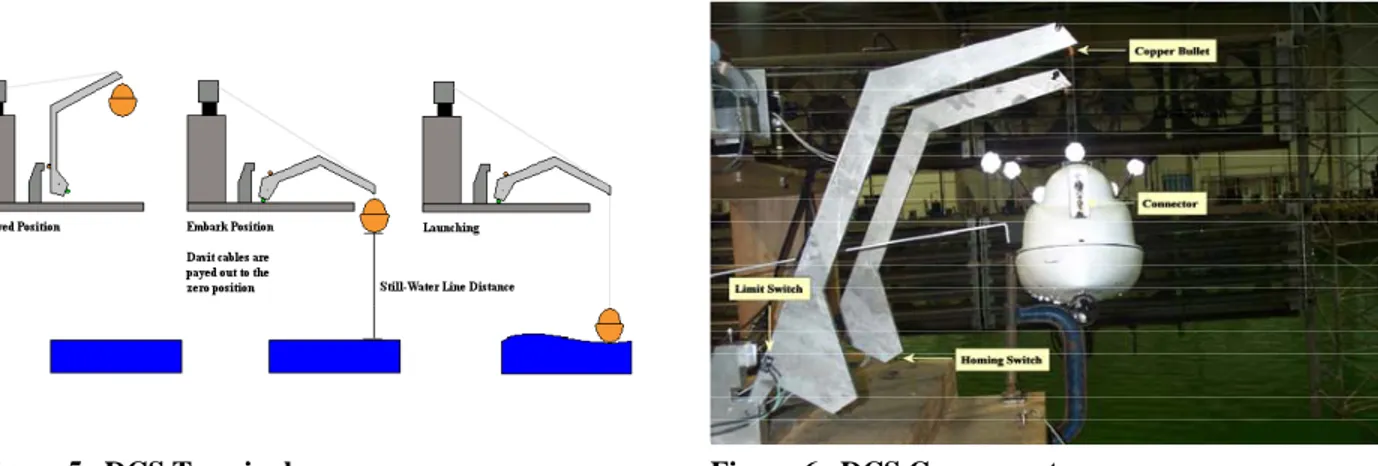
The DCS establishes its coordinate system by performing a homing operation. The LDS application monitors the state of a normally open switch (homing switch) located on the bottom of the davit arm. This switch is pushed closed when the bottom of the davit arm comes into contact with the support platform. Alternatively, when the davit arm is raised above the support platform, then the switch is opened. During a homing operation, the davit arm is first moved to a position above the support platform, if required. This action sets the homing switch to the open state. The davit is then lowered until it just rests on the support platform, closing the homing switch. This operation establishes the origin of the DCS coordinate system. Cable take up beyond this point is expressed as a negative value while cable pay out beyond this point is expressed as a positive value.
The DCS protects against reeling in the davit arms too far by placing a limit switch contact at a point beyond which they should not be reeled in. If the limit switch is activated (note that this should not happen in normal operation) then the current davits controller operation is aborted.
A cable is installed by first attaching it to a helically grooved drum and winding a few turns around the drum. The helical groove combined with a pinch roller ensures that the cable is evenly distributed across the drum as it is reeled in and payed out. The free end is then pulled through a hole in the davit arm, a copper bullet is crimped to the cable at a point immediately below the hole, and a connector is attached to the free end of the cable. To repair a broken cable, one simply cuts off the damaged section, pulls a new section of wire through the hole in the davit arm, and reattaches the copper bullet and connector. Note that the copper bullet has a larger diameter than the hole in the davit arm and that the copper bullet and connector move with the cable. If a davit arm is not fully extended, it rests on the copper bullet and is lifted as the cable is reeled in and lowered as the cable is payed out. Once the cable is
reattached, the davit arms are homed independently to reestablish the origin of the DCS coordinate system. Note that homing each davit arm independently does much to facilitate the repair of damaged cables. Since each davit arm searches for its home position independently, cables can be of different lengths; the only thing that matters is that both are long enough to accommodate the maximum pay out. Once the homing operating is complete both davit arms can be configured to operate as a single unit.
Figure 6. DCS Components Figure 5. DCS Terminology
Note that the DCS outputs comprise one analog channel, which reflects the amount of cable paid out over time, and two digital channels. The first digital channel is used for diagnostic purposes and it outputs both the time at which the launch system was synchronized with a wave crest and, in the event of a freefall launch, the time at which the a release signal was sent to the lifeboat. If the launch type is Auto Freefall, the second digital channel delivers the release signal to the lifeboat.
Wave Timer Subsystem
The accurate and consistent deployment of a lifeboat on a target wave phase is a primary requirement of the LDS. Variances in operator response time make it impossible to consistently achieve this goal without the use of an automated control system. The Wave Timer Subsystem (WTS) was developed to fulfill this requirement. The specialized nature of this component dictated innovative in-house solutions and equipment. Normally, off the shelf solutions and equipment are used, where possible, to take advantage of potential cost, time, and development savings. Full control of the design process ensured that the resultant wave timer conformed to system requirements and that it integrated seamlessly with the rest of the system. The WTS was developed jointly between the Institute for Ocean Technology and Memorial University and patent applications have been filed in both the U.S. and Canada (U. S. Patent Application # 10/369536, Canadian Patent Application # 2419707).
∑
= =+
1..n it
*
i
t
t
ci c wpThe WTS monitors an analog signal from a wave probe and combines this information with user specified launch parameters to ensure a successful deployment. A wave probe located beside the launch platform outputs an analog signal that represents the wave elevation over time. This signal is analyzed to accurately determine when a wave crest passes under the launch platform. If the generated waves are regular (periodic) waves, a wave crest passes under the launch platform at each integer multiple of the wave period following the arrival of the initial wave crest. If tc represents the time that the detected wave passed under the launch platform and twp represents the wave period
then the times subsequent waves pass under the platform can be computed using the formula The remaining wave timer inputs are the Stowed Position, Lower Speed, Embark Position,
Embark Wait Time, Launch Speed, SWL Distance, Wave Height, Wave Period, Target Wave Phase, and, if applicable, Freefall Distance. Many of these parameters are discussed in the Graphical User Interface section; however, the Lower Speed and the Launch Speed bear further explanation. During a launch the Lower Speed is the cable pay out rate used when the lifeboat moves from the Stowed Position to the Embark Position. The Launch Speed is the cable pay out rate used when the lifeboat moves from the Embark Position to the deployment location. Prior to commencing a series of model scale lifeboat system deployment tests, the LDS Application is started, the system is initialized and both the davits and the boom are homed. The lifeboat is attached to the LDS and the SWL Distance is determined using the process described earlier. Note that all sensors are calibrated prior to the start of a series of tests. Once these tasks are completed the user can began the test series. To initiate a launch the operator raises the lifeboat to the stowed position and clicks the Launch button. At this point the wave maker is started and a series of waves are generated. Once the height of these waves reaches the proper level, the LDS starts a timer, acquires a set of wave samples, and analyzes it to determine the time (tc) at which a wave crest passes under the
launch platform. Once tc is determined, a launch time that guarantees deployment on the target wave phase is
computed. After determining the launch time, WTS delays the launch until it is synchronized with a wave crest passing beneath the launch platform and then continues it to completion.
Note that the WTS can be extended to operate in an environment with irregular (non-periodic) waves by adding multiple wave probes and using additional wave timer support software.
Boom and Controller Subsystem
The Boom and Controller Subsystem (BCS) ensures that the lifeboat is oriented in the proper direction to escape a disabled vessel/platform. In addition, the boom lends a propulsive assist to the lifeboat; a quick upward motion of the boom at the instant of release pulls the lifeboat forward, away from the disabled vessel/platform.
When designing a system or component, an investigation into previous work of a related nature can yield significant cost and time savings. Effort that had gone into developing a BCS for an earlier project contributed greatly to the development of the new BCS. The motor controller hardware and boom assembly from the earlier project were appropriated for the new BCS. The motor controller (Aerotech Unidex 500) has several modes of operation; one of which enables the user to continuously update the direction and speed of the associated motor(s).
Once the boom was instrumented with a load cell to measure load and a rotary type potentiometer to measure angle, our task was reduced to developing controller software that ensured that the boom’s motion adhered to a specified Boom Angle vs. Boom Load curve.
This requirement is best written as
angledeg = f(loadNewtons)
The boom controller developed for the LDS conforms to this requirement and is a simple closed loop feedback system modeled after the technique a driver uses when approaching a stop sign. If the driver is a long way from the stop sign, he drives at normal speed. As he approaches the stop sign he reduces speed in a controlled manner so that he comes to a graceful stop.
We use a windowing function to control the velocity of the boom. The windowing function returns a
speed multiplier that is proportional to the boom’s distance from the target angle. The speed multiplier ranges between 0 and 1 and the closer the boom to the target angle, the lower the value.
The windowing function is best expressed as
speedMultiplier[0..1] = f (distanceFromTargetAngledeg)
The boom’s velocity is calculated by the formula below
velocitydeg/sec = direction * normalOperatingSpeeddeg/sec * speedMultiplier
In our instance, the speed multiplier function is simply a linear function that returns the value 1 until the boom moves closer than ½ the maximum distance to the target angle; as the boom continues to move closer the speed multiplier ramps down until it reaches zero at the target angle.
The BCS has an oscillatory characteristic; a decrease in boom load as the boom approaches the target angle can necessitate a change in direction and a move to a new target angle. As the boom moves toward the new target angle an increase in boom load may necessitate another change in direction and a move toward yet another target angle. If the load sampling rate is high enough, a record of the most recent boom loads can be maintained and a target angle can be computed based on the mean (or median) of these values. This filtering operation tends to smooth the movement of the boom. Note that too large a window size can result in sluggish boom performance since older samples are included in the mean (or median) calculation. We find that a window size of 3 to 5 samples works well for a boom operating speed of 30 deg/sec and a sampling frequency of 40 Hz.
CONCLUDING REMARKS
In order for a system design and implementation to give a favorable result, a clear view of the system requirements, both application specific and non-application specific, is essential. In our case application specific requirements included an LDS with the ability to consistently deploy a lifeboat on a target wave phase and a boom whose motion was responsive to the current boom load. Non-application specific requirements, which are applicable to many systems, included ease of use, a simple operator interface, and safety features. Other considerations included using off the shelf components and leveraging existing equipment and solutions to realize time and cost savings. Our design methodology and adherence to the above guidelines resulted in a system that worked well, satisfied the specified requirements, was safe and easy to operate, and required minimal operator training.
ACKNOWLEDGEMENTS
National Research Council Canada - Institute for Ocean Technology Memorial University of Newfoundland
Canadian Association of Petroleum Producers Natural Resources Canada
Transport Canada