Publisher’s version / Version de l'éditeur:
Vous avez des questions? Nous pouvons vous aider. Pour communiquer directement avec un auteur, consultez la première page de la revue dans laquelle son article a été publié afin de trouver ses coordonnées. Si vous n’arrivez pas à les repérer, communiquez avec nous à PublicationsArchive-ArchivesPublications@nrc-cnrc.gc.ca.
Questions? Contact the NRC Publications Archive team at
PublicationsArchive-ArchivesPublications@nrc-cnrc.gc.ca. If you wish to email the authors directly, please see the first page of the publication for their contact information.
https://publications-cnrc.canada.ca/fra/droits
L’accès à ce site Web et l’utilisation de son contenu sont assujettis aux conditions présentées dans le site LISEZ CES CONDITIONS ATTENTIVEMENT AVANT D’UTILISER CE SITE WEB.
CIB World Building Congress 2004 [Proceedings], pp. 1-14, 2004-05-01
READ THESE TERMS AND CONDITIONS CAREFULLY BEFORE USING THIS WEBSITE.
https://nrc-publications.canada.ca/eng/copyright
NRC Publications Archive Record / Notice des Archives des publications du CNRC : https://nrc-publications.canada.ca/eng/view/object/?id=f1b51634-3402-4d54-817b-7ca5472359ff https://publications-cnrc.canada.ca/fra/voir/objet/?id=f1b51634-3402-4d54-817b-7ca5472359ff
NRC Publications Archive
Archives des publications du CNRC
This publication could be one of several versions: author’s original, accepted manuscript or the publisher’s version. / La version de cette publication peut être l’une des suivantes : la version prépublication de l’auteur, la version acceptée du manuscrit ou la version de l’éditeur.
Access and use of this website and the material on it are subject to the Terms and Conditions set forth at
Field investigation and laboratory testing of exposed vinyl roof
systems
Field investigation and laboratory testing of exposed
poly(vinyl chloride) roof systems
Whelan, B.J.; Graveline, S.P.; Delgado, A.H.;
Liu, K.K.Y.; Paroli, R.M.
NRCC-47700
A version of this document is published in / Une version de ce document se trouve dans: CIB World Building Congress 2004, Toronto, ON., May 2-7, 2004, pp. 1-14
Field Investigation and Laboratory Testing of
Exposed Poly(Vinyl Chloride) Roof Systems
Brian J. Whelan1, Stanley P. Graveline1, Ana H. Delgado2, Karen KY Liu2 and Ralph M. Paroli2
1
Sarnafil USA, 100 Dan Road, Canton, MA 02021, USA
2
National Research Council of Canada – Institute for Research in Construction, 1200 Montreal Road, Bldg. M20, Ottawa, ON K1A 0R6 Canada
Abstract
In 1999, a major manufacturer of thermoplastic membranes set out to “quantify and qualify” how their oldest roofs in the United States and Canada were performing. This information was critical for their Life Cycle Cost Data. The process was as follows: This manufacturer reviewed their internal project data base and project files to determine the oldest project in each of their regions. The regions attempted to contact each owner of the building. Approximately 70% of the owners were contacted because some of the buildings were vacant or torn down. A survey was sent to the building owners of 70 of their oldest projects in the U.S and Canada (range 17-22 years old). Some surveys were filled out over the telephone. The response rate was 63%. All surveys were collected and statistics created.
In 2001, the manufacturer sampled 25 of these projects in all regions and climates and invited roof consultants and architects to participate in field investigations and roof sampling. The specific roofs sampled in these different regions and climates were selected solely as a matter of convenience. That is, the roofs were samples when owners provided the manufacturer permission to do so and when the costs of accessing the selected roofs were reasonable. Samples were packaged and sent to the National Research Council of Canada (NRCC). The NRCC tested samples according to ASTM D4434 [1] (where appropriate) for thickness, tensile strength, elongation, linear dimensional change, low temperature flexibility and seam strength. It should be noted that D4434 [1] was established in 1985 and was the first ASTM standard for any single ply roof membrane in the U.S. Most of the roofs sampled were installed before the standard even existed. All of the roofs investigated and sampled were found to be in good shape. No immediate maintenance or repairs were needed. After sampling all of the existing roof membranes could be easily patched by hot air welding.
The laboratory testing confirms that although the products tested lost some of their initial physical properties (as expected), they generally held up well compared to the standard minimum values for testing new PVC roofing membranes according to ASTM D4434 [1]. It is important to note, however, that some of these membranes, which had been tested in the NRC laboratory about 15 years ago, exceeded the minimum requirements of the ASTM D4434 [1]. This is an interesting point because as materials age/weather, their properties are expected to degrade.
Introduction
Poly(vinyl chloride) – also known as vinyl -- is one of the most versatile thermoplastics in use today. It is produced by polymerization of vinyl chloride monomer, a gas produced by the reaction of ethylene with oxygen and hydrochloric acid. This reaction produces a chemical bond that is saturated and hence, highly inert and strong. In its basic form, PVC resin is a rigid substance to which plasticizers, stabilizers, and other components must be added to provide the desired properties for the PVC’s intended use. It has been used in roof coverings since the 1960’s. The basic formula for today’s PVC roof membranes is shown in Table 1.
There are three types of PVC roofing sheets: unreinforced, unreinforced with fibres or fabrics that act as carriers, and reinforced sheets that contain fibreglass and/or polyester fibres or
fabrics. Reinforcements may be composed of woven polyester or woven or unwoven glass fibers. Polyester reinforcement is used to increase the membrane’s resistance to tearing in the wind. Polyester reinforcement is used mainly for sheets that are going to be fastened mechanically, while fibreglass reinforcements are used for adhered systems. Fibreglass reinforcement is used mainly for dimensional stability. The carrier facilitates manufacturing and may add to the dimensional stability of the sheet. Reinforcement provides tensile and other properties. Generally, unreinforced sheets are produced by calendering or extrusion. Reinforced sheets can be produced by laminating two plies of unreinforced sheet with a layer of reinforcement between them or by a coating process.
Table 1 Typical composition of a generic PVC roofing membrane.
Ingredients % by Mass Function
PVC resin 50 – 55 Basic material (powder or granular)
Plasticizers 25 – 35 Impart flexibility
Inorganic solids 5 – 10
Increase dimensional stability and mechanical properties
Pigments 0.5 - 1.0 Provide color and UV stability to the
PVC compound Processing oils
and biocides
0.5 - 1.0 Improve processing and resistance to
biological attack
Stabilizers 2 – 3
Provide resistance to heat and light during manufacture and use
Note: Based on technical notes and some related patent specifications
One main advantage of PVC sheets is that the entire roof membrane can be joined by welding the joints with solvent or with air heated to 425 °C. This membrane can also be welded to metal flashing that has been factory-coated with PVC. The result is a continuous roofing assembly. PVC sheets remain flexible at temperatures as low as -40 °C. They are ideal for re-roof and repairs, because of their high permeability. Moreover, white reflective vinyl membranes contribute to reducing urban heat island effects, can be produced in a wide spectrum of colors to meet desired aesthetic features of building, have high resistance to puncture and impact and have excellent resistance to flame exposure and subsequent fire propagation.
Loss of plasticizers has been a concern with certain PVC roofing products [2, 3], as it caused embrittlement in the PVC sheets. This can be controlled by using high molecular weight plasticizers that have less of a tendency to volatilize or migrate out of PVC resin. Certain PVC roofing membranes utilizing a very stable formulation have over 40 years experience in Europe and close to 25 years throughout North America. Moreover, today all sheets are reinforced so that in case of cracking of the membrane, a local repair should suffice.
Vinyl roofing membranes should meet ASTM D4434 [1] or CAN/CGSB 37.54 recognized North American standards. PVC sheets have good resistance to industrial pollutants, bacterial growth and extreme weather conditions. Minor damage to the sheet during installation or in-service can be easily repaired by patching the hole using heat or solvent. PVC is incompatible with bituminous materials therefore care must be taken to avoid direct contact with asphalt.
Objectives
Physical properties of all roof systems change with age and outdoor exposure. The change in physical properties of a roof membrane may be a result of many factors. A few factors that may affect the physical properties of a vinyl membrane include chemical formulation stability, thickness of the polymer, reinforcement, method of manufacturing, geographic location, heat and ultra violet radiation exposure, other products used in conjunction with the membrane and
roof slope. The purpose of this investigation is to study the performance and physical properties of reinforced PVC membranes throughout North America. This information is critical for true life cycle costing and analysis.
Methodology
In 1999, a major manufacturer of thermoplastic membranes set out to “quantify and qualify” how their oldest roofs in the United States and Canada were performing. This information was critical for their Life Cycle Cost Data. The process was as follows: This manufacturer reviewed their internal project data base and project files to determine the oldest project in each of their regions. The regions attempted to contact each owner of the building. Approximately 70% of the owners were contacted because some of the buildings were vacant or torn down. A survey was sent to the building owners of 70 of their oldest projects in the U.S and Canada (range 17-22 years old). Some surveys were filled out over the telephone. The response rate was 63%. All surveys were collected and statistics created.
In 2001, the manufacturer sampled 25 of these projects in all regions and climates and invited roof consultants and architects to participate in field investigations and roof sampling. The specific roofs sampled in these different regions and climates were selected solely as a matter of convenience. That is, the roofs were samples when owners provided the manufacturer permission to do so and when the costs of accessing the selected roofs were reasonable. Samples were packaged and sent to the National Research Council of Canada (NRCC). The NRCC tested samples according to ASTM D4434 [1] (where appropriate) for thickness, tensile strength, elongation, linear dimensional change, low temperature flexibility and seam strength. It should be noted that D4434 [1] was established in 1985 and was the first ASTM standard for any single ply roof membrane in the U.S. Most of the roofs sampled were installed before the standard even existed. All of the roofs investigated and sampled were found to be in good shape. No immediate maintenance or repairs were needed. After sampling all of the existing roof membranes could be easily patched by hot air welding.
Thickness Measurements
The material adhered on the G-designated samples were removed by either peeling slowly by hand or scraping carefully using a brass putty knife. Care was taken during the material removal to minimize any damage to the samples. (Note: For definitions regarding Type and Grade
please refer to Reference 1.)
1. The thickness of the fibreglass-reinforced roofing membranes (ASTM Type II Grade 1) was measured according to ASTM D638 [4]. A hand held micrometer with a ratchet was used which has an accuracy of 0.025 mm (0.001 in.). The diameter of the contact foot
was 6.35 mm (0.250 in.) and a pressure of 25kPa (3.6 psi) was used. Five
measurements were taken at randomly selected points over the sample surface. The average and standard deviation of the thickness are reported in Table 3.
2. The thickness of the polyester reinforced roofing membranes (ASTM Type III) was measured according to ASTM D751 [5]. A dead weight dial gauge that was graduated to read to 0.025 mm (0.001 in.) was used. The presser foot had a diameter of 9.52 mm (0.375 in). Five measurements were taken at randomly selected points over the sample surface. The average and standard deviation of the thickness are summarized in Table 3.
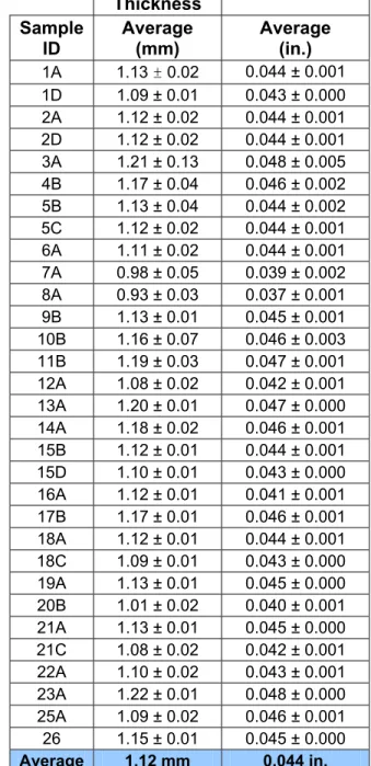
The roofing membranes that met the minimum thickness requirement for new membranes (1.14 mm) as stated in ASTM D4434 [1] are 3A, 4B, 10B, 11B, 13A, 14A, 17B, 23A and 26. Samples 7A and 8A, which may have been Type IV membranes, were significantly below 1.14 mm. The other samples were very close to the thickness specified in ASTM D4434 [1] for Type II Grade I and Type III membranes.
Table 2
Summary of all PVC samples received.
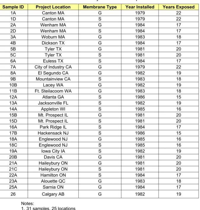
Sample ID Project Location Membrane Type Year Installed Years Exposed
1A Canton MA G 1979 22 1D Canton MA S 1979 22 2A Wenham MA G 1984 17 2D Wenham MA S 1984 17 3A Woburn MA G 1983 18 4B Dickson TX G 1984 17 5B Tyler TX G 1981 20 5C Tyler TX S 1981 20 6A Euless TX S 1984 17 7A City of Industry CA G 1979 22 8A El Segundo CA G 1982 19 9B Mountainview CA S 1983 18 10B Lacey WA G 1982 19 11B Ft. Steilacoom WA G 1983 18 12A Atlanta GA S 1986 15 13A Jacksonville FL S 1982 19 14A Appleton WI S 1985 16 15B Mt. Prospect IL G 1981 20 15D Mt. Prospect IL S 1981 20
16A Park Ridge IL S 1984 17
17B Hackensack NJ S 1986 15
18A Englewood NJ G 1985 16
18C Englewood NJ S 1985 16
19A Iowa City IA S 1982 19
20B Davis CA G 1981 20 21A Haileybury ON G 1981 20 21C Haileybury ON S 1981 20 22A Hamilton ON S 1984 17 23A Alouette QC G 1983 18 25A Sarnia ON G 1984 17 26 Calgary AB G 1982 19 Notes: 1. 31 samples, 25 locations
2. S refers to synthetic polyester reinforced, typically installed in mechanically fastened applications
3. G refers to fibreglass reinforced, typically installed in adhered applications 4. 12 refers to 1.2 mm or 47.4 mils in thickness
Tensile Properties
The tensile properties of the polyester reinforced roofing membranes were measured according to ASTM D751, Procedure B – Cut Strip Test Method [5]. The samples were cut into specimens of 25 mm X 150 mm (1 in. X 6 in.), using a utility knife with the aid of a plastic template. The specimens were tested in an Instron model 4502 machine with a gauge length of 75 mm (3 in.) at a constant crosshead speed of 300 mm/min (12 in./min). A minimum of five specimens were tested in both machine and cross directions.
The tensile properties of the glass reinforced roofing membranes were tested according to ASTM D638 [4]. The samples were cut into specimens using a dumb bell shaped die # C in a hydraulic press. The specimens were tested in an Instron model 4502 machine with a gauge
length of 65 mm (2.5 in.) at a constant crosshead speed of 50 mm/min (2 in./min). A minimum of five specimens were tested in both the machine and the cross directions.
Table 3
Summary of thickness results with single standard deviation
Thickness Sample ID Average (mm) Average (in.) 1A 1.13 ± 0.02 0.044 ± 0.001 1D 1.09 ± 0.01 0.043 ± 0.000 2A 1.12 ± 0.02 0.044 ± 0.001 2D 1.12 ± 0.02 0.044 ± 0.001 3A 1.21 ± 0.13 0.048 ± 0.005 4B 1.17 ± 0.04 0.046 ± 0.002 5B 1.13 ± 0.04 0.044 ± 0.002 5C 1.12 ± 0.02 0.044 ± 0.001 6A 1.11 ± 0.02 0.044 ± 0.001 7A 0.98 ± 0.05 0.039 ± 0.002 8A 0.93 ± 0.03 0.037 ± 0.001 9B 1.13 ± 0.01 0.045 ± 0.001 10B 1.16 ± 0.07 0.046 ± 0.003 11B 1.19 ± 0.03 0.047 ± 0.001 12A 1.08 ± 0.02 0.042 ± 0.001 13A 1.20 ± 0.01 0.047 ± 0.000 14A 1.18 ± 0.02 0.046 ± 0.001 15B 1.12 ± 0.01 0.044 ± 0.001 15D 1.10 ± 0.01 0.043 ± 0.000 16A 1.12 ± 0.01 0.041 ± 0.001 17B 1.17 ± 0.01 0.046 ± 0.001 18A 1.12 ± 0.01 0.044 ± 0.001 18C 1.09 ± 0.01 0.043 ± 0.000 19A 1.13 ± 0.01 0.045 ± 0.000 20B 1.01 ± 0.02 0.040 ± 0.001 21A 1.13 ± 0.01 0.045 ± 0.000 21C 1.08 ± 0.02 0.042 ± 0.001 22A 1.10 ± 0.02 0.043 ± 0.001 23A 1.22 ± 0.01 0.048 ± 0.000 25A 1.09 ± 0.02 0.046 ± 0.001 26 1.15 ± 0.01 0.045 ± 0.000 Average 1.12 mm 0.044 in.
Note: ASTM D4434 [1] Type II Grade 1 and Type III requirement is 1.14 mm (45 mils)
ASTM Type IV requirement is 0.91 mm (36 mils)
Polyester Reinforced Samples (ASTM Type III)
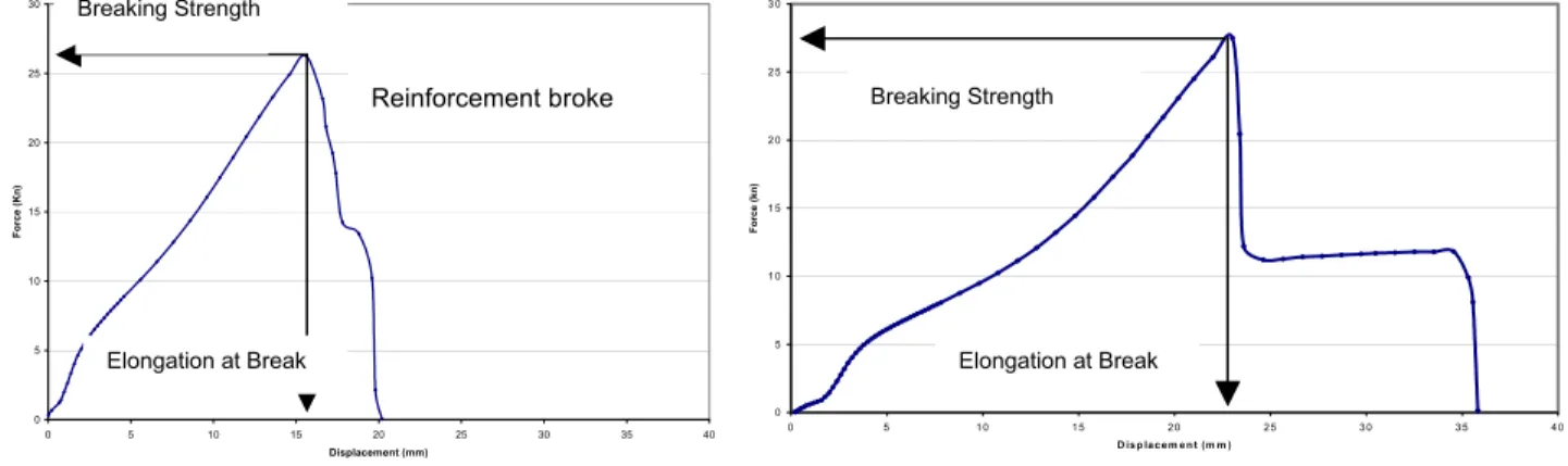
Typical force-displacement curves for the tensile testing of the polyester reinforced roofing membrane are displayed in Figure 1. The load increased with displacement almost linearly at the beginning as the specimen stretched until the reinforcement broke, which caused an abrupt drop in load. No delamination was observed between the polyester fibre and the PVC matrix.
The tensile properties of the polyester reinforced roofing membrane samples are summarized in Table 4. None of the samples met the minimum breaking strength requirement (35 kN/m) as stated in ASTM D4434 [1] except Samples 13A in the cross direction. The samples retained 70-90% of the minimum breaking strength required for new membranes as specified in ASTM D4434 [1] and over 60% of the samples retained more than 80% of that requirement. However, all samples exceeded the minimum elongation at break value (15%) specified by ASTM D4434 [1]. Note at the time the membrane was made for most of these projects the ASTM Standard did not exist.
Figure 1 Typical Force displacement curve for tensile test of polyester reinforced roof
membrane (Sample 21C) in the machine (MD) and cross directions (CD)
Machine Direction Cross Machine Direction Glass Reinforced Samples (ASTM Type II, Grade 1)
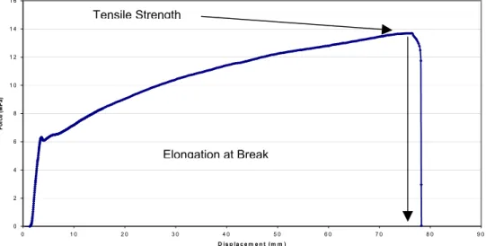
Figure 2 shows a typical force-displacement curve for the tensile testing of the fibreglass reinforced roofing membranes. The load increased linearly with displacement at the beginning. The specimen then started to yield and neck as indicated by the change in slope in the force-displacement curve. It stretched to a high degree (over 100% in general) and finally broke with a snap. No delamination was observed between the fibreglass reinforcement and the PVC matrix.
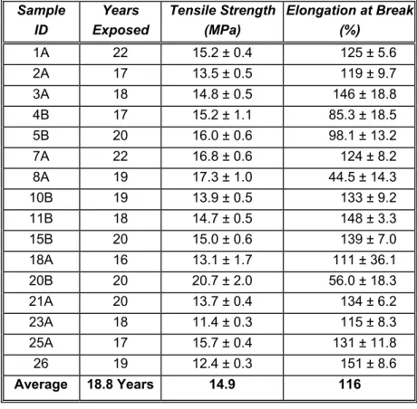
The tensile properties of the fibreglass reinforced roofing membranes are shown in Table 5. All samples exceeded the minimum requirement (10.4 MPa) but did not meet the minimum elongation at break value (250%) as specified by ASTM D4434 [1]. The elongation at break for the samples ranged from 45-150%, which corresponded to 18-60% of the minimum value specified for new membranes in ASTM D4434 [1]. Samples 4B, 5B, 8A, and 20B had significantly lower elongation at break values (18-40% of ASTM minimum) than the rest (44-60% of ASTM minimum).
Linear Dimensional Change
The samples were cut making two specimens of 250 mm X 250 mm (10 in. X 10 in.) using a utility knife with the aid of a plastic template. The material adhered on the G-designated samples was removed by either peeling slowly by hand or scraping carefully using a brass putty knife. Care was taken during the material removal to minimize any damage to the samples. For this test, sample 21A was not evaluated due to limited materials.
0 5 10 15 20 25 30 0 5 10 15 20 25 30 35 40 Displacement (mm) Force (Kn) 0 5 1 0 1 5 2 0 2 5 3 0 0 5 1 0 1 5 2 0 2 5 3 0 3 5 4 0 D is p la c e m e n t (m m ) For ce ( k n) Elongation at Break Reinforcement broke Breaking Strength Breaking Strength Elongation at Break
Figure 2 Typical Force displacement curve tensile test for fibreglass reinforced roofing
membrane Sample 18A).
Table 4 Tensile strength and elongation at break properties of polyester reinforced roofing
membranes (ASTM Type III) with single standard deviation
Breaking Strength (kN/m) Elongation at Break (%) Sample ID Years Exposed MD CD MD CD 1D 22 27.0 ± 3.5 26.0 ± 2.5 22.2 ± 1.8 28.0 ± 3.7 2D 17 25.2 ± 2.1 26.3 ± 2.3 22.7 ± 1.7 27.8 ± 2.4 5C 20 30.2 ± 2.0 31.6 ± 1.4 19.0 ± 2.3 27.5 ± 1.04 6A 17 28.4 ± 0.9 30.0 ± 2.0 27.7 ± 0.6 21.4 ± 1.2 9B 18 26.8 ± 3.2 29.0 ± 1.6 25.1 ± 1.6 19.1 ± 1.9 12A 15 28.3 ± 1.7 28.7 ± 0.7 20.4 ± 1.5 18.7 ± 1.5 13A 19 29.2 ± 2.6 35.0 ± 1.4 28.1 ± 2.4 22.1 ± 1.3 14A 16 24.0 ± 2.4 25.9 ± 3.6 22.6 ± 1.7 17.3 ± 1.8 15D 20 26.6 ± 1.3 27.8 ± 1.7 25.1 ± 0.7 31.7 ± 1.7 16A 17 29.3 ± 3.3 29.6 ± 1.7 21.1 ± 2.3 29.4 ± 1.4 17B 15 26.5 ± 1.3 26.7 ± 1.4 23.3 ± 0.5 26.4 ± 3.7 18C 16 29.6 ± 1.4 26.0 ± 0.06 21.9 ± 3.2 36.8 ± 1.1 19A 19 29.2 ± 2.4 29.4 ± 1.6 23.3 ± 1.9 23.3 ± 1.9 21C 20 30.2 ± 1.9 30.2 ± 1.9 23.4 ± 1.6 22.5 ± 0.9 22A 17 29.0 ± 1.9 31.7 ± 0.8 22.0 ± 2.8 20.0 ± 1.4 Average 19 Years 28.0 28.9 21.7% 24.8% ASTM D4434 [1] 35 35 15.0% 15% Notes: 1. ASTM D4434 [1] approved in 1985
2. 11 projects installed before the standard even existed
3. Changes in scrim have occurred since introduction of the standard
0 2 4 6 8 1 0 1 2 1 4 1 6 0 1 0 2 0 3 0 4 0 5 0 6 0 7 0 8 0 9 0 D is p la c e m e n t ( m m ) For ce ( M Pa) Elongation at Break Tensile Strength
The samples were tested according to ASTM D1204 [6] as specified by ASTM D4434 [1]. Two specimens of dimensions 250 mm x 250 mm (10 in. x 10 in.) were cut from each sample. Before conditioning, each specimen was marked and measured at the midpoint in both the machine and cross machine directions. The specimens were measured using a 450 mm Mitutoyo vernier caliper that has an accuracy of 0.01 mm (0.0005 in.). The specimens were dusted with talc and placed between two pieces of Teflon™ coated paper, which were secured together with paper clips. The assemblies were placed in a convection oven at 80±1°C for 6h. They were then removed from the oven and conditioned at 23±2°°C, 50% relative humidity for at least 1 hour before the final measurements were made. The linear dimensional change is the change in dimension as a percent of the original dimension:
Linear dimensional change = [(Df - Do)/DO] x 100%
Table 5 Tensile strength and percent elongation properties of fibreglass reinforced PVC
roofing membranes (ASTM Type II Grade 1) with single standard deviation
Sample Years Tensile Strength Elongation at Break
ID Exposed (MPa) (%) 1A 22 15.2 ± 0.4 125 ± 5.6 2A 17 13.5 ± 0.5 119 ± 9.7 3A 18 14.8 ± 0.5 146 ± 18.8 4B 17 15.2 ± 1.1 85.3 ± 18.5 5B 20 16.0 ± 0.6 98.1 ± 13.2 7A 22 16.8 ± 0.6 124 ± 8.2 8A 19 17.3 ± 1.0 44.5 ± 14.3 10B 19 13.9 ± 0.5 133 ± 9.2 11B 18 14.7 ± 0.5 148 ± 3.3 15B 20 15.0 ± 0.6 139 ± 7.0 18A 16 13.1 ± 1.7 111 ± 36.1 20B 20 20.7 ± 2.0 56.0 ± 18.3 21A 20 13.7 ± 0.4 134 ± 6.2 23A 18 11.4 ± 0.3 115 ± 8.3 25A 17 15.7 ± 0.4 131 ± 11.8 26 19 12.4 ± 0.3 151 ± 8.6 Average 18.8 Years 14.9 116 Notes: 1. ASTM D4434 [1] approved in 1985
2. 14 projects installed before the standard even existed 3. Elongation affected by adhesive and preparation of sample 4. Still over 100% elongation after 18+ years
Where Df is the final length (or width) of the specimen after the test and DO is the initial length
(or width) of the specimen. A positive linear dimensional change indicates expansion while a negative value denotes shrinkage.
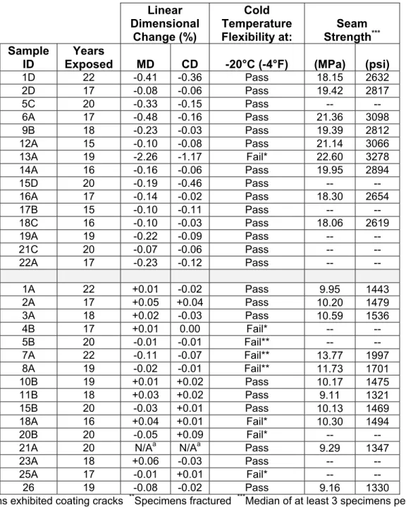
The results of the linear dimensional change of the samples after conditioning at 80 ± 1°C for 6h in a convection oven are shown in Table 6. All polyester reinforced roofing membranes except Sample 13A met the linear dimensional change requirement of 0.5% as stated in ASTM D4434 [1]. All the fibreglass reinforced samples met the linear dimensional change requirement of 0.1% as stated in ASTM D4434 [1].
Table 6 Linear dimensional change, cold temperature flexibility and seam strength Linear Dimensional Change (%) Cold Temperature Flexibility at: Seam Strength*** Sample ID Years
Exposed MD CD -20°C (-4°F) (MPa) (psi)
1D 22 -0.41 -0.36 Pass 18.15 2632 2D 17 -0.08 -0.06 Pass 19.42 2817 5C 20 -0.33 -0.15 Pass -- -- 6A 17 -0.48 -0.16 Pass 21.36 3098 9B 18 -0.23 -0.03 Pass 19.39 2812 12A 15 -0.10 -0.08 Pass 21.14 3066 13A 19 -2.26 -1.17 Fail* 22.60 3278 14A 16 -0.16 -0.06 Pass 19.95 2894 15D 20 -0.19 -0.46 Pass -- -- 16A 17 -0.14 -0.02 Pass 18.30 2654 17B 15 -0.10 -0.11 Pass -- -- 18C 16 -0.10 -0.03 Pass 18.06 2619 19A 19 -0.22 -0.09 Pass -- -- 21C 20 -0.07 -0.06 Pass -- -- 22A 17 -0.23 -0.12 Pass -- -- 1A 22 +0.01 -0.02 Pass 9.95 1443 2A 17 +0.05 +0.04 Pass 10.20 1479 3A 18 +0.02 -0.03 Pass 10.59 1536 4B 17 +0.01 0.00 Fail* -- -- 5B 20 -0.01 -0.01 Fail** -- -- 7A 22 -0.11 -0.07 Fail** 13.77 1997 8A 19 -0.02 -0.01 Fail** 11.73 1701 10B 19 +0.01 +0.02 Pass 10.17 1475 11B 18 +0.03 +0.02 Pass 9.11 1321 15B 20 -0.03 +0.01 Pass 10.13 1469 18A 16 +0.04 +0.01 Fail* 10.30 1494 20B 20 -0.05 +0.09 Fail* -- --
21A 20 N/Aa N/Aa Pass 9.29 1347
23A 18 +0.06 -0.03 Pass -- --
25A 17 -0.01 +0.01 Fail* -- --
26 19 -0.08 -0.02 Pass 9.16 1330
*
Specimens exhibited coating cracks **Specimens fractured ***Median of at least 3 specimens per sample
Low Temperature Flexibility
The samples were cut into specimens of 25 mm X 100 mm (1 in. X 4 in.) using autility knife with
the aid of a plastic template. The material adhered on the G-designated samples was removed by either peeling slowly by hand or scraping carefully using a brass putty knife. Care was taken during the material removal to minimize any damage to the samples.
The samples were tested according to ASTM D2136 [7] at -20°C. The specimens were sandwiched between two glass plates in a freezer at -20°C for 4 hours. They were then removed from the glass plates one at a time and placed inside the environmental chamber, which housed the bending apparatus (Figures 1 and 2). The specimens were placed into the bending apparatus and allowed to equilibrate in the chamber for one minute. When the trigger
pin was released, the flexing plate made a free fall, which bent the specimen. A minimum of three specimens per sample were tested.
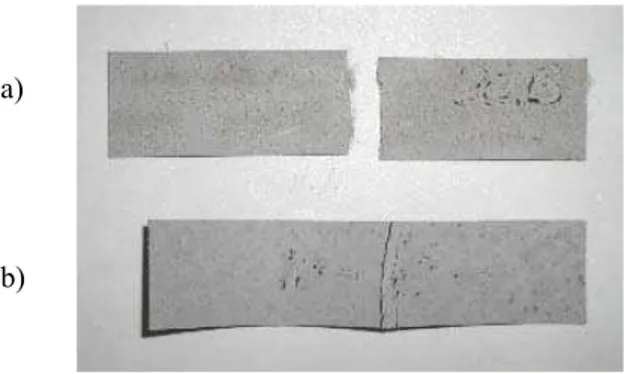
After three specimens had been tested, they were removed from the environmental chamber and examined for surface cracks using a 5X-magnifying glass. During the inspection, each specimen was folded 180° in the same direction as the specimen was bent during the test. If all three specimens showed no cracks in the coating and no fractures, then the sample was considered to have passed. If all three specimens displayed cracks or fracture, the sample failed. However, if only one or two specimens showed cracks, three additional specimens were tested. If any of these exhibited coating cracks or fractures, then the material failed; otherwise, it passed. Typical failed and passed specimens are shown in Figures 3 and 4, respectively.
The results of the cold temperature flexibility test conducted at -20oC (-4ºF) are shown in Table
6. All samples passed except 13A, 4B, 5B, 7A, 8A, 18A, 20B and 25A.
Bending Apparatus Trigger Pin Specimen Cold Chamber Environmental Chamber Specimen Bending Apparatus
Test specimens placed in the bending apparatus were allowed to equilibrate in the environmental chamber
Figure 3 Typical failed specimens showing (a) fracture, (b) surface crack
Figure 4 Typical passed specimens
Seam Strength
The seam strength of the reinforced PVC roofing membrane samples was measured according to ASTM D5868 [8] in a lap shear configuration. The samples were cut into specimens of 50 mm X 200 mm (2 in. X 8 in.), using a utility knife with the aid of a plastic template. The specimens were tested in an Instron machine (model 4502) at a constant crosshead speed of 13 mm/min (0.5 in./min). The distance between the grip and the edge of the seam was 27 mm (1 1/16 in.). Two pieces of sand paper (number 100) were placed between the grips and the specimen to prevent slippage. A minimum of three specimens were tested for each sample. The seam strength of each specimen was calculated by dividing the maximum tensile load by the original cross-sectional area of the specimen (i.e., width X thickness). The seam strength of the reinforced PVC roofing membrane samples was reported as the median of at least 3 specimens and is summarized in Table 6. The seam strength of the glass reinforced membrane samples ranged from 9 to 14 MPa (1300 to 2030 psi) and that of the polyester reinforced membrane samples ranged from 18 to 23 MPa (2610 to 3340 psi).
Typical force-displacement curves for the seam test of the glass and polyester reinforced
roofing membrane samples are displayed in Figure 5.
The load increased with displacement as
the specimen stretched. The slope of the curve then decreased slightly as the stretched zone started to neck and the surrounding material was drawn into this zone. The membrane stretched further and finally broke, which caused an abrupt drop in load. Both the glass and the polyester reinforced PVC membranes failed in similar manner. However, the glass samples stretched and necked to a higher extent because the random short glass fibres moved more freely with the PVC matrix.
(a)
The failure of all specimens occurred in the membrane outside the seam area with the seam remained intact (Figure 6). This indicated that the seam did not deteriorate after the membranes had been in-service for various periods of time and that the seam strength was governed by the tensile strength of the membrane.
Figure 5
Conclusions
Overall, the field performance of these fibreglass and polyester reinforced vinyl membranes, which were analyzed, and found to be without problem. The roofing systems averaging 19 years of age were performing well and without leakage. All membranes were capable of being welded to even after 19 years of weathering.
The laboratory testing confirms that although the products tested lost some of their initial physical properties (as expected), they generally held up well compared to the standard minimum values for testing new PVC roofing membranes according to ASTM D4434 [1]. It is
0.0 0.2 0.4 0.6 0.8 1.0 1.2 1.4 0 20 40 60 80 100 Displacement (mm) Force (kN) Polyester Reinforced Glass Reinforced PVC
Maximum Tensile Load
Seam area Lower grip Upper grip Sand Specimen Typical force-displacement curves for the seam test of the reinforced PVC roofing
important to note, however, that some of these membranes, which had been tested in the NRC laboratory about 15 years ago, exceeded the minimum requirements of the ASTM D4434 [1]. This is an interesting point because as materials age/weather, their properties are expected to degrade.
(a) (b)
Figure 6 Typical failed glass and polyester reinforced seam test specimens (a) failure occurred in the membrane outside the seam area whilethe seam remained intact (b) close up at area of failure.
No prediction can be made as to how long these roof systems will last. But roofs have been in place for 40 years in Europe and this data would indicate that a properly formulated, properly maintained, reinforced PVC roof membrane system could perform in excess of 20-30 years in various climates throughout the Continental U.S. and parts of Canada. Obviously, the exact climate conditions could affect the overall longevity. [9]
Additional testing, such as wind uplift testing, fire testing and hail impact testing would be worthwhile but was not part of this test program.
Recognition
We would like to thank the following roofing consultants/engineers that helped with site visits and test sampling:
Tom Walczak, Principal, Roof Management Consultants, Hopedale, MA 01747; Mike Flaherty, Project Manager, Gale Associates, Weymouth, MA 02189; Dan McLaughlin, Manager, Edwards & Kelcey, Boston, MA 02210; Werner Gumpertz, Simpson, Gumpertz & Heger, Waltham, MA 02453; Ralph Noblin, Noblin & Associates, Bridgewater, MA 02324; Matthew Hoffman, P.E., Principal Engineer, Engineering Diagnostics, Houston, TX 77081; Walter Scarborough, Harwood K. Smith & Partners, Dallas, TX 75201; James Wharry, Wharry Engineering, Dallas, TX 75355; Tesfamarian Merid, D7 Consulting, Newport Beach, CA 92660; Roger Sketch, Roofing Services, PSI, Corona, CA 91720; Dick Wamsat, Allana-Lippert, Palo Alto, CA 94303; Karem Allana, Allana-Lippert, Palo Alto, CA 94303; Chris Nelson, TRS, Martinez, CA 94553
References
2. R.M. Paroli, T.L. Smith, B. Whelan, “Shattering of Unreinforced PVC Roof Membranes: Problem Phenomenon, Causes and Prevention”, NRCA/NIST Tenth Conference on
Roofing Technology, (Gaithersburg, MD, April 22-23, 1993), pp. (1993).
3. F.J. Foley, J.D. Koontz, J.K. Valaltis, “Aging and Hail Research of PVC Membranes”,
12th International Roofing and Waterproofing Conference "Exploring Tomorrow’s
Technology Today", (Orlando, FL, Sept. 25-27, 2002), pp. 1-25 (2002) 4. D638-01 Standard Test Method for Tensile Properties of Plastics 5. D751-00 Standard Test Methods for Coated Fabrics
6. D1204-94 Standard Test Method for Linear Dimensional Changes of Nonrigid Thermoplastic Sheeting or Film at Elevated Temperature
7. D2136-94 Standard Test Method for Coated Fabrics – Low Temperature Bend Test 8. ASTM D5868-95 Lay Shear Adhesion for Fiber Reinforced Plastic (FRP) Bonding
9. H.R. Beer, “Field Study and Laboratory Testing of PVC Roofing Membranes After up to 34 Years Exposure”, ICBEST Sydney, Australia March 2004 – in press.