Calculation of Wind Borne Debris Impact in
Tornado Event
by
Selam Mulugeta Gebru
B.C.E., Auburn University (2008)
Submitted to the Department of Civil and Environmental Engineering
in partial fulfillment of the requirements for the degree of
MASTER OF ENGINEERING IN CIVIL AND ENVIRONMENTAL
ENGINEERING
at the
MASSACHUSETTS INSTITUTE OF TECHNOLOGY
June 2017
@Selam
Gebru 2017. All rights reserved.
The author hereby grants to MIT permission to reproduce and to
distribute publicly paper and electronic copies of this thesis document
in whole or in part in any medium now known or hereafter created.
Autor...Signature
red acted
Author..
. .. ...
..
Department of Civil and Environmental Engineering
Certified by. ..
Signature red acted
May 19, 2017
Certifie by. ...
...
. . ...
Gordana Herning
Postdoctoral Lecturer of Civil and Envir ment I Engineering
SVis
Supervisor
Certified
by...
Signature redacted
...
/ John Ochsendorf
Class of 1942 Professor of Civil and Environmental Engineering and
Architecture
Signature redacted
Thesis
Supervisor
A ccepted by
...
...M HUSS INSTIUTE
Jesse Kroll
OF TECHNOLOGY
Professor
of Civil and Environmental Engineering
JUN
1
4 2017
Chair, Graduate Program Committee
Calculation of Wind Borne Debris Impact in Tornado Event
by
Selam Mulugeta Gebru
Submitted to the Department of Civil and Environmental Engineering on May 19, 2017, in partial fulfillment of the
requirements for the degree of
MASTER OF ENGINEERING IN CIVIL AND ENVIRONMENTAL ENGINEERING
Abstract
In strong wind events like tornado and hurricane, significant destruction is caused to buildings due to wind-borne debris, which are usually damaged structural mem-bers and components with insufficient attachment. This debris, also referred to as missiles, can penetrate building walls and roofs and jeopardize human life. Because of this, there are standard impact criteria provided by Federal Emergency Management Agency (FEMA-P-320, 2014; FEMA-P-361, 2015) and International Code Council (ICC-500, 2014) that need to be met when designing safe rooms or storm shelters. The national wind institute at Texas Tech University has done extensive impact test-ing on different types of structural and non-structural components, which are the basis for current design guidelines.
This thesis focuses on investigating previously developed methods for evaluating the perforation of concrete and steel targets and selecting the most relevant formulas that can be applied for the design of tornado safe rooms. For cast-in-place(CIP) concrete, precast concrete and concrete masonry units (CMU), the best method to estimate perforation limit is the Central Research Institute of the Electric Power Industry (CRIEPI) Formula. For Steel target, both the Ballistic Research Laboratory (BRL) Formula and the Stanford Research Institute (SRI) give useful estimate for perforation limit. These selected concrete and steel target perforation limit formulas can be used for preliminary design of buildings, to withstand the required impact criteria, giving engineers the flexibility to design structures without depending only on using structural components that have been tested to meet the FEMA criteria . Thesis Supervisor: Gordana Herning
Title: Postdoctoral Lecturer of Civil and Environmental Engineering Thesis Supervisor: John Ochsendorf
Title: Class of 1942 Professor of Civil and Environmental Engineering and Architec-ture
Acknowledgments
First and foremost, I want to thank God for his grace and blessings in my life. I would like to thank my thesis advisor Gordana Herning for her incredible insight and direction. It has been a great experience getting to learn from her. I would also like to thank John Ochsendorf for his advice throughout the year.
I would like to thank my parents for their love and guidance all my life. I wouldn't be here without all their sacrifice and support. I would also like to thank my sister for setting the example of working hard to achieve your goals and my brother for believing in me.
I also want to thank everyone at Weatherford & Associates, inc. for mentoring and teaching me for the past ten years.
Finally, I want to say to thank you to the MEng crew for an amazing 9 months together.
Contents
1 Introduction
13
2 Background
15
2.1 Tornadoes . . . . 15
2.2 Safe Room Vs. Storm Shelter . . . . 18
2.3 Current Design practice . . . . 19
3 Motivation
21
4 Literature Review
23
4.1 Current Status of Research . . . . 234.2 Calculating for Perforation and Penetration . . . . 24
4.2.1 Concrete Target . . . . 24
4.2.2 Steel Target . . . . 31
4.3 Experimental Testing of Building Materials for Tornado Events . . . 32
5 Analysis
35
5.1 Selecting Applicable Methods . . . . 355.2 Concrete Target . . . .. . . . 36
5.3 Steel Target . . . . 40
5.4 Tested Construction Materials . . . . 41
6 Results
43
6.1 Concrete Target . . . . 436.1.1 Cast-in-Place/ Precast Concrete . . . . 44
6.1.2 Concrete Masonry Units (CMU) . . . . 46
6.2 Steel Target . . . . 48 6.3 A pplication . . . . 49 6.3.1 Design Example . . . . 50 7 Conclusions 55 A Notation 63 B MatLaB Code 65 C Design Example - LRFD 75
List of Figures
2-1 Tornado . . . . 16
2-2 Recorded EF3, EF4 EF5 level tornadoes in the US . . . . 17
2-3 W ind Zones . . . . 18
3-1 April 2011 tornado occurrences . . . . 22
4-1 Penetration depth for missile entering concrete target (sketch by author) 25 4-2 Perforation limit for missile passing through concrete (sketch by author) 25 6-1 Existing building . . . . 51
6-2 Existing wall . . . . 51
List of Tables
2.1 EF-Scale wind speeds . . . . 16
5.1 Analysis of Concrete Target . . . . 38
5.2 Analysis of Steel Target . . . . 40
5.3 Experimentally Tested Materials by TTU . . . . 41
6.1 Results for CIP or Precast Concrete . . . . 45
6.2 Results for Concrete Masonry Units . . . . 47
6.3 Results for Steel . . . . 48
Chapter 1
Introduction
Wind storm events such as tornadoes and hurricanes are responsible for avoidable loss of human life and significant damage of building structures. One type of damage is perforation of exterior structural elements such as the roof, windows or walls due to the impact of flying debris. These holes cause the wind pressure acting on the inside of the building to increase to a level that is significantly higher than the pressure for which the building was designed. This increase in wind pressure, combined with reduced structural integrity, may lead to local failure, and in severe cases to failure of the structure. Therefore, it is important to design building components that can resist flying debris due to tornado-level winds. The current design guidelines for this condition is based on experimental testing of building assemblies that are subjected to the required high wind speeds and the impacts of wind-borne debris. The components that meet the required criteria are used. This thesis evaluates current methods for estimating perforation of concrete and steel targets to identify ones that can be applied for tornadoes.
Chapter 2 discusses general background on tornadoes as well as current US based design method of tornado-safe rooms using Federal Emergency Management Agency (FEMA) and International Code Council (ICC) guidelines (FEMA-P-361, 2015; ICC-500, 2014).
Chapter 3 discusses the motivation for this thesis topic of tornado-resilient design in general and the specific concentration on evaluating flying debris.
Chapter 4 discusses research that has been done in related engineering disciplines such as for military application and review of currently available approaches for eval-uating concrete and steel penetration thickness and perforation limits. In addition, an overview of experimental testing that serves as the basis for the FEMA criteria is presented (TTU, 2017).
Chapter 5 discusses the methodology for evaluating both concrete and steel targets as well as presenting values for experimentally tested materials.
Chapter 6 discusses results produced for concrete targets, cast-in-place & concrete masonry units, and steel targets using selected methods from chapter 5. It also works through a design example for steel plate shear wall.
Chapter 7 discusses conclusion of the thesis and suggests work for the future of the topic.
Chapter 2
Background
2.1
Tornadoes
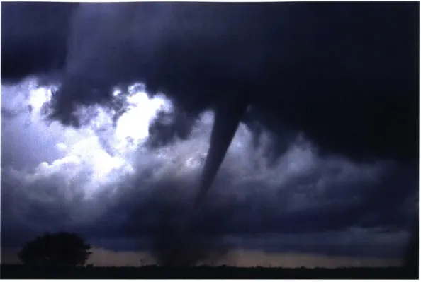
A tornado is one of the most destructive types of storms that occurs due to a violently rotating column of air descending from a thunderstorm touching the ground (See Figure 2-1). Tornado originates from super cell thunderstorms formed in the setting of strong vertical change in wind speed or direction due to height. It has a wind speed considerably higher than the typical design values that are recommended by the design code. It usually only lasts a few minutes but can cause immense destruction and fatalities. It can sometimes travel for hours carrying soil, vegetation and debris and create up to a mile-wide damage path. It eventually starts to die down, decreasing in size and strength. The size of a tornado does not necessarily reflect its strength, since even smaller intensity storms can be responsible for great damage. Even though the average warning time before a tornado touches down is 13 minutes, sometimes there is no time for people to reach a' safe place (NOAA, 2011a). Its visibility depends on the storm system associated with it. When there are clouds or rain surrounding it, the funnel is hard to see, and the debris it picks up can indicate its path.
The intensity of a tornado is classified using the Enhanced Fujita Scale (EF Scale), which assigns wind speed rating to a tornado. It is based on the original Fujita
Figure 2-1: Tornado
Source: Public Domain - Daphne Zaras
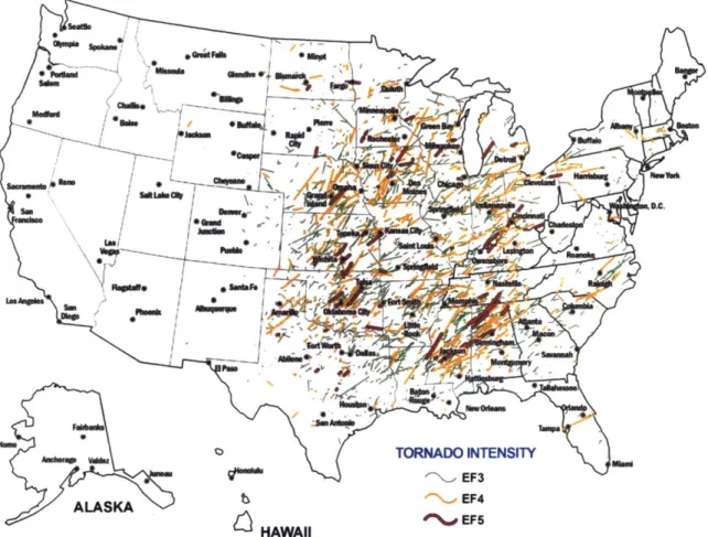
account damage indicators which may have been responsible for over-estimation of wind speeds. The EF scale considers indicators such as building types, structures and trees to give a more accurate estimate of the damage related to the storm intensity. EF-4 and EF-5 tornadoes are categorized as violent and have wind speed higher than 166 mph, as seen in Table 2.1 and Figure 2-2 (NOAA, 2010).
Table 2.1: EF-Scale wind speeds Source: NOAA (2010)
EF-Scale Wind Speed (MPH) Description
EFO 65-85 Gale EF1 86-110 Moderate EF2 11-135 Significant EF3 136-165 Severe EF4 166-200 Devastating EF5 >200 Incredible
Ssdhr
cA"Fd'
0bee Gkd auN-. ALASKAK HAWAII EF4 EF5Figure 2-2: Recorded EF3, EF4 EF5 level tornadoes in the US Source: FEMA-P-320 (2014)
Most US states are at some risk of a tornado impact; however, the central part of the country, also known as the Tornado Alley, experiences the largest number of tornadoes in the world during its peak season between April and June (NOAA, 2010). As seen in Figure 2-3, the United States is dived into four zones based on the data that has been collected on the intensity of tornadoes over the past 60 years. Zone I covers the West Coast, while Zone II covers the North East and the planes east of the Rocky Mountains. Both Zone I and II cover areas with the least tornado activity. Zone III, which covers the coastal areas in the South East, has a higher number of tornadoes. Tornado Alley is in Zone IV and is known for the highest number and intensity of tornadoes in US.
WIND ZONES IN THE UNITED STATES*
ZONZONE I
, MissM ZONE I
swern~~
~
~ ~~
Fargo811"111 Bnv:* DukghI x:
r (Z N nIIIp PZONE e ZONE IVRochesteF Z esufka
SSxe cty (2014)
r e r e ChAm e Des cicago n Cleve wh e
(FEA--30, 01).Sce h af om einoeomedton"r*bsdo
sn2z -~,. - sp naC,
relte intsiZtinE wth storm b
romoranenise bidnsgn
ed
ae nth rtra oulne n h gielnStor sheler
s
siia to amf rooma
buFt is deine ccrinNEhIntra
-- 1 F4 _Kansas Cy
P~~~~~ ZONEjo )-fZOE1
:::::~~Tl" E i NnhR^"wRTileZO
Figre 2:IndZe
2.2 Safem Forts.Str Shelter
person n s trctreha a very higahike.ihit d ZON sIIIlinatrad vn
relaed ithstom inenstie tht Fwr porth o l reored Sferom anbeon roo , o anentrebuidin, dsigebased on thecriei oulndi h-dln
(FEMA--361,2Pog)
tional Code Council (ICC-500, 2014). Safe rooms are designed more conservatively than storm shelters since FEMA-P-361 (2015) includes all criteria listed on ICC-500 (2014) but has additional provisions with respect to flood hazards and the horizontal missile impact speed, which are used in for hurricane-resistant design of buildings. Both codes aim to provide a building that is significantly stronger than if it was designed based on the requirements of only the International Building Code (IBC, 2009) where the design wind speed in IBC (2009) is lower than both FEMA-P-361 (2015) & ICC-500 (2014) speeds and there is no impact deign criteria required by IBC (2009).
2.3
Current Design practice
Currently there are two steps in designing safe rooms or storm shelters according to FEMA-P-361 (2015) or ICC-500 (2014), respectively. The first step is designing the building for wind pressure similar to any wind design but for a much higher speed, that may reach up to 250 mph. To compare the requirements from FEMA-P-361 (2015) and the IBC (2009), the latter has a minimum requirement that reaches only up to 150 mph, making wind forces acting on safe rooms around 8 times higher than those in a standard building located in wind zone 4, where the FEMA-P-361 (2015) design wind speed is 250 mph, while the IBC (2009) design wind speed is only 90
mph.
The second step of the design is testing a structure component (eg. wall or roof sub-assembly) for resistance to wind-borne debris according to the criteria set by FEMA or ICC. The tornado missile testing for both FEMA-P-361 (2015) and ICC-500 (2014) uses 15 pound 2x4 inch framing specimen impacting the target at a test speed of 80-100mph vertically. The missile impacts the target at 2/3 of this speed horizontally. Researchers at the Debris Impact Facility of the National Wind Institute at Texas Tech University have tested various structural and non structural components, such as wall assemblies, roof assemblies, doors and windows. The results are the basis for current design guidelines (FEMA-P-361, 2015; ICC-500, 2014) for safe rooms or
storm shelters.
Chapter 3
Motivation
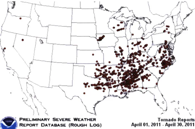
April 2011 was a historic time for tornadoes in United States. Some of the most destructive and deadliest tornado events have occurred, and the super outbreak of wind storms was responsible for the death of 369 people, tens of thousands of injuries, and a total damage cost surpassing 2 billion dollars (NOAA, 2011b).
There were 6 different sets of outbreaks with the worst one occurring between April 25th-28th when 305 tornadoes were estimated to have occurred, with 190 funnel clouds touching down between the 27th and 28th of April. Out of these 190 tornadoes, approximately 25% were at and above high intensity on the Enhanced Fujita (EF) Scale (NOAA, 2011b). Three tornadoes were EF-5, twelve were EF-4, and twenty were EF-3 and together they were responsible for the death of nearly 350 people, mostly in Alabama. The greatest damage occurred due to the 1.5 mile-wide EF-4 tornado that travelled on the ground for over 80 miles, at a velocity of 190mph. It ravaged the cities of Tuscaloosa and Birmingham, killing 65 people, with over a thousand injuries, making it the deadliest tornado since the Kansas tornado of May 25, 1955 that killed 80 people (NOAA, 2011b). Figure 3-1 shows the total number of tornadoes that occurred during April 2011.
These devastating events show the importance of a structurally sound shelter with economically feasible designs for new buildings & retrofit of the existing ones. When a tornado hits a built structure, a debris missile can penetrate walls or roof, which will lead to wind pressure entering the structure and pushing on the walls from the
PRELIMINARY SEVERE WEATHER
Tornado Reports
REPORT DATABASE (ROUGH LOG) April 01, 2011 - April 30, 2011
NOAAlStorm Pigdictlon Center Normun. Oiahom. Updated: Saturday April 30. 2011 14:32 CT
Figure 3-1: April 2011 tornado occurrences Source: NOAA (2011b)
inside. As the wind pressure acting on the inside increases, the lateral forces on the walls rise, which may result in failure of the structure. This kind of failure sometimes looks like the building had exploded, which previously has led to the mistaken theory of the need to balance the inside and outside pressures on a building by opening a door or window. However, any opening in the structure will lead to an increase in pressure on the building and therefore it is important to design shelters to have wall and roofs that can withstand damage and perforation from flying debris or missiles
Chapter 4
Literature Review
4.1
Current Status of Research
Research initiated by the U.S. Military is responsible for the majority of present knowledge related to ballistic and missile impact study. This is due to the necessity of having protective structures in military bases and in war zones. Since the early 1900s, the US Army has been conducting studies on the effect of missile impact on concrete and steel structures (Amirikian, 1950). In recent years, research in non-military applications, especially related to hurricanes & malevolent activities aimed at civic infrastructures, has increased (Dorshorst, 2013; Sassa et al., 2009; Antaki, 2009).
A study by Lin et al. (2007) utilized experimental and numerical methods to evaluate the trajectory of wind borne debris in horizontal winds. This study showed that the "ratio of horizontal debris speed to wind gust speed is primarily a function of the horizontal distance traveled by the debris as it accelerates toward the wind speed", which may be valuable to institute a debris impact standard. This research used compact and rod type missiles to represent timber framing and roof gravel.
A numerical model of the trajectory of plates in windstorms was developed by Holmes et al. (2005) and was compared to the results from experimental tests, done in wind tunnels by Tachikawa (1983). The purpose of this research was to have greater understanding of wind borne debris impacts under severe wind conditions.
Holladay (2012) performed an impact test on an aluminum plate and an aluminum mesh double bumper shield and compared the results to the ballistic limit equation that was developed for aluminum monolithic shield by NASA (2009). Holladay (2012) used a Magnetic Rail Gun to fire the missile, which was a rectangular cube weighing
1 gram (0.0022 lbs), at a speed of 280 t 50 m/s (918 t 164 ft/s). For the plate, the experimental result was similar to the calculated value; however, for the mesh it was discovered that the ballistic limit equation gives a conservative result. The mesh design according to the experimental study could lead to material savings of 23%.
National Aeronautics and Space Administration (NASA) research on the impact of orbital debris on spacecraft at very high speeds, which can lead to damage or failure of systems, produced a three-part ballistic limit equation which can be used in the design of spacecraft walls to withstand missile impact under hyper-speed of up to 7 km/s (15,658 mph). Schonberg (2008) discusses these ballistic limit equations and their limits.
4.2
Calculating for Perforation and Penetration
4.2.1
Concrete Target
When studying the effect of missile impact on a concrete structure, there are two main effects that need to be examined: penetration depth and perforation limit.
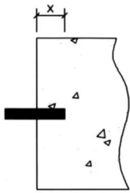
Penetration depth (x) is the depth to which missile enters a massive concrete target without passing through the back of the target, as shown in Figure 4-1 (Li et al., 2005). Three core factors that influence the penetration depth are the physical properties of the missile, such as weight and size, the impact speed of the missile, and the material characteristics of the target (Amirikian, 1950).
Perforation Limit (e) is the thickness of the target through which the missile will pass all the way through the target and come out in the back, as shown on Figure 4-2 (Li et al., 2005). In most methods, the perforation limit is a factor of the penetration depth. Both penetration depth and perforation limit are measured in inches.
4
44
Figure 4-1: Penetration depth for missile entering concrete target (sketch by author)
4
Figure 4-2: Perforation limit for missile passing through concrete (sketch by author)
Other effects are involved in the study of missile impact such as scabbing, which is the expelling of fragments of concrete from the back surface of the target and spalling, which is the expelling of fragments of concrete from the front surface of the target
(Li et al., 2005). However, these two effects are not considered in this thesis.
Below is a list of methods selected for analyzing the penetration depth and per-foration limit.
Modified Petry Formula
Modified Petry Formula is the oldest available expression for penetration depth (x) which was developed in 1910 for military conditions such as impact of bullets and rocket-assisted bombs (Amirikian, 1950). It is based on the equation of motion having a constant instantaneous resisting force and the component drag-resisting force dependent on the square of the impacted velocity (Li et al., 2005). The Modifed Petry
Formula for perforation limit (e) was proposed by Amirikian (1950):
e = 2x (Eq. 4.1)
M
v 2where, X = 12Kp log0 ( 1 + 215000)
M is the weight of the missile in pounds, V is the speed at which the missile impacts the target in ft/s, and d is the missile diameter in inches. The Petry formula also considers the influence of target reinforcement and is represented by the concrete penetrability coefficient K, which is equal to 0.00426 for normal reinforced concrete, 0.00284 for special reinforced concrete and 0.0079 for plane or unreinforced concrete (Li et al., 2005).
Ballistic Research Laboratory (BRL) Formula
The Ballistic Research Laboratory (BRL) formula for penetration depth (x), de-veloped in 1941, originally assumed a compressive strength of the concrete target to be 3000 psi, but was later revised to be applicable to a broader range of targets (Kosteski et al., 2015). The BRL Formula for perforation limit (e) was proposed by Chelapati & Kennedy (1972):
e = 1.3x (Eq. 4.2)
where,
w 427((M
V )'
T
d2 1000f'
is the compressive strength of the target in psi. Parameters M, V, & d are the same as in Eq. 4.1.Army Corps of Engineers (ACE) Formula
The Army Corps of Engineers (ACE) estimated the perforation of concrete based
on the highly documented experimental research done by the US Army and the
Ballis-tic Research Laboratory (Gwaltney, 1968). The experiment was performed on targets
mis-sile at a high velocity, where a 6" diameter cylindrical mismis-sile weighing 100 lbs will have a perforation limit above 3 ft for a missile impact speed of 1000 ft/s (Gwaltney, 1968):
e = 1.23d + 1.07x. (Eq. 4.3)
where, x - d .1
+
0.5d'
~
c- d2 1000Parameters M, V, d are the same as in Eq. 4.1 and
f'
is the same as in Eq. 4.2. There are limits on the applicability of this expression, which are a missile diameter between 1 and 16 inches, missile weight between 0.4 and 2500 pounds, target compressive strength ranging between 1500 to 8000 psi and missile speed ranging between 500 and 3000 ft/s (Gwaltney, 1968).Modified National Defense Research Committee (NDRC) Formula
Based on the ACE formula, the National Defense Research Committee (NDRC) proposed a theory in 1946 stating that, for a small penetration depth, the contact force between the target and projectile increases linearly until it reaches a maximum value. For any combination of values of parameters, this maximum contact force can be assumed to remain constant for small penetration depth (Li et al., 2005). The experiments were done using 0.5 caliber hardened steel missile, striking the target that has thickness between 3 to 18 inches, at an impact velocity ranging between 600 and 2000 ft/s (NDRC, 1946):
X2
e = 3.19x - 0
.
7 1 8- for - < 1.35 (Eq. 4.4a)d d e = 1.32d + 1.24x for 1.35<-x < 13.5 (Eq. 4.4b) d where, x = 2dG-5 for G > 1 x=d(G+1) for G<1 G 180N*M V 1. d J O
1000d
N is the nose shape factor of the missile with values 0.72 for flat nose, 0.84 for hemispherical nose, 1.0 for blunt nose and 1.14 for very sharp nose. Parameters M, V, d are the same as in Eq. 4.1 and
f'
is the same as in Eq. 4.2. Originally, the Modifed NDRC Formula used a concrete penetrability factor (K,) similar values to the Modified Petry formula. In 1966, a replacement Modified NDRC Formula, based on the reciprocal relationship between concrete penetrability coefficient (Kp) and its180
compressive strength (f') in psi, was proposed: k = (Li et al., 2005).
Kar Formula
Kar Formula applied regression analysis to revise the Modified NDRC Formula (Eq. 4.4) to account for the type of missile material and the size of aggregates in the target (Li et al., 2005). When the missile is made of steel, the penetration depth will be the same as that given in the Modified NDRC Formula. However, the perforation limit, e, will still be different from the Modified NDRC Formula since the limit takes the aggregate size into consideration.
x2
e = 3.19x - 0.718-- + a
for
- < 1.35 (Eq. 4.5a)d
d
x e = 1.32d + 1.24x + afor
1.35<- < 13.5 d (Eq. 4.5b) where, x = 2dG0 5 for G>
1x = d(G +1) for G<1
G -180N*M
(E)1.25
( V) 1.8V
1f- Es
J1000d
E8 is the modulus of elasticity of steel in ksi, E is modulus of elasticity of the
missile in ksi, and a is half the aggregate size in the target in inches (Li et al., 2005). Parameters M, V, d are the same as in Eq. 4.1 and
f
is the same as in Eq. 4.2.Hughes Formula
equation to develop the penetration formula based on the assumption that the re-lationship between impact force and penetration depth is parabolic. The main im-provement over the NDRC formula is that Hughes took the brittle nature of concrete failure into consideration.
X
e = 3.6x for -<0.7 (Eq. 4.6a)
d x e 1.58x + 1.4d for - > 0.7 (Eq. 4.6b) d 0. 19dNh Ih where, x -S MV 2 Ih = fld fjd3 S
=
1.0 + 12.3 ln(1.0 + 0.0 3Ih)Ih is the impact factor in terms of the concrete tensile strength (ft) in psi, where and Nh is the nose shape factor of the missile with values 1.0 for flat nose, 1.26 for spherical nose, 1.12 for blunt nose and 1.39 for very sharp nose (Hughes, 1984). Parameters M, V, d are the same as in Eq. 4.1.
Degen Perforation Formula
Degen (1980) proposed a new perforation formula after performing statistical anal-ysis on experimental data from numerous investigations such as the "Study on the penetration of reinforced concrete slabs by rigid missiles" by Goldstein & Berriaud
(1977).
x2
e = 2.2x - 0.3 for - < 1.52 (Eq. 4.7a)
d d
e = 0.69d + 1.29x for 2.65<x < 18 (Eq. 4.7b)
d
where, x - penetration depth from Eq.4.4
Parameter d is the same as in Eq. 4.1. There are limits on the applicability of this formula: the diameter of missile is between 3.94 and 12.20 inches, wall target
thickness is between 5.9 and 24 inches, target compressive strength ranges between 82 to 1020 psi and missile speed ranges between 4119 and 6251 ft/s (Li et al., 2005).
Chang Formula
Chang used homogeneous dimensionless equation to develop semi-analytical for-mulas for perforation of a target impacted with solid steel missiles. The coefficients for this formula were determined using Bayesian statistics which was better fit to the available data than the classical statistical method for estimating limitations (Li et al., 2005).
e = d (Eq. 4.8)
\V
fcd3
where u is a reference velocity equal to 200 ft/s (Li et al., 2005). Parameters M, V, d are the same as in Eq. 4.1 and
f'
is the same as in Eq. 4.2.Adeli and Amin Formula
Adeli & Amin (1985) adapted the impact factor, I,, introduced by Haldar et al. (1983), based on experimental tests conducted in Europe and USA, to illustrate the relationship they observed between the impact factor and penetration depth. They discovered best fit for this relationship to be quadratic and cubic polynomial.
e = 1.8685d + 0.4035dla - 0.0114dja2 for 0.3 < I < 4 (Eq. 4.9)
where, x = 0.0416d
+
0.1698dIa - 0.0045dIa2for
0.3 < I < 4x = 0.0123d + 0.196dIa - 0.008dja2 + 0.0001dIa3 for 4 < I, 21
x = 1.8685d + 0.4035dLa - 0.0114dla2
for
0.3 < I,<
21MNV2
a fId3
The limits on the applicability of this formula are missile diameter less than 11.8 inches, ratio of wall thickness over diameter between 0.7 and 18, ratio penetration depth over diameter ranging between 0.7 to 18, missile weight ranging between 0.24
and 756 pounds and missile velocity between 88.5 and 1023 ft/s (Adeli & Amin, 1985). Parameters M, V, d are the same as in Eq. 4.1 and
f'
is the same as in Eq. 4.2.CRIEPI Formula
The model of the Central Research Institute of the Electric Power Industry (CRIEPI) of Japan proposed a non-dimensional perforation limit to modify the Chang Formula Li et al. (2005).
e = 0.9d( J) (Eq. 4.10)
V/
f'd3
where parameters M, V, d are the same as in Eq. 4.1 and f' is the same as in Eq. 4.2. This formula is applicable for targets with a compressive strength less than 9891 psi Ben-Dor et al. (2013). The CRIEPI Formula was based on experimental testing done using 2.36" diameter missile weighing 4.41b impacting a target with 3911 psi compressive strength at speed ranging between 200-800 ft/sec.
4.2.2
Steel Target
There are two perforation limit formulas for analyzing steel targets, where T is the thickness of the steel target at which the missile will just have perforated it.
Ballistic Research Laboratory (BRL) Formula
The Ballistic Research Laboratory (BRL) perforation limit formula was derived for steel targets based on experiments performed by the Ballistic Research Laboratory using cylindrical projectiles with small diameter and long length, impacting very thin targets (Gwaltney, 1968).
2
MV2
3
T= S672d2d (Eq. 4.11)
where M is weight of the missile in pounds, V is the speed at which the missile impacts the target in ft/s, and d is the missile diameter in inches.
Stanford Research Institute (SRI)
The Stanford formula was derived through experimental data where the target's bilateral tension stress reduces the ultimate tensile strength.Gwaltney (1968)
E_
S
0T2+ Wd 4,000T2
+
1500T,
(Eq. 4.12)where E is critical kinetic energy required for perforation in ft-lb, S is ultimate tensile strength of the steel target in psi, W is the span between rigid supports in inch, W, is standard width equal to 4 inch, M is weight of the missile in pounds, V is the speed at which the missile impacts the target in ft/s, and d is the missile diameter in inches (Gwaltney, 1968). Solving directly for the perforation thickness:
/MV2
(W
2 WT, = 0.045 + 0.0022
-0.047
. (Eq. 4.13)dS
WS
WS
Limits on the applicability of this formula are: a ratio of target thickness to missile diameter between 0.1 and 0.8, ratio of rigid support span to missile diameter between 5 to 8, ratio of rigid support span to perforation thickness between 8 to 100, ratio of missile thickness to missile length between 0.002 to 0.05, ratio of missile length to missile diameter between 10 to 50, and missile velocity ranging between 70 to 400 in ft/s.(Gwaltney, 1968)
4.3
Experimental Testing of Building Materials for
Tornado Events
The National Wind Institute (NWI), the nation's leading wind research institute, was established at Texas Tech University in 2012 to perform research on wind sci-ence, wind energy, wind engineering and wind hazard mitigation in order to offer solutions for wind related problems. One major component of the NWI is a debris impact facility, a laboratory which performs "debris impact tests on storm shelters, shelter components and building materials in order to develop the safest, most
impact-resistant materials to better protect individuals" (TTU, 2017). The pneumatic cannon at the debris impact facility can produce wind speeds over 250 mph which is used to perform missile impact test on construction materials and components in a controlled environment based on the criteria set by FEMA. These tested materials are used by architects and engineers to design a shelter that will remain intact during a storm event (TTU, 2017).
Chapter 5
Analysis
5.1
Selecting Applicable Methods
As discussed in Chapter 4, the formulas described were derived from experimental data obtained in different disciplines, such as blast design for military applications. Therefore, they might not be directly applicable in tornado-resistant design of safe rooms.
The purpose of this thesis is to determine the viability of these currently available methods for predicting penetration depth and perforation limits by performing the analysis using parameters that would produce results relevant for tornado impact on buildings.
For the purpose of this thesis, a failed structural component, slab or wall, is defined as having a thickness less than or equal to the perforation limit.
Each of the formulas are analyzed using missile impact criteria prescribed in FEMA-P-361 (2015), as described in Section 5.2 and 5.3 . Assumptions are made for the compressive strength in concrete targets and for the ultimate tensile strength in steel targets, as shown in Section 5.2 and 5.3.
The perforation values from this analysis are compared with the range of thick-nesses of the building components experimentally tested by Texas Tech University, shown in Table 5.3, and the most relevant formulas are selected. The limits of appli-cability that are associated with each formula are also considered in the selection or
elimination of a formula.
The selected formulas are analyzed for different missile speeds and missile weights to choose the most significant formula for the design of wind-borne debris impact of safe rooms. These formulas give engineers freedom when designing safe rooms, where they will not be dependant on testing building component assemblies to resist missile impact but can analytically design different components thickness as needed for the project.
5.2
Concrete Target
As shown in Chapter 4, majority of the formulas have four common inputs that are related to the missile and the target. These are:
Weight of missile in pounds (M) Diameter of missile in inches (d)
Velocity of missile in foot per second (V)
Compressive strength of concrete in pound per square feet (f'c)
Table 5.1 presents the analysis of the different methods discussed in Chapter 4 for calculating of perforation limit and penetration depth of concrete targets, to determine their correlation and differences. For all the evaluations of these methods, the tornado missile impact criteria as prescribed by FEMA-P-361 (2015) is used for the input values listed below:
M - - - Based on FEMA 2x4 timber framing test missile weighing 15 lbs (FEMA-P-361, 2015)
d - - - Based on the diagonal length of 2x4 timber framing which has a nominal size of 1.5 inches by 3.5 inches. The diagonal length is 3.81 inches.
V --- Based on FEMA criteria for horizontal missile speed which is 100 mph (147 ft/sec) (FEMA-P-361, 2015).
f'
- - - Assumed value of 4000 psi based on the standard compressive strength for a slab or a wall, for all formulas except Modified Petry Formula. For evaluation using Modified Petry Formula (Eq. 4.1), normal reinforced concrete is assumed, where the concrete penetrability coefficient (K,) is equal to 0.00426.For evaluation using Modified NDRC formula (Eq. 4.4), Kar formula (Eq. 4.5), Hughes Formula (Eq. 4.6) and Adel & Amin Formula (Eq. 4.9), the 2x4 timber framing missile has a flat nose shape, where the nose shape factor (N) is 0.72 for Modified NDRC Formula (Eq. 4.4) , Kar Formula (Eq. 4.5) and Adel & Amin Formula (Eq. 4.9) and the nose shape factor (Nh) is 1.0 for Hughes Formula (Eq. 4.6) . The Hughes Formula (Eq. 4.6) calculates the impact factor (Ih) in terms of
the concrete tensile strength
(ft), where
ft
= 7.5/f'C.
As discussed in Chapter 4, Kar Formula (Eq. 4.5) also considers the material property of the missile. For the purpose of this thesis, the missile made of 2x4 Southern Pine grade No. 2 is assumed, where its modulus of elasticity (E) is 1400 ksi (NDS, 2015). The modulus of elasticity for steel (E) is 29,000 ksi (Salmon et al., 2009). Kar Formula (Eq. 4.5) takes the aggregate size of the concrete target into consideration, where an average aggregate size of 3/8 inches is assumed. The parameter 'a' in Kar Formula represents half the aggregate size, which has an assumed value of 0.1875 inches.
The Degen Formula (Eq. 4.10) uses the same penetration depth value as the Modified NDRC Formula (Eq. 4.4).
As discussed in chapter 4, there are limits to the applicability of these formulas. The ACE Formula (Eq. 4.3), Modified NDRC Formula (Eq. 4.4) and Degen Formula (Eq. 4.7) are only applicable for very high missile impact speeds, 500 to 2000 ft/s, 600 to 2000 ft/s and 4119 to 6251 ft/s, respectively. Degen Formula (Eq. 4.7) also has a limit related to the compressive strength concrete target where it's only relevant for a range of 82 to 1020 psi.
Table 5.1 shows all the inputs parameters as well as the calculated perforation limit (e), in inches, using all the different formulas. The new MatLab [Mathworks, Version R2016b] Code shown in Appendix B was created to evaluate all these formulas
Modified BRL
ACE
Modified Kar
Hughes
Degen
Chang
Adell & CRIEPI
Petry
Formula Formula NDRC
Formula Formula Formula Formula Amin
Formula
Formula
Formula
Formula
M 15 15 15 15 15 15 - 15 15 15
d
3.81
3.81
3.81
3.81
3.81
3.81
-3.81
3.81
3.81
V 147 147 147 147 147 147 - 147 147 147K,
0.00426
-
-
-
-
-
--
-
-f - 4000 4000 4000 4000 4000 - 4000 4000 4000
ft'
- - - - - 474 - - --N
-
-
-
0.72
0.72
-
- -0.72
-Nh - - - - - 1.0 - - - -E - - - - 29000 - - - - -E - - - - 1400 - - - - -a - - - - 0.1875 - - - --G
-
-
-
0.0230
0.0005
-
-
-
-
-Ih - - - - -
12.3555
- - --Ia
- - - - - -1.0549
-S - - - - - 4.8781 - - - -u - - - - - - - 200 - 200x
0.0021
0.7118
2.2519
3.8977
3.812
1.8335
3.8977
-
0.8219
-e
0.0044
0.9253
7.0959
9.5708
9.6093
6.6007
7.3788
4.9808
8.6924
4.4827
00 H CD c-fl I, 0 0 ~1 CD CDH
CDusing the parameters discussed above.
When looking at table 5.1, there are three different groups of perforation limit results.
In the first group are Modified Petry Formula and BRL Formula, where the perfo-ration limit is less than 1 inch, which is considerably smaller than the range of thick-nesses of experimentally tested concrete components, performed by TTU as shown on Table 5.3. This is probably due to the fact that both formulas were developed for impact of bullets and bombs, as such assume high missile speed.
In the second group are Modified NDRC Formula, Kar Formula and Adell & Amin Formula, where the perforation limit is higher than 8 inches, surpassing the thickness of all the experimentally tested concrete components shown on Table 5.3. Kar formula and Modified NDRC Formula are related to each other, where Kar Formula is revised from the Modified NDRC Formula, making the similar solution reasonable. The discrepancies between the thickness of the tested components and the calculated perforation limit is due to the limits in the applicability of the Modified NDRC Formula, where it is only relevant for missile speed higher than 600 ft/s. Adell & Amin Formula is applicable for wide range of missile weights and speeds, 0.24-756 lbs and 88.5-1023 ft/s, respectively. However the ratio of the penetration depth over the missile diameter, which is 0.215 is less than the applicable range of 0.7 to 18 making it unsuitable for calculating perforation limit due to tornado missiles.
In the third group are five formulas with perforation limit ranging between 4 to 7 inches, which is close to the range of the experimentally tested components shown on Table 5.3. However, two of the formulas, ACE Formula and Degen Formula, are not applicable since they are only relevant for a high missile speed, above 500 ft/sec and 4119 ft/s respectively. Degen Formula is also limited by its restriction on the target compressive strength (f, ) where it only applies for f, less than 1020 psi. These limits can explain the difference between the calculated perforation limit and the experimentally tested thickness.
This leaves the three relevant formulas, Hughes Formula, Chang Formula and CRIEPI Formula, where there are no limits preventing them from being used to
analyze the peroration of concrete target due to wind-borne missiles in tornado event.
5.3
Steel Target
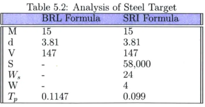
For steel targets, there are only two current methods for analyzing perforation limit (Tp) which are the BRL Formula and SRI Formula, as discussed in chapter 4. As with concrete targets, both methods take into consideration the missile diameter (d) in inches, missile speed (V) in ft/s, and missile weight (M) in pounds. Similar to the analysis of concrete targets, the values for the missile characteristics are based of the FEMA-P-361 (2015) criteria, which are:
M - - - Based on FEMA 2x4 timber framing test missile weighing 15 lbs (FEMA-P-361, 2015)
d - - - Based on the diagonal length of 2x4 timber framing which has a nominal size of 1.5 inches by 3.5 inches. The diagonal length is 3.81 inches. V --- Based on FEMA criteria for horizontal missile speed which is 100 mph (147 ft/sec) (FEMA-P-361, 2015).
In addition to these parameters, the SRI Formula also considers target properties such as ultimate tensile strength (S) of the steel target equal to 58,000 psi for A36 steel and an assumed span between rigid supports (W,) of 24 inch for typical timber house stud spacing (Salmon et al., 2009).
Table 5.2 shows all the inputs as well as the calculated perforation limit (Tp) using the two available formulas, BRL Formula and SRI Formula. The new MatLab [Mathworks, Version R2016b] Code shown in Appendix B was created to evaluate these formulas using the parameters discussed above.
Table 5.2: Analysis of Steel Target
M 15 15 d 3.81 3.81 V 147 147 S - 58,000 W - 24 W -
4
T,
0.1147
0.099
Both BRL Formula and SRI Formula provide calculated values within the range of the experimentally tested components thicknesses provided in Table 5.3. Therefore both formulas are useful and relevant in the design of impact resistant structure from wind-borne debris, in a tornado event.
5.4
Tested Construction Materials
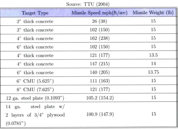
Table 5.3 shows a selection of building components that were tested by the Debris Impact Facility at Texas Tech University TTU (2004). It shows the missile threshold speed above which the concrete and steel targets were perforated.
Table 5.3: Experimentally Tested Materials by TTU Source: TTU (2004)
Target Type Missile Speed mph(ft/sec) Missile Weight (lb)
2" thick concrete 26 (38) 15 3" thick concrete 102 (150) 15 4" thick concrete 162 (238) 15 6" thick concrete 102 (150) 15 4" thick concrete 121 (177) 13.5 4" thick concrete 147 (215) 14 6" thick concrete 140 (205) 13.75 6" CMU (5.625") 111 (163) 15 8" CMU (7.625") 121 (177) 15
12 ga. steel plate (0.1093") 105.2 (154.2) 15
14 ga. steel plate w/
2 layers of 3/4" plywood 100.9 (147.9) 15
Chapter 6
Results
6.1
Concrete Target
Two types of concrete targets are considered in this thesis. The first type is cast-in place (CIP) or precast concrete, wall or slab of any size, cast around the reinforcing steel using a concrete mix with an assumed compressive strength of 4000 psi. The only difference between precast and CIP concrete is the former comes to construction site as a module after the concrete has already set while the later is cast on site. All the formulas discussed in chapter 4 were developed for this type of concrete structure. The second type of concrete target considered in this thesis is Concrete Masonry Units (CMU). CMU walls are constructed from rectangular blocks made from cast concrete. The most common CMU block in the US has two hollow cores, known as cells. Nominal dimensions of an 8 inch CMU unit are 8 inch thickness, 16 inch length and 8 inch height. Vertical reinforcement bars are placed in the cells to strengthen CMU walls. The cells with vertical reinforcement need to be filled with grout so that the rebar can bond with the wall.
The main difference between the properties of CIP/ precast concrete and CMU are due to the compressive strength of the concrete mix. A regular Type M mortar CMU has compressive strength of 1900 psi.
6.1.1
Cast-in-Place/ Precast Concrete
The analysis from chapter 5 was used to select the best methods for evaluating the perforation of concrete targets. As shown in chapter 5, when relating calculated perforation limits to tested materials, Modified Petry Formula and BRL Formula produced perforation values equal 0.0044" and 0.9253", respectively. These are sig-nificantly lower values than the thicknesses of tested concrete walls (2" to 6") as shown in Table 5.3.
On the other side, the values obtained from Modified NDRC Formula, Kar For-mula, and Adel & Amin Formula were equal to 9.5708", 9.6093" and 8.6924". These values surpass the maximum 6" thickness of concrete tested by TTU (2004). Degen Formula and ACE Formula produced values equal to 7.3788" and 7.0959", respec-tively, which is close to the maximum 6" of concrete thickness tested by TTU. How-ever, they were eliminated from consideration due the limits on their applicability where they are only reliable for missile speed higher than 500 ft/s.
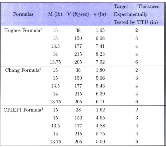
This left three formulas that produced perforation limit between 4 and 6 inches which is within the thickness range of tested walls. These are Hughes, Chang and CRIEPI formulas and the perforation limit values are 6.6007", 4.9808" and 4.4827", respectively. The new MatLab [Mathworks, Version R2016b] Code shown in Appendix B was utilized to evaluate the latter three methods for different missile weights and speeds shown in Table 6.1. Concrete target compressive strength of 4000 psi and missile diameter of 3.81 inches was assumed for all the evaluations.
Table 6.1 shows the calculated perforation limit of CIP or precast concrete target for different missile weights and missile speeds. It also shows the concrete target thicknesses of the experimentally tested components by TTU, for the same missile speed and weight used for calculating the perforation limit.
For a missile speed of 38 ft/s, all three methods determine an estimated perforation limit lower than the tested sizes shown on Table 5.3. However, as the missile speed increases, the formulas overestimate the perforation.
Table 6.1: Results for CIP or Precast Concrete
Target Thickness
Formulas M (lb) V (ft/sec) e (in) Experimentally
Tested by TTU (in)
Hughes Formula' 15 38 1.65 2 15 150 6.68 3 13.5 177 7.41 4 14 215 8.23 4 13.75 205 7.92 6 Chang Formula2 15 38 1.80 2 15 150 5.06 3 13.5 177 5.43 4 14 215 6.39 4 13.75 205 6.11 6 CRIEPI Formula2 15 38 1.62 2 15 150 4.55 3 13.5 177 4.88 4 14 215 5.75 4 13.75 205 5.50 6 1 Hughes (1984), 2 Li et al. (2005)
This is especially true for the Hughes formula which gives a perforation limit of 6.68" and 8.23" at a missile speed of 150 ft/s and 215 ft/s, respectively. These values are double the size of the experimentally tested thicknesses, which are 3" and 4" respectively.
Chang Formula provides a better estimation than Hughes Formula, with perfora-tion limit values of 5.06" and 5.43" for the same missile speeds of 150 ft/s and 215 ft/s, respectively. However, these values are still 70% and 40%, respectively, higher than the experimentally tested thicknesses.
None of the formulas offer estimation that closely aligns with TTU testing param-eters. However, out of the three, the CRIEPI formula has the closest relationship to the tested values with perforation limit values of 4.55" and 4.88" at a missile speed
of 150 ft/s and 215 ft/s, respectively. These values are only 34 % and 18 % higher than the experimentally tested thickness which are 3" and 4" respectively.
The CRIEPI Formula was based on experimental testing done using 2.36" diam-eter missile weighting 4.4 lb impacting a target with 3911 psi compressive strength at speed ranging between 200-800 ft/s. These experiment criterion are the closest to that of the missile testing guidelines set by FEMA-P-361 (2015) for the design of tornadoes.
The 4.4 lb missile weight used in deriving the CRIEPI Formula is less than 15 lb missile weight prescribed by FEMA-P-361 (2015). However, the missile speed has greater influence on the peroration limit than the missile weight. This can be seen by comparing the 4.55" perforation limit calculated for 15 lb missile at a speed of 150 ft/sec with the 5.75" perforation limit calculated for 14 lb missile at a speed of 215 ft/sec. Even thought the missile weight decreased by 7%, the perforation limit increased by 26 % because the missile speed increased by 43%
Therefore, this formula can be used to estimate the thickness of a concrete safe room wall and slabs.
6.1.2
Concrete Masonry Units (CMU)
Concrete masonry units (CMU) are used for construction of walls in most small shelters and as such have to be able to resist the impact of flying debris. Even though none of the formulas were derived for CMU, they can still be applicable because CMU is a concrete cast block, as described in section 6.1. The compressive strength of regular Type M mortar CMU is 1900 psi, which is used for the analysis shown in Table 6.2. Same as for the cast-in-place concrete, a missile diameter of 3.81 inch was used. Table 6.2 lists the calculated perforation limit of CMU target for two different missile speeds. It also shows the concrete target thicknesses of the experimentally tested components by TTU, for the same missile speeds used for calculating the perforation limit. Both of the experimentally tested 6" and 8" CMU walls are reinforced with grout and 4 rebar in every cell.
Table 6.2: Results for Concrete Masonry Units
Target
Thickness
Formulas
M (lb)
V (ft/sec) e (in)
Experimentally
Tested by TTU (in)
Hughes Formula'
15
163
7.9
6" CMU (5.625")
15
177
8.37
8" CMU (7.625")
Chang Formula
215
163
7.8
6" CMU (5.625")
15
177
8.30
8" CMU (7.625")
CRIEPI Formula
215
163
7.0
6" CMU (5.625")
15
177
7.476
8" CMU (7.625")
1
Hughes (1984),
2Li et al. (2005)
Similar to the cast in place concrete, Hughes Formula and Chang Formula
overes-timate the perforation limit for CMU targets when compared to the experimentally
tested thicknesses. However both formulas give a closer estimation for CMU than
for CIP concrete. For a missile speed of 177 ft/s, the perforation limit values
ob-tained from Hughes Formula and Chang Formula are 8.37" and 8.30", respectively.
These values are only 10% and 9%, respectively, higher than the experimentally tested
component which is an 8" CMU wall reinforced with grout and 4 rebar in every cell.
However for the lower missile speed of 163 ft/s, the perforation limit values
ob-tained from Hughes Formula and Chang Formula are 7.9" and 7.8", respectively,
where these values are 40% and 38%, respectively, higher than the experimentally
tested component which is a 6" CMU wall reinforced with grout and 4 rebar in every
cell.
Therefore the CRIEPI Formula is the best estimator out of the three methods.
For the missile speeds 163 ft/s and 177 ft/s, the perforation limit values obtained from
CRIEPI Formula are 7.0" and 7.476", respectively. There is only a difference of 24%
and 2%, respectively, between the calculated perforation limit and the experimentally
tested components, which are 8" CMU wall and 6" CMU wall, respectively, reinforced
with grout and 4 rebar in every cell. .
These calculated perforation limit values also show that each cell of the concrete masonry units has to be filled with grout to full height in order to resist the missile impact since all the calculated values are larger than the face shell thickness of 8" or 6" CMU, which is only between 1-1.5".
6.2
Steel Target
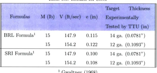
For steel targets, there are only two methods for determining the perforation limit, BRL & SRI, and both were evaluated for assemblies with wall studs spaced at 24 inches and the steel target attached with metal screws at 16 inches spacing. The ultimate tensile strength of the target is assumed to be 58,000 psi. Table 6.3 lists the calculated perforation limit of steel target at two different missile speeds. It also shows the steel target gauge and thicknesses of the experimentally tested components by TTU, for the same missile speeds used for calculating the perforation limit. The 14 ga experimentally tested thickness shown on Table 6.3 is part of a wall assembly that has an additional 2 layers of 3/4" plywood on top the steel target.
Table 6.3: Results for Steel
Target Thickness
Formulas M (lb) V (ft/see) e (in) Experimentally
Tested by TTU (in)
BRL Formula' 15 147.9 0.115 14 ga. (0.0781")
15 154.2 0.122 12 ga. (0.1093")
SRI Formula' 15 147.9 0.100 14 ga. (0.0781")
15 154.2 0.108 12 ga. (0.1093")
'Gwaltney (1968)
The perforation limit values from both BRL Formula and SRI are closely related to the thickness experimentally tested by TTU (2004). For missile speed of 154.2 ft/s, the perforation limit values obtained from BRL Formula and SRI Formula are 0.122" and 0.108", respectively. There is only 11% and 2%, respectively, difference between