Changes in the Clotting Viscoelasticity
Caused by Cardiopulmonary Bypass (CPB) Surgery
byPeta Gaye Sonya Whitbourne B.S. Mechanical Engineering Massachusetts Institute of Technology
Submitted to the Department of Mechanical Engineering in partial fulfillment of the requirements for the degree of
Master of Science in Mechanical Engineering at the
MASSACHUSETTS INSTITUTE OF TECHNOLOGY June 1998
© Massachusetts Institute of Technology 1998. All rights reserved.
A uthor... ... . . ...
Department of Mechanical Engineering May 8, 1998
C ertified by ... ... . ... .. . .... ... ... Jose G. Venegas Assist t Professor, Harvard Medical School Thesis Supervisor
Accepted by ... ... C eC r.... .... . Ain A. Sonin Chairman, Departmental Committee on Graduate Students
Changes in the Clotting Viscoelasticity
Caused by Cardiopulmonary Bypass (CPB) Surgery
byPeta Gaye Sonya Whitbourne
Submitted to the Department of Mechanical Engineering on May 8, 1998 in partial fulfillment of the
requirements for the degree of Master of Science in Mechanical Engineering
Abstract
One to three percent of the Open Heart Surgery procedures have abnormal bleeding due to acquired platelet dysfunction. Standard clotting tests to
determine the cause of bleeding usually take between 25 and 60 minutes to get results. This time frame is not useful for deciding what type of treatment to give to a patient. More importantly, the standard clotting tests is they cannot
determine platelet function. The Thrombo-Visco Elastogram (TVE) is a new test that provides results in less than 15 minutes and has the potential to evaluate
platelet function.
In this study, we used the TVE test to assess viscoelasticity of clotting blood from patients before and after CPB. For each patient and condition, we tested the blood alone and after incubation with a saturation concentration of ReoProTM, a glycoprotein Ilb/Illa inhibitor.
The major findings of this study are: 1) The TVE device is capable of determining with accuracy quantitative changes in blood viscoelasticity during clotting; 2) The TVE-derived coagulation parameters maximum elastic modulus (E,,,x), maximum rate of change of elastic modulus (E'mx), maximum viscosity (imx), and maximum rate of change of viscosity (T'max) and the coagulation parameters prothrombin time (PT), platelet count, fibrinogen concentration and hematocrit are all affected
by CPB; 3) The TVE-derived parameters were all substantially affected by incubation of the blood with the platelet GP inhibitor suggesting that these parameters are exquisitely sensitive to platelet function; and 4) In ReoProTM-free blood samples, values of E'max for all patients, before and after CPB, could be predicted as a function of platelet count, fibrinogen concentration and
hematocrit.
We concluded that the TVE/ReoProTM assay has the potential to assess the contribution of platelet function and soluble components to coagulation in a quantitative, reproducible and practical manner.
Thesis Supervisor: Jose G. Venegas, Ph.D.
Table of Contents
Introduction ... ... Methods ... ... 11 Results...23 Discussion ... 50 Acknowledgments ... 62 References... ... 63List of Figures
1. The ThromboVisco Elastogrom (TVE).
2. Side view of bender chamber(a). Schematic of the Piezo-Electric Bender(b).
3. Analog Circuit model of the TVE
4. Schematic of the top portion of the TVE.
5. Sample data chart of a normal volunteer's whole blood viscoelasticity vs. time
(seconds).
6. Timeline of the CPB Surgery.
7. (a) The maximum elastic modulus, (b) the maximum rate of change of elastic
modulus, and (c) the clot initiation time for elastic modulus for the three samples tested: diluted fresh frozen plasma, fresh frozen plasma and whole blood from a normal volunteer.
8. The effect of ReoProTM on the rate of change of elastic modulus, E'max. 9. Scatter plot of maximum elastic modulus, Emax (a) and maximal rate of
change of elastic modulus, E'max (b).
10. Scatter plot of maximum viscosity, irmax, (a) and maximal rate of change of viscosity, r'max (b).
11. Scatter plot of maximum elastic modulus, Emax (a) and maximal rate of
change of elastic modulus, E'max (b).
12. Scatter plot of maximum viscosity, Ilmax (a) and maximal rate of change of viscosity, r'max (b).
13. Scatter plot of maximum elastic modulus (Emax) vs. the maximum value of
viscosity (rlmax)
14. Scatter plot of maximum modulus of elasticity (Emax)and the maximal rate of change of elastic modulus (E'max)
15. Plot of maximal rate of change of elastic modulus (E'max) vs. platelet count 16. Plot of the maximum residual rate of change of elastic modulus (residual
E'max) vs. platelet count
17. Scatter plot of delta E'max, the difference between E'max of ReoProTM-free samples and the corresponding residual E'max, (AE'max) vs. platelet count
18. Plot of maximal rate of change for elastic modulus (E'max) vs. fibrinogen
concentration
19. Scatter plot of maximum residual rate of change of elastic modulus (residual
E'max) vs. fibrinogen concentration
20. Scatter plot of maximal rate of change of elastic modulus (E'max) vs. hematocrit
21. Maximal rate of change of elastic modulus of ReoProTM-treated blood samples (residual E'max) vs. predicted values using the linear regression model in equation 1.
22. Maximal rate of change of elastic modulus of ReoProTM-free blood samples (E'max) vs. predicted values using linear regression model in equation 2.
23. Maximal rate of change of elastic modulus of ReoProTM-free blood samples
(E'max) vs. predicted values using the linear regression model in equation 3 24. Maximal rate of change of elastic modulus of ReoProTM-free and ReoProTM
-treated blood samples (E'max) vs. predicted values using the linear regression model in equation 3
25. Schematic representations of the TEG (A), SONOCLOT (B), Vilastic (C) and
List of Tables
1. Data from the Reproducibility Experiment
2. The means and standard deviations for the results of the standard clotting tests.
Changes in the Clotting Viscoelasticity
Caused by Cardiopulmonary Bypass (CPB) Surgery
Introduction
In 1990, it was reported that more than 250,000 Open Heart Surgery procedures were performed annually in the US1. It is now estimated to be over
400,000. Approximately 3-5% of these cases experience excessive bleeding as a result of CPB2 which is equal to about 20,000 patients/year. These patients
receive a standard treatment for bleeding which increases the risk of exposure to infections3, prolongs the operating time and increases the frequency of
re-operation4. Delay in the response to bleeding allows blood components to be
lost5.
The treatment is very costly and sometimes inappropriate blood products are used. Occasionally, the demand for blood products exceed the supply2. The
cost of the standard treatment given for bleeding in CPB patients at the
Massachusetts General Hospital is $2800 (12 Units of platelets and 2 packs of fresh frozen plasma). This cost applied to the 20,000 bleeding patients/year results in an average of $56 million spent each year. Upon inspection only half of these patients have coagulapathy requiring the use of the blood products2. Coagulation system. The primary function of the body's coagulation system is to
stop bleeding from ruptured blood vessels and capillaries in a wound. This system is a complex cascade of events that ultimately result in a phase
transformation of the blood from a fluid to a gel (thrombus) at the site of rupture. The gel is a structure mostly made from fibrin, red blood cells and platelets.
The coagulation process begins by activation of the platelets from the exposure to the subendothelium. Activated platelets take on the shape of spiny sphere due to a reorganization of the cytoplasmic granules. Twenty-five
thousand glycoprotein (GP) Ib/IX, surface adhesive proteins per platelet, are responsible for platelet adhesion, where platelets bond to the damaged
endothelium. On each platelet, 50,000 glycoprotein Ilb/Illa receptors, stimulated
by GP Ib/IX, are responsible for platelet aggregation, where platelets attach to each other utilizing GP ligands such as fibrinogen, von Willebrand factor, fibronectin and vitronectin. Platelets then release alpha granules and dense granules which facilitate further aggregation and adhesion6'7
The formation of fibrin is dependent on a series of functionally specific plasma proteins. These proteins interact in a highly ordered and predetermined sequence that convert soluble protein fibrinogen to an insoluble network of fibrin. The fibrin consolidates and stabilizes the primary hemostatic plug8 by
serving as a molecular bridge between platelets and promoting further recruitment.
When a patient experiences microvascular bleeding after CPB, it is usually a result of platelet dysfunction9. One of the primary causes of platelet
dysfunction as a result of surgery is hemodilution. Hemodilution in CPB causes platelet concentration to decrease rapidly to 50% of pre op levels9. Other causes
of platelet dysfunction are fragmentation or loss of platelet surface receptors1°, wasted platelets as a result of activation by the synthetic surfaces of the
extracorpeal oxygenator and hypothermia2. The loss of platelet number and
Fibrinogen dysfunction is unlikely to be the cause of abnormal bleeding following CPB because measurements of the fibrinogen levels in patients after CPB are usually equivalent to levels of total clottable fibrinogen'2. However, as the fibrinogen level decreases so does the clotting viscoelasticity, a measure of the strength of the clot' 1 3.
The clotting viscoelasticity is thought to be affected by platelet function because platelets significantly influence tensile clot strength'4. However, a
practical (turnaround time < 20min) lab assay capable of detecting abnormal platelet function as the primary cause of surgical bleeding is not availablels Standard Laboratory clotting tests, which include the prothrombin time (PT), the activated partial prothombin time (APTT), platelet count, fibrinogen level, fibrin split-product level, and bleeding time, take on average 44 minutes4 and do not directly assess the contribution of platelets to clotting function. In many cases there is platelet dysfunction inspite of a normal platelet count. The Thrombo Visco Elastogram (TVE), a device developed at Dr. Jose Venegas' laboratory, has been proposed to be capable of assessing platelet functions at a reduced time of less than 15 minutes.
CPB Study. The first objective of this study was to correlate parameters of
clotting viscoelasticity to established clotting tests such as PT, APTT, platelet count, and the fibrinogen content. The second was to characterize clotting viscoelasticity of the blood from patients with heart disease. The third was to assess the change in clotting viscoelasticity created by CBP. The final objective was to separate the effects of platelet function on the clotting viscoelasticity from the effects of soluble factors of the blood.
As part of the preliminary work for this study, the TVE device was refined to enhance performance. Tests were also conducted to establish the
reproducibility of the measurement.
The CPB study began with the development of an assay which used ReoProTM (Centocor, Indianapolis), a Fab fragment of the chimeric human-murine monoclonal antibody 7E316, as a platelet glycoprotein Ilb/Illa receptor inhibitor. Inhibition of the glycoproteins essentially eliminates the platelet contribution to clotting viscoelasticity. Clotting viscoelasticity assays of blood from patients before and after CPB surgery were measured with and without
ReoProTM. We theorized that by assessing blood clotting viscoelasticity with and without active platelet GP receptors an objective assay for platelet function could
Methods
The Thrombo-Visco Elastogram (TVE)
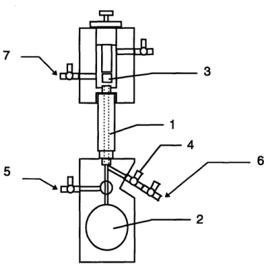
The TVE (patent pending) is a device that measures in real time the changes in clotting viscoelasticity in a sample of whole blood (Figure 1). A sample of whole blood or plasma is introduced into a cylindrical test section where it is submitted to small oscillatory perturbations. The resistance to
deformation is measured and used to calculate the elastic modulus and viscosity of the forming clot.
7
5
Figure 1. The ThromboVisco Elastogrom (TVE) is composed of a test section(1), a
bender(2), a plunger(3), a stopcock for entering sample(4), a bender solution flush(5), a saline flush(6), a vacuum(7) and a temperature regulator(not shown).
The test section was a hollow plastic cylinder lined with a silastic tubing (Figure 1(1)). The silastic tubing was used to allow the tube to deform slightly during clot retraction. This reduced the forces leading to separation between clot-surface and the inner walls of the test section, a common problem with most devices measuring clotting viscoelasticity. The test section is 2 inches long and
has an inner diameter of 0.13 inches with the tubing. The test section is oriented vertically and connected at the top end to a saline reservoir open to atmospheric
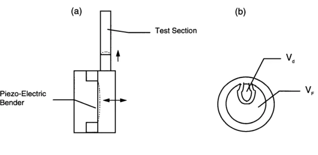
pressure and at the bottom end to a bender chamber filled with a coupling solution. The bender chamber volume is modulated by a piezo-electric (piezo-ceramic) bender (Figure 2(a)). The bender consists of a brass disk (0.010 inch thick, 1 inch diameter) bonded together with a smaller diameter piezo-ceramic disk (Figure 2(b)).
(a)
(b)
Test Section Vd Piezo-Electric VF BenderFigure 2. Side view of bender chamber (a). Schematic of the Piezo-Electric Bender (b).
The opposite side of the piezo-ceramic disk is coated with two independent electrodes: a large one, excited with a voltage VF, that serves as a force
actuator, and a second smaller electrode that provides a voltage signal, Vd, and serves as a displacement sensor (Figure 2(b)). As the actuator electrode is excited with a sinusoidal chirp signal, a net force is created on the metal disk that induces a small displacement of the bender and thus a small amplitude displacement of the blood within the test section (Figure 2(a)). The displacement signal from the bender is sampled and stored in the computer for assessment of changes in the hydrodynamic impedance of the system-thrombus combination.
Hydrodynamic impedance of the system is inferred from the transfer function between VF and Vd and reflects the mechanical stiffness of the ensemble of bender, fluid paths and thrombus. Because the properties of the bender and fluid paths are constant, changes in hydrodynamic impedance over time can be attributed to changes in the viscoelastic properties of the thrombus as it forms. A plunger is positioned above the test section. Its purpose is to seal the test fluid from atmosphere to test for gas bubbles or fluid leaks in the system. While the sample is being measured, saline prevents an air-clot interface. The device is equipped with stopcocks and reservoirs to control the fluid levels.
The software is run on a pentium personal computer fitted with a National Instruments DA board AT-MIO-16E-2 and LabView for Windows software
package (National Instruments Corporation, Austin). It's function is to control the instrument, acquire data and analyze data.
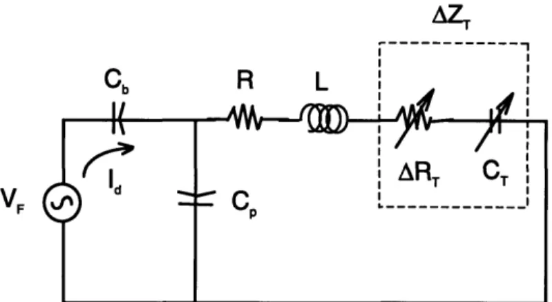
Algorithms. The system consisting of the bender, chamber, and test section tube
can be modeled, for small perturbations, as a linear analog circuit (Figure 3). The dynamics of this system are controlled by the stiffness of the bender, Kb (represented by a capacitance Cb=l/Kb), the resistance and inertance of the tube
(R and L) and the changes in impedance of the tube (AZT) created by changes in viscous (ART) and elastic (KT = 1/CT) properties of the forming clot. The voltage source (VF) models the force generated by the piezo-electric ceramic on the bender and the current represents the oscillatory flow created by the bender displacement. The potential presence of bubbles in the chamber is represented
by the parallel compliance (Cp).
AZT
--- ---
FC R L
ART
T
Figure 3. Analog Circuit model of the TVE Including a driving voltage(VF), bender
compliance(Cb), a test section resistance(R) and inertance(L), and a change in test
section impedance(AZT) represented by a change in resistance(RT) and a clot compliance(CT).
Parameters that define the behavior of this model are the resonant frequency:
o = 1/ VL*Cb
and the corner frequency:
r=
1/(R*Cb).For low Wormersley parameter, the velocity profile is parabolic. Under this condition, L and R can be approximated in terms of the tube length (I), radius (r), the fluid density (p), and the viscosity (g), as:
L=3pl/(4i a2) and R=8ftl(a 4)
The sensing electrode signal, amplified by a charge amplifier, provides a voltage
(Vd) proportional to the integral of Id and thus proportional to the bender
displacement. The frequency response of the system can be characterized by a transfer function between VF and Vd. Since VF is proportional to the force and Vd to the displacement, this transfer function scales as the complex stiffness of the system and can be represented by its magnitude and phase as a function of the excitation frequency.
The well defined cylindrical geometry of the test section, the precision and versatility of the forcing function provided by the piezo-electric bender and the minimal stray compliance of the chamber allow for the standardization of the measured parameters. These characteristics also result in an accurate and operator independent measurement of clotting function and blood viscoelasticity. Another TVE design feature is the automatic detection of bubbles and leaks. The TVE detects bubbles by comparing the signal of the isolated bender chamber with the signal of the bender chamber and closed test section. A difference in signal indicates microbubbles or leaks. We accept a 2.0% error to account for noise in the signals, but usually the error is close to 1.0%. The TVE features a temperature controlled test chamber enclosed under a thermally insulated hood. Two independent temperature controllers are involved. One forces heated air directly at the test section (controlled with a programmable proportional integral
derivative (PID) temperature controller (SysconRXC Rex C410)). This forced air helps the system to equilibrate quickly. The TVE is enclosed under a thermally insulated hood. The second system regulates the hood temperature which varies when interacting with the device (MicrOmega CN77000 Series Controller). This system helps to maintain 37 oC by eliminating fluctuations due to the
environment. The TVE also has the potential to be automated. The
characteristics that would make this possible are a simple design of blood paths and valves, small test aliquot volume, multiplexing additional channels, and most importantly a liquid-blood sensor interface which makes it self cleaning.
General Protocol
Cross Talk. Previous studies showed that there was interference between the
driving and sensing signal because of the integrated design of the actuator and sensor on the same disk. Therefore, it was necessary to measure the
interference and subtract it from the signal to get the true measurement of displacement. The interference is measured with a closed bender chamber.
Calibration Procedure. A two point calibration is conducted using saline and
calibration standard oil (n=99 cP at 37 oC). First, the calibration fluid is warmed to 37 oC. Before introducing the calibration fluid, the height of the bender coupling solution is positioned so that it is at the intersection with the sample's pathway. The fluid is then injected into the test section through stopcock 4 (Figure 1(4)). Once the fluid has passed beyond the test section, the top opening is sealed with the plunger (Figure 1(3)) and the system is left to
thermally equilibrate for 10 minutes. The calibration test is initiated, by checking for bubbles in the test section. Once the system is free from bubbles (variance of
2.0 % or less), then the plunger can be released and the measurement begun. The relationship between the oil and the saline calibration points are then used by the software to formulate the constant for the calculations of viscosity and elastic modulus in physical units.
Standard Test Procedure. The standard procedure of the TVE measurement begins by obtaining blood, or plasma, samples in sodium citrated (3.8%) siliconized glass tubes. The temperature of the tubes are maintained at 37 oC
while continuously mixing the contents. Before injecting the fluid, the height of the bender coupling solution should be positioned so that it is at the intersection of the pathway for the test fluid (See Figure 1). One cc of blood is mixed with 0.1 cc of Calcium Chloride (0.2M, end concentration of 20 mM/cc of blood) with APTT Reagenta (MDATM Platelin® L, Durham, NC) and the time registered on the
computer. The mixture is then inverted 3 consecutive times to enhance the activator to mix with the test fluid while minimizing the formation of microbubbles. The mixture is introduced into the test section through stopcock 4 slowly to avoid entrapment of bubbles. As the fluid passes beyond the top opening of the test section, the opening is sealed by moving the plunger downwards. The
measurement begins by checking for bubbles in the test section. If the test gives evidence of bubbles, additional blood is introduced to flush them away and the bubble test is repeated. Once the system is found free of bubbles or leaks, the top section is flushed of blood and filled with saline (Figure 4).
a 0.588 mg of CaCl2 combined with 20 mL of APTT Reagent
U
PlungerTest Section
Saline
Blood Sample
Figure 4. Schematic of the top portion of the TVE.
The plunger is then moved upwards and the measurement of viscoelasticity
begun. A chirp signal is emitted for a duration of 1 seconds with a pause
between excitations of 3 seconds during which the sampled signal is analyzed.
Each data point is an average of 4 samples. While the computer is acquiring
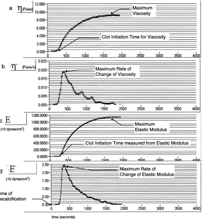
data, the program plots viscosity and elasticity in real time (Figure 5). At the end
of the test the data points collected are stored in a file for further analysis.
---
i12.000-i1 n nnn.
t.UUU-6.000- ,- "
4.00 . ... ... Clot Initiation Tim e for Viscosity... ..
2.000-
0.000-0 500 1000 1500 2000 2500 3000 3500 4000
0.025-b (Poise/s n n.n- . _. Maximum Rate of... .. .
1200.0000- 1000.0000- 800.0000- 600.0000- 400.0000- 200.0000-0.0000- -Maximum Elastic Modulus
Clot Initiation Time measured from Elastic Modulus
n nn i nn I1 nn whin Innn )nnn nn A AAI
m I I I I I I I I
0 500 1000 1500 2000 2500 3000 3500 4000
time (seconds)
Figure 5. Sample data chart of a normal volunteer's whole blood viscoelasticity vs. time (seconds). Plotted vs. time are Viscosity, 11 (a), the rate of change of Viscosity, r1' (b), Elastic Modulus, E (c) and the rate of change of Elastic Modulus, E' (d).
The following parameters were used to characterize the data: maximum viscosity (timax) and time to reach that maximum (tmax), maximum rate of change of
viscosity (rl'max) and time to reach that maximum (tn'max), maximum elastic
cE
(10 dynes/cm2
)
modulus (Emax) and time to reach that maximum (tEmax), maximum rate of change of elastic modulus (E'max) and time to reach that maximum (tE'max), and the
coagulation initiation times measured from elastic modulus (toE) and viscosity (to,) data (See Figure 5). Clot initiation times were defined as the points in time where the rate of change of the corresponding variable had a rapid change of
more than 2 percentage points of the maximum rate of change in less than 6 seconds. Interpolation was used to find the times associated with the
percentages.
Standard Clotting Tests
Standard clotting tests were conducted in the Hematology Laboratory at Massachusetts General Hospital. The MDA180 (Organon Teknika Corporation, Durham) was used to measure the Prothrombin Time (PT), Activated Partial Thromboplastin Time (APTT) and Fibrinogen Level. The STKS (Coulter Corporation, Miami) was used to measure the Platelet Count and Hematocrit. Preliminary Studies
Two preliminary studies were conducted. A first study was done to assess the TVE's measurement reproducibility. Samples of blood of normal volunteers, Fresh Frozen Plasma and diluted Fresh Frozen Plasma (1/2 saline) were studied. For each sample, measurements were conducted four times within 5 minutes of one another following the standard procedure outlined above.
A second preliminary study was conducted to determine the concentration of ReoProTM which insured full saturation of platelet GP Ilb/Illa adhesive protein
cites. ReoProTM was progressively diluted with sterile saline to concentrations of 288 gig/mL, 144 gg/mL and 36 gg/mL. Blood was collected in sodium citrated
(3.8%) siliconized glass tubes before CPB. Three syringes were each filled with 2 cc of the blood. The three blood samples were each mixed with 0.2 cc of the
increasing ReoProTM concentrations. The three samples were incubated at 37 oC
for 10 minutes on a oscillating table along with the remaining whole blood. With the prepared samples and the whole blood left in the glass tube the TVE test was conducted following the standard procedure previously mentioned. The test was repeated for a second sample collected after CPB.
We found that the change in viscoelasticity parameters caused by 144 and 288 gg/mL was negligible (See results) and thus a concentration of 144 glg/mL was used in the rest of the study to fully saturate the platelet GP Ilb/Illa adhesive proteins.
CPB Study
Blood samples of 4 mL were collected in citrated (3.8%) siliconized glass tubes from CPB patients before the administration of heparin (Figure 6(a)).
Anesthesia Heparin Protamine
Administered Administered BYPASS Administered Recovery
I
I
a
b
Figure 6. Timeline of the CPB Surgery to show when the blood samples were collected.
Two mL of blood were combined with 0.2 cc of ReoProTM at a concentration of 144 lg/mL. The ReoProTM-treated sample and the rest of the blood left in the
glass tubes were incubated for 10 minutes at 37 oC on a oscillating table. TVE tests were conducted on both samples following the standard procedure previously outlined. The tests were repeated on a second blood sample collected following the administration of protamine (Figure 6(b)).
Statistical Analysis
The data for the reproducibility study and the ReoProTM saturation study was analyzed by comparing means and standard deviations of the TVE
parameters. Multivariate analysis of variance was used to detect statistical differences and, in those found significant, paired t-tests were conducted to determine if the changes in clotting parameters were statistically significant. The significance level is defined to be less than or equal to 0.01. The significance of the correlations were determined by using the Statistica software (StatSoft, Tulsa). Multivariable linear regression was used to determine the effects of the standard coagulation tests on the TVE device parameters. The significance level
is defined to be less than or equal to 0.01. The strength of the correlation is indicated by the R value.
Results
Preliminary Studies
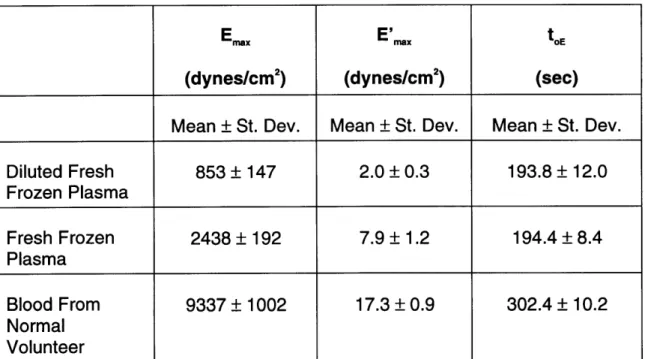
Reproducibility of TVE parameters. In the test for reproducibility, the four
measurements from each of the three samples, whole blood from a normal volunteer, fresh frozen plasma, and diluted fresh frozen plasma, indicate that the TVE results are reproducible across channels. Figure 7 illustrates the differences
in
Emax, E'maxand
toEfor each of the 3 data sets.
Emaxhad a coefficient of variance
of less than 17%, E'max of less than 15%, and toE of less than 6%, respectively (Table 1).
Diluted Fresh Frozen Plasma
1
2 3
-Fresh Frozen
Plasma Whole Blood
1 2 3 4 1 2 3 4 Channel Number Diluted Fresh Frozen Plasma 1 2 3 4 Fresh Frozen Plasma Whole Blood 1 2 3 4 1 2 3 4 Channel Number Diluted Fresh Frozen Plasma Fresh Frozen Plasma Whole Blood 1 2 3 4 1 2 3 4 1 2 3 4 Channel Number
Figure 7. (a) The maximum elastic modulus, (b) the maximum rate of change of elastic modulus, and (c) the clot initiation time for elastic modulus for the three samples tested: diluted fresh frozen plasma, fresh frozen plasma and whole blood from a normal
volunteer. 24 S12.0-E 10.0: c 8.0- 6.0-0 E4.0 w 0.0-20 18 16- 14-12 10 8.. 6- 4-350 300 250 , 200 o 150 100 50. 01
Table 1. Data from the Reproducibility Study.
E x E'nx toE
(dynes/cm2) (dynes/cm2) (sec)
Mean ± St. Dev. Mean ± St. Dev. Mean ± St. Dev.
Diluted Fresh 853 + 147 2.0 ± 0.3 193.8 ± 12.0 Frozen Plasma Fresh Frozen 2438 _ 192 7.9 ± 1.2 194.4 ± 8.4 Plasma Blood From 9337 + 1002 17.3 ± 0.9 302.4 ± 10.2 Normal Volunteer
ReoProTM Dose. We needed to find a ReoProTM concentration that would ensure
full saturation of the GP lib/Illa adhesive proteins. Therefore, we measured clotting viscoelasticity of whole blood incubated with 4 different concentrations of ReoProTM from patients before and after CPB surgery. E'max decreased as the ReoProTM dose increased to doses of 36 (p=0.01 (before), p<0.01 (after)) and
144 ug/mL (p=0.04 (before), p=0.05 (after)) (Figure 8). For concentrations higher than 144 ug/mL, E'ma did not change significantly either before or after CPB. We concluded that 144 ug/mL was enough to fully saturate all platelet GP Ilb/llla proteins.
Afr GrB Before CIB
36 144
ReoPro Dose (um/mL)
35 30 25 20 15 10 5 0 288 36 144
ReoPro dose (um/mL)
Figure 8. The effect of ReoProTM on the rate of change of elastic modulus, E',,,.
26 288
s;
N
E
o r~ a 31 (d E wCPB Study
All standard clotting tests, except the APTT, showed significant changes with CPB (See Table 2). The PT increased following CPB in every case reported with an average increase of 26%. The trend of the APTT in 8 of 14 cases was to increase and to decrease in 5. One case was left unreported due to lab error in obtaining the measurement. The platelet count deceased following CPB in every case reported with an average drop of 44%. The fibrinogen decreased following CPB in every case reported with an average drop of 45%. The hematocrit
decreased following CPB in every case reported with an average drop of 26% or
9 percentage points.
Table 2. The means and standard deviations for the results of the standard clotting tests.
Before Surgery After Surgery t test
Mean ± St. Dev. Mean ± St. Dev. p value
PT (sec) 13.00 + 0.64 16.17 ± 0.97 < 0.01
APTT (sec) 44.91 ± 24.44 34.57 ± 5.59 0.206
Platelet Count (th/uL) 187.38 + 52.51 103.93 ± 36.66 < 0.01
Fibrinogen Level 387.77 ± 80.52 223.64 ± 73.69 < 0.01
(mg/dL)
Both CPB and ReoProTM had significant effects on the TVE parameters: Emax, tEmax, E'max, tE'max, toE, T1max, timax, 11'max, tl'max,
to.
For ReoProTM-free blood, Emax
decreased following CPB (p<0.01) (Figure 9). For ReoProTM-treated blood Emaxalso decreased significantly (p<0.01). A case in which Ema, did not decrease with CPB was noted to have visible separation between the clot and the test section in the sample before CPB, explaining a lower value of Em,a than expected. The average drop in Ema, caused by CPB for ReoProTM-free blood was 20%, and 47% for ReoProTM-treated blood. E'max decreased on average by 41% following CPB in ReoProTM-free (p<0.01) and by 69% in ReoProTM-treated (p<0.01) samples.
Clotting initiation time measured from elastic modulus, toE increased an average of 72% in the ReoProTM-free samples (p = 0.03) and by 65% in the ReoProTM
-treated samples (not shown).These effects were marginally significant (p=0.03 (ReoProTM-free), p = 0.04 (ReoProTM-treated)).
ReoPro-treated E 0 C) U) 0 0 0 o 0 X E w 18 16 14 12- 10- 8-6 4 2-0 Before CPB u) N 35 E .30 u) 25 20 E 15 S10 5 0 Before CPB I I After CPB After CPB 18- 16- 14- 12- 10- 8- 6- 4- 2-0 After CPB Before CPB After CPB
Figure 9. Scatter plot of maximum elastic modulus, Emax (a) and maximal rate of change of elastic modulus, E'max (b). Lines connect measurements from each patient before and after CPB.
29
Before CPB ReoPro-free
imax decreased following CPB an average of 22% in ReoProTM-free samples (p<0.01) and an average 46% in ReoProTM-treated samples (p<0.01)
(Figure 10). 71'm decreased following CPB in all samples both ReoProTM-free
(p<0.01) and ReoProTM-treated (p<0.01). The average drop in 11'max in ReoProTM
-free samples was 42% and 53% in ReoProTM-treated samples. CPB increased the clot initiation time for viscosity, to, by 62% in the ReoProTM-free samples (p =
0.04) and by 59% in the ReoProTM-treated samples (p=0.01) (not shown).
ReoPro-free 14 12 10 a)
E
0 I I 4 2 Before After CPB CPB 0.05 0.045-0.04-1 0.035 0.03 0.0257 0.02 0.015-0.017 0.005-U I I I I Before CPB After CPBFigure 10. Scatter plot of maximum viscosity, Tl.x, (a) and maximal rate of change of viscosity, Tq'.
(b). Lines connect measurements from each patient before and after CPB.
14 12- 10- 8- 6- 4- 2-0I Before CPB 0. (u -C After CPB After CPB Before CPB II I I I -Z ReoPro-treated
ReoProTM decreased Ema, in all samples both before (p<0.01) and after CPB
(p<0.01) (Figure 11). The average drop in Em, caused by ReoProTM was 68%
before CPB and 80% after CPB. E'm, also decreased with ReoProTM in all
samples before (p<0.01) and after (p<0.01) CPB. The average drop in E'm, with ReoProTM was 71% for samples taken before CPB and 81% for samples after CPB. The effect of ReoProTM on clot initiation time measured from elastic modulus, toE, was variable and not significantly different from zero or CPB surgery (not shown).
Before CPB 200 18-16
14
12-108
6 4 2 n I 18 16 14 12 10 8 6 4 2 0 5 -50 ' ' ' .. I ... . 100 150 200ReoPro Dose (ug/mL)
0 50 100 150 50 45 40 35 30 25 20 200 200 ReoPro Dose (ug/mL)
ReoPro Dose (ug/mL)
-50 0 50 100 150 200 ReoPro Dose (ug/mL)
Figure 11. Scatter plot of maximum elastic modulus, Emax (a) and maximal rate of change of elastic modulus, E'max (b). Lines connect measurements from each patient before and after ReoProTM. 33 0 50 -50 0 50 100 150 50-: 45 -40 -35 30-25 - 20-15 10- 5-0 -C%4 E a) 0 E lu I, -50
I! IIII I]F ~ M . .. III Il l I I II . I i
' ' ' 'r ~ ' ' ' ' ' ' ' '
The addition of ReoProM T decreased TIma in all samples both before (p<0.01) and
after (p<0.01) CPB (Figure 12). The average drop in ilm, caused by ReoProTM was 65% before CPB and 77% after CPB. 11'm, decreased with ReoProTM in all
samples both before (p<0.01), and after (p<0.01) CPB. The average drop in ql'max
with ReoProTM was 66% before and 77% after CPB. The clot initiation time
measured from viscosity, to., did not change with ReoProTM or CPB (not shown).
Before CPB 14 12 10-8 6 4 2 A--50 0 50 100 150 200 200 ReoPro Dose (ug/mL)
0.05 0.045 0.04 0.035 "O' 0.03 - 0.025 0.02 E c 0.015 0.01 0.005 14 12 10 8 6 4 2 -50 0 50 100 150 ReoPro Dose (ug/mL)
0.05 0.045 0.04 0.035 0.03 0.025 0.02 0.015 0.01 0.005 -50 0 50 100 150 200
ReoPro Dose (ug/mL)
-50
200
0 50 100 150 200
ReoPro Dose (ug/mL)
Figure 12. Scatter plot of maximum viscosity, 1qmax (a) and maximal rate of change of
viscosity, Tl'max (b). Lines connect measurements from each patient before and after
ReoProTM.
35
j _L- -1- ~_IIIL ~ ~.. I~-;- --- -- ...~ - -- I I-.PI .. I I-~- -.-. I~PI~1
Table 3. Means and standard deviations of the TVE measurements.
ReoProTM-free ReoProT"-treated % change due to CPB % change due
to ReoProTM
before after before after ReoPro- ReoPro" - before after
free treated CPB CPB Emax 11971 ± 3194.4 9147.1 ± 1947.6 3552.0 ± 939.2 1775.2 ± 508.6 -20* -47* -68* -80* (dyneslcm2) tEmax (sec) 1164 ± 414 1896 ± 618 1572 ± 456 2364 ± 654 +101* +70* +55 +30* E'max 32.5 + 8.6 18.4 ± 6.4 9.8 ± 4.8 3.5 ± 1.5 -41* -69* -71* -81* (dynes/cm2s) tE'max(sec) 354 102 690 ± 588 360 ± 156 660 ± 588 +94 +85 -1 -7 toE (sec) 264 ± 78 468 ± 330 282 + 108 462 ± 312 +72 +65 +5 +1 11max (poise) 9.7 ± 2.5 7.2 ± 1.5 3.3 ± 0.8 1.6 ± 0.5 -22* -46* -65* -77* timax (sec) 1182 ± 408 1938 ± 648 1506 ± 408 2418 ± 636 +87 +68* +46* +29* Tl'max (poise/s) 0.027 ± 0.008 0.014 ± 0.005 0.010 ± 0.004 0.003 ± 0.001 -42* -53* -66* -77* tmax (sec) 408 ± 108 762 ± 582 414 ± 156 726 + 624 +76 +66 -2 -10 to (sec) 264 ± 84 456 ± 324 264 ± 108 408 ± 186 +62* +59* -3 -1
* Represents a statistically significant change.
Standard Clotting Tests. The time to the maximum elastic modulus, tEmax, had a
positive corelation with PT in both the ReoProTM-free samples (R = 0.65 p<0.01)
and the ReoProTM-treated samples (R = 0.60 p<0.01). tEmax had no correlation
with APTT (R = -0.13 p=0.55 (ReoProTM-free), R = -0.03 p=0.87 (ReoProTM
-treated)). The time to the maximum viscosity, tnma, had no significant correlation in the ReoProTM-free samples (R = 0.35 p=0.08), but had a positive correlation in the ReoProTm-treated samples (R=0.59 p<0.01). There was no correlation
between tnmax and APTT (R = -0.21 p=0.32 (ReoProTM-free), R = -0.15 p=0.49
(ReoProTM-treated))
The time to the maximum rate of change of elastic modulus, tE'max, had a
positive correlation with PT in both the ReoProTM-free samples (R = 0.68 p<0.01) and the ReoProTM-treated samples (R = 0.60 p<0.01). There was no
significant correlation between tE'max and APTT (R = 0.21 p=0.31 (ReoProTM-free), R = 0.41 p=0.05 (ReoProTM-treated)). The time to the maximum rate of change of viscosity, t,'ma, was not significantly correlated with the PT in the ReoProTM
-free samples (R = 0.14 p=0.51), although it had a positive correlation in the ReoProTM-treated samples (R = 0.52 p<0.01). t,max had no correlation with APTT
(R = -0.01 p=0.98 (ReoProTM-free), R = -0.05 p=0.82 (ReoProTM-treated)).
The clot initiation time measured by the elastic modulus, toE, had a positive correlation with PT for the ReoProTM-free samples (R = 0.62 p<0.01)
and for the ReoProTM-treated samples (R = 0.60 p<0.01). There was no correlation between toE and APTT (R = 0.28 p=0.18 (ReoProTM-free), R = 0.40
p=0.05 (ReoProTM-treated)). The clot initiation time measured by viscosity, ton,
had no correlation with PT in the ReoProTM-free samples (R = 0.13 p=0.54), yet had a positive correlation in the ReoProTM-treated samples (R=0.69 p<0.01).
There were no correlations between to, and APTT (R = 0.06 p=0.77 (ReoProTM
-free), R = 0 p=0.99).
TVE Parameters. There was a linear relation between the Em, and Im, (R =
0.99 p<0.01). The correalation had a clustering of the data with respect to CPB
and the adding of ReoProTM (See Figure 13). The samples after CPB are clustered for Em,<5000 dynes/cm2s and am,,<5 poise.
18 16- 14- 12-. 10-0. S8-* E 6- 4-2 0 0 2 4 6 8 10 12 14 16 18 Emax (1000 dynes/cmA2)
Figure 13. Scatter plot of maximum elastic modulus (Emax) vs. the maximum value of viscosity (irmax) (R = 0.99). The plot includes before CPB samples, ReoProT"-free (4) and ReoProw"-treated (*), and after CPB samples ReoProT-free (*) and ReoProTm-treated (0).
Emax was positively correalated with E'max (R = 0.89 p<0.01)(Figure 14). There was, however, substantial variability in the relationship between those variables for individual datapoints.
50- 45- 40- 35- 30- 25- 20- 15- 10- 5- 0-0 2 4 6 8 10 12 14 16 18 6 8 10 12 14 16 18 Emax (1000 dynes/cm^2)
Figure 14. Scatter plot of maximum modulus of elasticity (Emax)and the maximal rate of change of elastic modulus (E'max) (R = 0.89). The plot includes before CPB samples,
ReoProm-free (*) and ReoPro-treated (,), and after CPB samples ReoProT-free (*) and ReoProw-treated (®). 39 -N E a) E lu 6 4b 4 4 * 4b 6* 4 4 * *
Relationship between TVE derived parameters and standard clotting tests. E'max was found to have a positive correlation with platelet count (R = 0.72 p<0.01). The effect of CPB is visible from the clusters of the before and after CPB data. The samples collected before CPB had in general higher E'm and a higher platelet count compared to the samples after CPB.
50- 45-40 CD 35 30-S25 x 20 E L, 15 10-5 0- I' I I I I I I I . . .I . . . . I . . . .I I . I . I . 50 100 150 200 250 300 350
Platelet Count (1000/uL)
Figure 15. Plot of maximal rate of change of elastic modulus (E'max) vs. platelet count (R = 0.72). The plot includes ReoProW-free samples before (+) and after (®) CPB.
40
0
There was a weaker correlation between E'ma in ReoProTM-treated samples (residual E'm.) and platelet count (R = -0.55 p<0.01) when pooling all the data before and after CPB (Figure 16). The correlation was not significant when the data was analyzed in separate groups (R = 0.01 p=0.96 (before), R = 0.21
p=0.48 (after)).
251
E "0C E lu 0 20 15- 10- 5-f ~~~ . . . . . . . . . . . . . . . 50 100 150 200 250Platelet Count (1000/uL)
Figure 16. Plot of the maximum residual rate of change of elastic modulus (residual E'max) vs. platelet count (R = 0.42). The plot includes ReoProT-treated samples before (,) and after (0) CPB.
I 3
The difference between E'm,, of ReoProTM-free samples and the corresponding residual E'm,, (AE'max) was also positively correlated with platelet count (R = 0.78 p<0.01) (Figure 17). 40 35-A 30-'1 25-x EulS U 15 " 0 0 S10- 5-0 50 100 150 200 250 300 350 400
Platelet Count (1000/uL)
Figure 17. Scatter plot of delta E'max, the difference between E'max of ReoPro"-free
samples and the corresponding residual E'max, (AE'max) vs. platelet count (R = 0.78). The
plot Includes samples before (,) and after (®) CPB.
There was also a strong positive correlation between E'm,,ax and fibrinogen (R = 0.84 p<0.01) (Figure 18).
0 100 200 300 400 500
Fibrinogen (mg/dL)
600
Figure 18. Plot of maximal rate of change for elastic modulus (E'max) vs. fibrinogen concentration (R = 0.84). The plot includes ReoPro"-free samples before (,) and after (®) CPB.
Residual E'max was positively correlated with fibrinogen concentration both
before and after CPB (R = 0.75 p<0.01 (before) , R = 0.82 p<0.01 (after)). The data before CPB appears to have a steeper slope than the slope of the data after CPB (Figure 19). Combining the data sets still gives a significant correlation (R = 0.83 p<0.01). 25 Ou20-cu E .,15-'0 x CU -E L, 10-0)
nr
5-100 200 300 400 500 600 Fibrinogen (mg/dL)Figure 19. Scatter plot of maximum residual rate of change of elastic modulus (residual
E'max) vs. fibrinogen concentration (R2 = 0.83). The plot includes ReoPro"'-treated
samples before (*) and after (®) CPB.
®4
E'max had a weak correlation with hematocrit that was only marginally significant (R = 0.42 p=0.03) (Figure 20). 50-45 40 35 E 30 25 9 20 E 15 10 5 0 0 35 40 4
Figure 20. Scatter plot of maximal rate of change of elastic modulus (E'max) vs. hematocrit (R = 0.42 ). The plot Includes ReoPro"-free samples before (,) and after (@) CPB.
45 5 10 15 20 25 30 Hematocrit 4 0
90
0
We used multivariable linear regression analysis to explore the relationship between standard clotting parameters and E'ma. We found that residual E'mx could be expressed in terms of fibrinogen concentration (FIB) and the hematocrit
(HCT) giving the model:
Residual E'm, = 0.041 * FIB - 0.198 * HCT Eq. 1
(R = 0.85 p<0.01). Thus, fibrinogen has a positive influence on residual E'max, hematocrit has a negative influence to the correlation (Figure 21). There was no significant contribution of platelet count on residual E'm,.
25-u) E (1)20-0 - 10- 15-E, 0 5 10 15 20 25
Predicted Residual E'max (dynes/cmA2s)
Residual E'max = 0.041 * FIB - 0.198 * HCT
Figure 21. Maximal rate of change of elastic modulus of ReoProT-treated blood samples (residual E'max) vs. predicted values using the linear regression model in equation 1. The plot includes ReoProTm-free samples before (*) and after (®) CPB.
E'ma could be expressed in terms of platelet count (PLT) and fibrinogen concentration (FIB) rendering the model
E'max = 0.067 * PLT + 0.055 * FIB Eq. 2
(R = 0.94 p<0.01). Both platelet count and fibrinogen concentration have a positive contribution to E'm, (Figure 22).
45 40- 30-2 00 35-E 20 15 210- 0 5 0-0 5 10 15 20 25 30 35 40 45 50 Predicted E'max (dynes/cmA2s)
E'max = 0.067 * PLT + 0.055 * FIB
Figure 22. Maximal rate of change of elastic modulus of ReoProT-free blood samples (E'max) vs. predicted values using linear regression model in equation 2.
E'max could better be expressed in terms of platelet count (PLT), fibrinogen concentration (FIB) and hematocrit (HCT) yielding the relationship:
E'mx = 0.092 * PLT + 0.070 * FIB - 0.309 * HCT. Eq 3
The calculated values have a high degree of correlation with the measured value (R2 = 0.96 p<0.01) (Figure 23). Thus, while PLT and FIB have a positive
contribution to E'ma, HCT has a negative contribution. All three parameters had statistically significant contributions to E'max.
50-45 N 40 -E 35
0-0 5 10 Predicted E'max (dynes/cm2515 20 25 30 35 40 45 50
,20
5
0-0 5 10 15 20 25 30 35 40 45 50
Predicted E'max (dynes/cmA2s)
E'max
=
0.092 * PLT + 0.070 * FIB - 0.309 * HCTFigure 23. Maximal rate of change of elastic modulus of ReoProT-free blood samples (E'max) vs. predicted values using the linear regression model in equation 3 (R2 = 0.96).
The plot Includes ReoProTm-free samples before (*) and after (@) CPB.
Residual E'ma, ReoProTM-treated data, plotted against predicted values obtained from equation 3 has a different slope from the line through the ReoProTM-free data points (Figure 24).
0 5 10 15 20 25 30 35 40 45
Predicted E'max
Emax= 0.092 * LT+ 0.070 *HFB- 0.309 *1
Figure 24. Maximal rate of change of elastic modulus of ReoProm-free and ReoPro
m-treated blood samples (E'max) vs. predicted values using the linear regression model in
equation 3 (R2
= 0.96). The plot includes ReoProm-free samples before (*) and after (®)
CPB and ReoPro1"-treated samples before (A) and after (*) CPB.
Discussion
The major findings of this study are: 1) The TVE device is capable of determining with accuracy quantitative changes in blood viscoelasticity during clotting; 2) The TVE-derived coagulation parameters Emax, E'max, ilmax, and i'max
and the coagulation parameters PT, platelet count, fibrinogen concentration and hematocrit are all affected by CPB; 3) The TVE-derived parameters were all substantially reduced by incubation of the blood with the platelet GP inhibitor ReoProTM suggesting that these parameters are exquisitely sensitive to platelet function; and 4) In ReoProTM-free blood samples, values of E'mx for all patients,
before and after CPB, could be predicted as a function of platelet count, fibrinogen concentration and hematocrit.
The viscoelasticity of a blood clot is a measure of clot rigidity17. By examining the viscoelasticity as the clot is being formed, information about the clot strength, the rate of formation and times associated with that formation can be extracted. This information has been postulated to be an important predictor of post CPB bleeding"7 as well as a guide for selection of blood products for its
treatment. The TEG, SONOCLOT, Vilastic 3 and Hemodyne are devices available to assess the viscoelasticity of a blood clot.
The Thromboelastograph (TEG) was the first device to track the changes in elastic properties of a blood clot as it forms and as it dissolves during
fribrinolysis. A TEG (Figure 22(A)) consists of a cylindrical cup into which a specimen of whole blood is introduced. A vertical pin, suspended by an elastic
torsion wire, is lowered into the center of the blood specimen cup and the blood surface is covered with mineral oil to prevent evaporation. The cup is rotationally oscillated around its vertical axis at a frequency of 2 Hz with an amplitude
between 4 and 5 degrees and an angular velocity, o. The rotation of the vertical pin induced by the rotation of the blood is continuously recorded on a chart as a function of time. Monitoring by TEG has been found to be useful to guide peri-operative blood replacement therapy18.
P(t)
d(t)
t
AdFigure 25. Schematic representations of the TEG (A), SONOCLOT (B), Vilastic (C) and the
Hemodyne (D) methods to assess clot viscoelasticity.
Although TEG has been approved for clinical use to assess clotting function, the method has not gained widespread acceptance as a clinical tool. This limited acceptance is, at least in part, due to a perceived low benefit/cost
ratio, poor reproducibility and the technically demanding nature of the test. Because TEG uses an open cylindrical cup into which the blood is poured, the volume of the sample is critical and introduces a source of variability. Also, gas bubbles and surface tension effects can cause the sample to adhere
asymmetrically to the cup's side walls resulting in an irregular and inconsistent geometry. A second cause for low clinical acceptance of the TEG test is the qualitative nature of the derived parameters. Except for the time based
parameters, all other parameters derived from the TEG amplitude are reported in arbitrary units (mm of a plotter scale) and not in physical units. Interpretation of the TEG tracing is also highly subjective and questionable. For example, the drop in the TEG signal amplitude occurring over time after a maximal amplitude is currently attributed to the process of fibrinolysis. However, such a drop in amplitude may be the result of separation between the clot and the pin, or the cup, caused by clot retraction (a desirable physiologic process) instead of fibrinolysis (an undesirable process). Ultimately, clinical interpretation of the
TEG is based on empirical and subjective pattern recognition.
The physical principle and operation of the SONOCLOT is similar to that of TEG. A cylindrical probe is lowered into an open cuvette, and is vibrated with an amplitude of 1 im (Ad) at a frequency of 200 Hz (Figure 22(B)). As the
thrombus forms and mechanical forces begin to impede the motions of the probe, the device adjusts the driving force amplitude (AF) to maintain a constant displacement amplitude. The change in driving force reflects the mechanical
impedance imposed on the probe by the clot and is plotted as a function of time as an index of clot stiffness.
The SONOCLOT shares the same basic problems as the TEG:
1) technically demanding; 2) poor reproducibility caused by variability in sample
size and geometry; 3) a measurement parameter which is device specific, and thus cannot be calibrated or directly correlated with mechanical properties in physical units; and 4) it shows a drop in impedance over time in normal and abnormal samples which could be interpreted as fibrinolysis or by a separation of contact between the clot and the probe. Finally, as with the TEG,
interpretation of the SONOCLOT "signature" is empirical and highly subjective. This Vilastic 3 represents a fundamental improvement from the TEG and the SONOCLOT in that it provides measurements of the thrombus viscosity and elastic modulus in physical units. The device (Figure 22(C)) consists of a fluid-filled chamber and electromagnetically driven piston connected to the upper end of a vertical cylindrical tube (1 to 3 mm ID, 50 mm long, 0.060-0.56 mL volume). Blood to be analyzed is withdrawn through the lower end of the tube from a sample cup until it fills the whole length of the tube. The piston is oscillated with a displacement (d(t)) which induces a sinusoidal oscillatory flow in the blood sample at a frequency that can be selected from 0.01 to 40 Hz. Simultaneously, sinusoidal pressure variations induced in the chamber are sampled and
analyzed by a computer. Data reduction in the Vilastic system is based on the
theory of oscillatory flow in cylindrical tubes 9'2. Because the measurements are
performed in a well defined geometry, they yield robust and reproducible data. Despite the fundamental improvements over the TEG and SONOCLOT methods, the Vilastic 3 oscillatory flow technique has a number of weaknesses which complicate its use as a routine clinical instrument. The cost of
electromechanical and pressure transducers make the instrument expensive
($20,000 per test section). The Vilastic's measurement accuracy depends on the
assumption of a total absence of leaks or air bubbles in the tube and chamber. However, the instrument does not allow the user to test for the presence of leaks or bubbles. Blood density has to be assumed or measured in a separate test. The manual loading of the sample and debubbling are technically elaborate, time consuming and not amenable to automation. Although the instrument is
interfaced and controlled by a computer, the commercial device is designed to handle a single test section.
The hemodyne clot retractometer was designed to measure platelet force development (Figure 22(D)). Under a small amplitude oscillatory perturbation, the relation between force and displacement is related to elastic modulus17.
Clots are formed in a temperature controlled cup. Before a clot begins to form, an upper plate is positioned on the surface and in the center of the clotting
solution. Clot adheres to the inner walls of the cup and to the bottom of the plate. Silicon oil is used to cover the small amount of the clot that is exposed to air on the perimeter of the plate. A force displacement transducer coupled to the upper
plate via a threaded, stainless steel arm is used to measure the vertical force on the plate.
The hemodyne, like the other 3 devices, also experiences separation. Active clot retraction due to the presence of platelets was well summarized by Carr". He explained that fibrin strands conform with the platelet surface as platelet pseudopods are extended out along fibrin clusters. The contraction of microfilaments cause the platelets to constrict. As platelets constrict, fibrin strands are pulled and tension development begins. These forces are
transferred to the clot surface. When the forces are great enough to overcome the attachment of the clot to a test section, the clot separates from the test section wall.
The TVE design has some advantages over the 4 devices mentioned. The TVE uses low cost Piezo-electric technology and can be calibrated to viscosity and elastic modulus standards. It can mathematically eliminate
variability in sample tube geometry by measuring the viscoelasticity for 2 fluids with known viscosities and determining a section specific calibration factor. As
illustrated by the first preliminary study, the TVE is reproducible (Figure 7). The TVE is also practical in that it can produce results in less than 20 minutes. The time required to obtain the E'm, test result, tE'max, was on average 6 minutes for
pre-bypass samples and 11.5 minutes for post-bypass samples. Taking into account the time to deliver the specimen to the Hematology Laboratory, E'ma could be obtained in less than 15 minutes.
The TVE has its limitations. Because calcium chloride is added to the blood before the sample is introduced into the test section there is a limited amount of time to enter the sample. This problem could be eliminated in an automated device. Depending on the material of the test section, the TVE can also experiences separation. However, a silastic test section lining virtually eliminates clot separation in the samples studied. Further improvements may be possible with refinements of the test section design.
The protocol for the CPB study was designed to optimize the conditions for clot formation. In our study, we use 20 mM of calcium chloride to activate clot formation. Doubling the calcium concentration from 10 mM to 20 mM has a minimal increase in force development in platelet rich plasma". This finding assured us that 20 mM was enough to fully activate the clot. APTT Reagent was also added to accelerate the TVE measurement so that clot formation would take place before sedimentation. The APTT test uses this reagent in a 1:1 ratio with the sample. We chose to use a 1:10 ratio of the APTT Reagent with our samples because a 1:1 ratio of the solution would dilute the concentrations of blood components. The temperature controllers maintain the TVE at 370C. This was important because the rates of clot formation and platelet force development are dependent on temperature". A decrease in temperature, from 370C to 270C,
also decreases the rate and magnitude of total force development. At 420C, clot retraction is irreversibly inhibited. The temperature 370C was found to be a temperature for the optimal clot formation. The ReoProTM concentration used in
the CPB study was 144 gg/mL. Our preliminary studies show that concentrations above 144 gg/mL did not decrease the viscoelasticity further.
The maximum rate of change of elastic modulus, E'mx, was used to represent the TVE parameters in correlations with standard clotting test results. Advantages of this parameter are that it provides a faster turnaround time, considering E'm, occurs earlier than Em,, and better reproducibility, since it is less likely to be affected by separation. E' reaches a maximum soon after the onset of coagulation. This is usually within 9 minutes from the start of the test (Table 3). Separation is observed at a later time after the clot begins to retract. The high correlation between Em, and the maximum viscosity, nmx, allows assessment of one of these parameters to be enough to characterize the other. The correlation also implies a constant structural damping of the clots. Emax, being about a factor of 10 larger than Tlmax, is a more robust parameter. The
positive correlation between Em,a and E'm, also suggests that Ema, can be estimated from E'mx.
Adding ReoProM T to the test provides two new TVE parameters: residual
E'm. and delta E'ma. The residual E'ma may be interpreted as the fraction of E'm, independent of platelet function and therefore reflects the contribution of all soluble factors that remain active after the addition of ReoProTM. Delta E'ma is the difference between E'ma and residual E'ma and reflects the contribution of
platelet function.
Effects of CPB on coagulation parameters. Both standard clotting tests
parameters and the TVE-derived parameters decreased as a result of bypass. Hemodilution, lysis and the platelet fragmentation due to the increased shear stress from the bypass are all possible contributors to the decrease. The in vitro addition of ReoProTM also decreased the TVE parameters. This result indicates impairing platelet function reduced clot viscoelasticity, a result consistent with the findings of Carr1. He observed a decrease in the force development and
elastic modulus after incubation of the blood with a platelet adhesive protein antibody.
Correlations between TVE-derived parameters and standard clotting tests.
Correlations between the TVE parameters (Emax, E'max, m,,, and
l'mx)
and platelet count suggest the important contribution of platelet activity to clot viscoelasticity. The correlation between platelet count and E'ma suggests that the clotting viscoelasticity in CPB patients is affected by platelet count. There was no correlation between the platelet count and the residual E'mx. Clearly, the addition of ReoProTM eliminated the contribution of the platelet activity to E'ma asthe GP Ilb/Illa adhesive proteins were saturated. The correlation between platelet count and delta E'max was stronger than that with E'max as delta E'max tends to isolate contribution of platelet activity to the formation of the clot.
Fibrinogen was highly correlated with E'max, indicating that viscoelasticity also has a fibrinogen component. The positive correlation between fibrinogen