HAL Id: hal-01877913
https://hal.archives-ouvertes.fr/hal-01877913
Submitted on 20 Sep 2018HAL is a multi-disciplinary open access archive for the deposit and dissemination of sci-entific research documents, whether they are pub-lished or not. The documents may come from teaching and research institutions in France or abroad, or from public or private research centers.
L’archive ouverte pluridisciplinaire HAL, est destinée au dépôt et à la diffusion de documents scientifiques de niveau recherche, publiés ou non, émanant des établissements d’enseignement et de recherche français ou étrangers, des laboratoires publics ou privés.
miniaturized fluorescence sensing device
Daniel Măriuța, Lucien Baldas, Jürgen Brander, Stéphane Le Calvé, Stéphane
Colin, Christine Barrot-Lattes, Pascale Magaud, Nicolas Laurien
To cite this version:
Daniel Măriuța, Lucien Baldas, Jürgen Brander, Stéphane Le Calvé, Stéphane Colin, et al.. De-sign, optimization and manufacturing of a miniaturized fluorescence sensing device. 3rd MIGRATE International Workshop, Jun 2018, Bastia, France. pp.210421. �hal-01877913�
1
MIGRATE2018:210421
DESIGN, OPTIMIZATION AND MANUFACTURING OF A
MINIATURIZED FLUORESCENCE SENSING DEVICE
Daniel Măriuța
1,2, Lucien Baldas
1, Jürgen J. Brander
2,
Stéphane Le Calvé
3,4, Stéphane Colin
1, Christine Barrot-Lattes
1, Pascale Magaud
1,
Nicolas Laurien
11
Institut Clément Ader (ICA), Université de Toulouse, CNRS, INSA, ISAE-SUPAERO, Mines-Albi, UPS, Toulouse France
2
Karlsruhe Institute of Technology, Institute of Microstructure Technology, Campus Nord, Hermann-von-Helmholtz-Platz 1, 76344 Eggenstein-Leopoldshafen, Germany
3
University of Strasbourg, Institute of Chemistry and Processes for Energy, Environment and Health (ICPEES), Group of Atmospheric Physical Chemistry, Strasbourg France.
4In’Air Solutions, 1 rue Blessig, Strasbourg, France
KEY WORDS
Computational aided design, residence time distribution, disposable fluidic cell, micro-fabrication, low volume liquid detection, computational fluid dynamics
ABSTRACT
This work is part of a larger effort to miniaturize a microfluidic formaldehyde sensing device recently developed and commercialized by InAirSolutions Strasbourg1. The detector is already an innovation in the field being capable to detect continuously formaldehyde concentrations lower than 1 ppb in stabilized conditions and long range campaigns, fulfilling the new imposed regulations in the field of indoor air pollution [1]. The sensing device works in four steps: i) gas sampling, ii) trapping of formaldehyde from air to a liquid reagent, iii) derivatization reaction with acetylacetone solution at 65°C producing a fluorescent compound (DDL), iv) colorimetric detection employing a commercial fluorescence detection system. Apart of increasing significantly the overall price of the system, the commercial fluorescence systems has a large dead volume decreasing the response time of the measurement process and increasing the necessary liquid flow rate. Starting from this current situation, one of the project goals is to develop a cheap miniaturized fluorescence sensing system. Finally, the aim is to develop an ultra-portable formaldehyde sensing device with larger autonomy and shorter response time compared to the current device, using the state of the art in the field of micro-fabrication, opto-fluidics and gas-liquid trapping/contacting.
One of the major challenges in field of lab-on-a-chips is the integration of fluorescence optical sensors in ultra-portable, low maintenance, low power consumption, sensitive, reproducible and cheap platforms for small liquid samples sensing. Since the emergence of this field three decades ago, progress has been registered and different integration strategies of the fluorescence optical components have been tested by different research groups. Starting from the latest achievements to our knowledge in this field [2-5], a simple and relatively low-cost fluorescence sensing platform has been designed,
1
2
manufactured and preliminarily tested. Classical fluorescence optical sensing systems include light sources, light guides, wavelength-selection components, light detectors, fluidic chambers and signal processing/transmitting electronics. The ideal on-chip fluorescence sensing platform might be alignment-free, technician independent, compact, insensitive to shock and vibration, low maintenance and low power needed, fast response, usable under extreme environment, enabled for multi-target detection and selective.
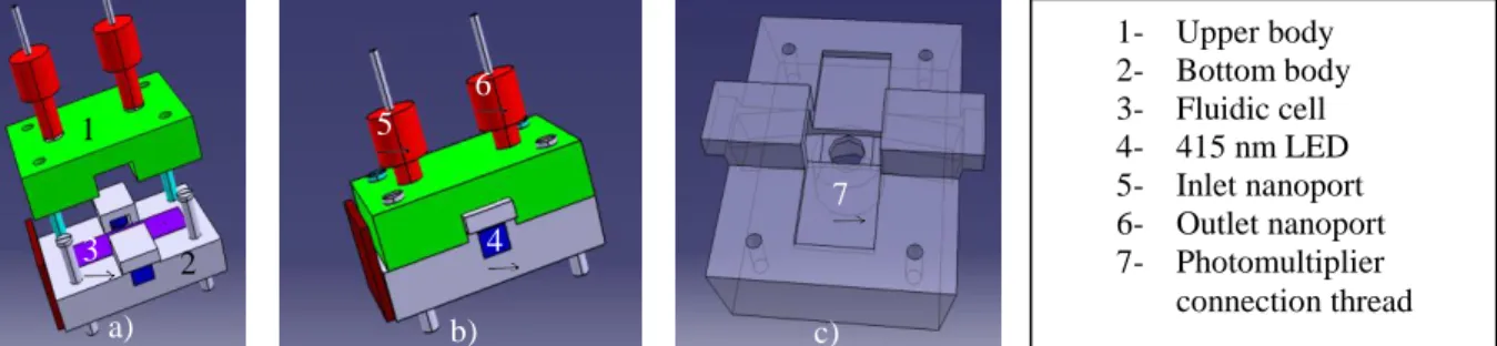
Starting from the designs proposed by Shin et al. [2], an excitation configuration avoiding direct illumination of the surface of the photon detector was considered (Fig. 1). The system was designed to integrate a fully disposable fluidic cell. Fluidic inlet and outlet connections were designed using nano-port connectors (N-333, Idex-HS) integrated in the upper body of the system enabling their re-usage by avoiding direct bonding on the surface of the fluidic part.
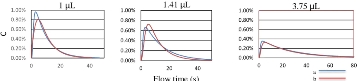
The internal geometrical configuration of the fluidic cell (micro channel hydraulic diameter connecting the inlet and the outlet with the detection chamber and detection chamber itself) was designed starting from the initial constraints of the project (liquid flow rate – 10 µL/min, inlet channel’s hydraulic diameter – 200 µm, photomultiplier detection surface - circular collection lens with 5 mm in diameter. Considering the small ratio between the depth and maximum possible dimension of the detection chamber (0.2/5), an optimization process of stream dynamics was conducted implementing a CFD approach in commercial software Ansys Fluent. Therefore, fluidic residence time distribution (RTD) inside the cell was optimized. By analyzing RTD curves, the configurations were iteratively updated in order to avoid dead volumes or large stream velocity differences in the detection chamber. RTD was calculated using the pulse method. A tracer was injected at the inlet at time t=0. Species concentration at the inlet was 𝐶 = 𝐶𝑚𝑎𝑥 for the first time step and for further steps was decreased at zero. Area-weighted-averaged concentration of the tracer at the outlet was monitored with time to obtain the RTD curves. A similar simulation was performed for the commercial cell and the results obtained in terms of peaks of tracer concentration at the outlet were
Fig. 1: Fluorescence sensing device. CAD concept. a) Exploded vision b) Assembled system c) 3D
visualization of bottom part comprising illumination system, fluidic cell insertion aperture and photomultiplier connection thread
1- Upper body 2- Bottom body 3- Fluidic cell 4- 415 nm LED 5- Inlet nanoport 6- Outlet nanoport 7- Photomultiplier connection thread 6 . 1 3 . 2 . 5 . 4 . 7 . c) b) a)
Fig. 2: Flow field velocity distribution in detection chamber: 1. 1µL detection volume, a. one inlet channel, b. two inlet channels; 2. 1.41 µL detection volume, a. one inlet channel, b. three inlet channels; 3. 3.75µL
detection channel, a. one inlet channel, b. three inlet channels
1a 1b
2a 2b
3
used as an etalon for the optimization process of the fluidic cell. The mean residence times was calculated as:
𝑡̅ =∑ 𝑡𝑖 𝑖𝐶𝑖
∑ 𝐶𝑖 𝑖 (1)
The aim of this process was to achieve, as far as possible, a uniform distribution of the flow field velocities in the detection chamber. Several configurations were obtained and considered for being manufactured and tested with detection volumes ranging from 1µL to 3.75 µL (Fig.2-3).
Once the fluidic optimization was done, a fabrication process was identified considering non-absorbent and cheap materials. A three layer configuration of the fluidic cell was proposed for the fabrication process (see Fig. 4). The first layer was quartz (500 µm thickness) in order to assure a good light transmittance to/from detection chamber, middle layer was SU-8 (200 µm thickness) and third layer (400 µm), where the inlet and outlet were etched vertically, was silicon. Wet etching of the inlet and outlet channels was performed using a KOH solution. Fabrication masks necessary for SU-8 etching have been designed using QCAD software.
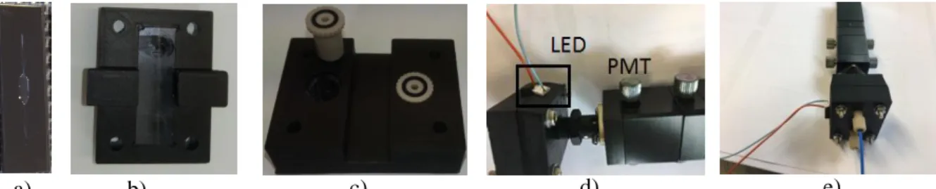
A first experimental campaign was performed in ICPESS Strasbourg to verify the proof of concept (Fig. 5, d-e). The prototype substituted the commercial fluorescence detector in the experimental set-up developed here for formaldehyde concentration measurements and no leakage was observed during the tests. Formaldehyde concentrations were varied subsequently in order to analyze the signal output read by photomultiplier. Unfortunately, the signal output was similar whatever the
0.00% 0.20% 0.40% 0.60% 0.80% 1.00% 0 20 40 C 0.00% 0.20% 0.40% 0.60% 0.80% 1.00% 0 20 40 0.00% 0.20% 0.40% 0.60% 0.80% 1.00% 0 20 40 60 80 Flow time (s)
Fig. 3: Residence time distribution curves as area-weighted averaged concentrations at the outlet as a function
of flow time
1 µL 1.41 µL 3.75 µL
a b
Fig. 4: Fluidic cell manufacturing process flow. a) SU-8 layer deposition on quartz layer. b) UV mask
illumination c) Thermal treatment. d) SU-8 developer, rinsing. e) KOH etching. f-g) Conical configuration of inlet and output channels. h) Bonding parts g. and d. by thermal treatment. i) longitudinal cross section. j) 3D structure of the fluidic cell
a. b. c. d. e. f. g. h. i. j.
4
formaldehyde concentration. Further tests are envisaged, but a partial conclusion emphasize the reflectance of the light beam due to the mirror effect of the silicon layer.
Conclusions. Further work
A first fluorescence sensing prototype with a disposable detection cell was designed, manufactured and preliminary tested. Fluidic configurations of the detection cell were optimized by calculating iteratively the residence time distribution curves in Ansys Fluent. A detection cell was embedded into a two-bodies black plastic box incorporating simultaneously two 415nm LEDs in such a configuration to avoid direct illumination of the photomultiplier. The system was experimentally verified and leakage-free proof was confirmed. Unfortunately, fluorescence signal couldn’t be detected most probably due to the fact that a large part of the light illuminating the detection cell was reflected and collected by photomultiplier decreasing very much the signal-to-noise ratio. Further work will include the substitution of the top silicon layer with a non-molecule absorbent and non-reflecting polymer (i.e. PTFE, PEEK) and replacement of the current PMT with a miniaturized photon detector. Acknowledgements
This project has received funding from the European Union’s Framework Programme for Research and Innovation Horizon 2020 (2014-2020) under the Marie Sklodowska-Curie Grant Agreement No. 643095.
References
[1] Guglielmino, M., Allouch, A., Serra, C. A., & Le Calvé, S. (2017). Development of microfluidic analytical method for on-line gaseous Formaldehyde detection. Sensors and Actuators B: Chemical, 243, 963-970.
[2] Shin, Y. H., Barnett, J. Z., Gutierrez-Wingb, M. T., Ruschb, K. A., & Choia, J. W. (2017, February). A portable fluorescent sensing system using multiple LEDs. In Proc. of SPIE Vol (Vol. 10061, pp. 100610M-1).
[3] Babikian, S., Li, G. P., & Bachman, M. (2017). A Digital Signal Processing-Assisted Microfluidic PCB for On-Chip Fluorescence Detection. IEEE Transactions on Components, Packaging and Manufacturing Technology, 7(6), 846-854.
[4] Shu, Z., Kemper, F., Beckert, E., Eberhardt, R., & Tünnermann, A. (2017). Highly sensitive on-chip fluorescence sensor with integrated fully solution processed organic light sources and detectors. RSC Advances, 7(42), 26384-26391.
[5] Berner, M., Hilbig, U., Schubert, M. B., & Gauglitz, G. (2017). Laser-induced fluorescence detection platform for point-of-care testing. Measurement Science and Technology, 28(8).
Fig. 5: a) disposable fluidic cell b) bottom body with fluidic cell inserted c) Nano-ports integrated within the
upper body d-e) sensing device assembled. Experimental device. Blue capillary – liquid inlet. White capillary – liquid outlet
c) d) e)
b) a)