HAL Id: hal-01912917
https://hal.inria.fr/hal-01912917
Submitted on 5 Nov 2018
HAL is a multi-disciplinary open access
archive for the deposit and dissemination of
sci-entific research documents, whether they are
pub-lished or not. The documents may come from
teaching and research institutions in France or
abroad, or from public or private research centers.
L’archive ouverte pluridisciplinaire HAL, est
destinée au dépôt et à la diffusion de documents
scientifiques de niveau recherche, publiés ou non,
émanant des établissements d’enseignement et de
recherche français ou étrangers, des laboratoires
publics ou privés.
ChIP: a Choreographic Integration Process
Saverio Giallorenzo, Ivan Lanese, Daniel Russo
To cite this version:
Saverio Giallorenzo, Ivan Lanese, Daniel Russo. ChIP: a Choreographic Integration Process. On the
Move to Meaningful Internet Systems, Oct 2018, La Valletta, Malta. �hal-01912917�
ChIP: a Choreographic Integration Process
Saverio Giallorenzo1, Ivan Lanese2,3, and Daniel Russo31
University of Southern Denmark, Denmark
2
Focus Team, INRIA
3
University of Bologna, Italy
[email protected], [email protected], [email protected]
Abstract. Over the years, organizations acquired disparate software systems, each answering one specific need. Currently, the desirable out-comes of integrating these systems (higher degrees of automation and better system consistency) are often outbalanced by the complexity of mitigating their discrepancies. These problems are magnified in the decen-tralized setting (e.g., cross-organizational cases) where the integration is usually dealt with ad-hoc “glue” connectors, each integrating two or more systems. Since the overall logic of the integration is spread among many glue connectors, these solutions are difficult to program correctly (making them prone to misbehaviors and system blocks), maintain, and evolve. In response to these problems, we propose ChIP, an integration process advocating choreographic programs as intermediate artifacts to refine high-level global specifications (e.g., UML Sequence Diagrams), defined by the domain experts of each partner, into concrete, distributed imple-mentations. In ChIP, once the stakeholders agree upon a choreographic integration design, they can automatically generate the respective local connectors, which are guaranteed to faithfully implement the described distributed logic. In the paper, we illustrate ChIP with a pilot from the EU EIT Digital project SMAll, aimed at integrating pre-existing systems from government, university, and transport industry.
1
Introduction
Over the years organizations acquired several software systems, each satisfying one specific need. Traditionally these systems hardly integrate with each other due to incompatible technology stacks [1,2]. It has been empirically observed that this leads to system stratification and increasing technical debt [3].
Contrarily, the high level of automation and consistency achievable by the inte-gration of such systems could satisfy new requirements, maximize business/service performance, and avoid duplication of resources. This is confirmed by the thriving economics of Enterprise Resource Planners (ERPs) [4]. ERPs offer a closed, rigid yet highly structured environment for system integration. However, ERPs are rarely a solution for cross-organizational integration, where the enforcement of a unique platform is nearly impossible.
In cross-organizational settings, the only possible approach is given by medi-ating applications, usually called “glue” programs [5] or connectors, that mitigate
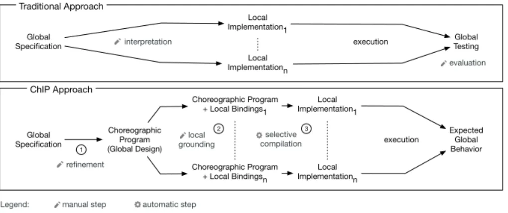
Global Specification Choreographic Program (Global Design) Choreographic Program + Local Bindings1 Choreographic Program + Local Bindingsn Local Implementation1 Local Implementationn Expected Global Behavior refinement local grounding execution selective compilation ChIP Approach Global Specification Local Implementation1 Local Implementationn Global Testing execution interpretation Traditional Approach evaluation 1 2 3
manual step automatic step Legend:
Fig. 1. Schemes of the traditional and the ChIP approaches.
discrepancies among disparate technology stacks. The interest in this scenario has recently increased thanks to a new revenue model, called API Economy [6]. Adopting API Economy, many companies, among which Google, Facebook, eBay, and Sabre, started to sell to other organizations the access (under subscription, license, etc.) to their internal services. Although API Economy founds its model on integration, its practice is left to unstructured glue programming.
Both centralized and distributed glue programs are used [7]. In the centralized approach a unique glue program interacts with all the integrated systems. This entails all classical drawbacks of centralized systems in terms of scalability and reliability. Furthermore, this centralized connector has full access to the integrated functionalities, yet it resides on the premises of one of the involved organizations (or on third-party premises), hence issues of trust among organizations arise.
In the distributed approach, each stakeholder provides one or more connectors. Each connector interacts with both i ) other connectors, to realize the intended logic of integration and ii ) a set of local functionalities, which may not be accessi-ble by the other connectors. In essence, each connector acts as an adapter for other glue programs. Each connector runs on the premises of one of the collaborating partners, providing a controlled access towards one or more of its resources. The traditional approach in developing distributed glue programs [8] is represented in Figure 1, top half. First, a global specification of the integration is agreed upon by the stakeholders, using (frequently informal or semi-formal) notations such as Message Sequence Charts [9] (MSC), UML Sequence Diagrams [10] or BPMN choreographies [11]. The development team of each partner uses such a global specification as a reference to build the local implementation of the glue programs. Finally, the network of glue programs is executed and the emerging behavior is contrasted against the global specification.
The main drawback of this approach lies in the huge information gap be-tween a global specification and its distributed implementation. Given a shared global specification, the development team of each partner independently fills
the missing pieces of information, possibly taking contrasting decisions. These misalignments lead to incompatibilities among glue programs, which in turn result in misbehaviors and system blocks [12]. In addition, the resulting network of glue programs is brittle and difficult to evolve.
Contribution. To address these issues, we propose a structured integration process, called ChIP (Choreographic Integration Process). The bottom half of Figure 1 outlines the steps prescribed by ChIP, detailed in Section 3. Here, to briefly introduce the ideas behind ChIP, we comment the two main artifacts built during the process. The first one to be produced is a global specification of the integrated system. It is intended for domain experts and gives a very abstract view of the system, omitting many details of the actual implementation. ChIP does not impose the use of a particular modeling notation to define the global specification. Examples of notation for global specification that we consider suitable within ChIP are MSCs, BPMN choreographies, and UML Sequence Diagrams. The second artifact is a global design, refinement of the global specification. The global design is the focal point of ChIP: it must be defined in a choreographic programming language [13,14,15] that i ) supports the compilation of a choreography into a set of connectors that faithfully implement the designed global interactions—so that local connectors can be automatically generated from a global design—and ii ) it is able to express at the global level when and how a given local connector invokes a local functionality, so that the global design describes the whole integration within a unique artifact.
Structure of the paper. Section 2 discusses the positioning of the ChIP approach in the literature. Section 3 outlines ChIP, while Section 4 applies it to a real-world pilot from the EU EIT Digital project SMAll, aimed at integrating functionalities from the Emilia Romagna (Italy) regional government, University of Bologna, and a transport company. In this presentation we decided to use UML Sequence Diagrams to define the global specification and the AIOCJ choreographic pro-gramming language [16,17] for the global design. Section 5 clarifies how to exploit tools like AIOCJ within ChIP. Section 6 discusses the impact of ChIP on the evolution of integration solutions. Section 7 presents final remarks and future developments.
2
Related Work
Information systems that evolve over pre-existing legacy applications have always been a concern of system integration [18]. However, no definitive solution exists.
Choreographic programming, that is the use of choreographies to generate executable code, as advocated in ChIP, is quite recent and the literature on the topic is extremely limited [19,20,21,22,13,14,15]. Notably, among the approaches above, only [15], on which ChIP is built, provides a way of describing interac-tions with systems external to the choreographic program. The present paper complements the technical results and the tool presented in [15] by proposing
a software development process where such results and tool are exploited. The other approaches listed above, since they cannot represent interactions with external systems, can be used to generate distributed systems but not distributed integrations.
More in general, choreographic programming can be framed in the setting of choreographic descriptions of communicating systems. Choreographies have been introduced in the area of business process management to support the description of business-to-business collaborations [23]. While the idea of the approach is not far from ours, they consider models such as Petri Nets that are more abstract and have less emphasis on communication than choreographic programming. Also they do not specifically target integrations of pre-existing systems.
More recently, approaches sharing our communication-centric view have appeared. Broadly, ChIP can be classified as a top-down approach: the integration is specified and designed at the global level, declaring which functionalities it will integrate and the logic of the integration. Locally, deployment information is added to link the desired functionalities to actual services providing them. Finally, local code for the connectors is automatically generated.
Other approaches we are aware of are not top-down, but mixed: they assume both a choreographic specification and an existing running integration. We divide them into two categories:
– Type-based approaches rely on multiparty session types [24], cannot be directly used to implement connectors but are a non-invasive solution to statically check [25] or dynamically monitor [26] the correctness of the integrations. Among the various approaches, Compositional Choreographies [27], which however have never been implemented neither applied to system integration, would be the closest to ours: thanks to compositionality, Compositional Choreographies describe both the glue connectors and the systems to be integrated, as we do.
– Model driven approaches, such as [28,29] concentrate on realizability enforce-ment. Namely, they are used to build coordination delegates that limit the possible interactions between integrated services, avoiding undesired com-munication patterns. However, they cannot provide added behavior, hence limiting the forms of integration that can be specified.
In principle, instead of choreographic programs, one could use other formal coordination languages able to describe a global system and that support code generation, such as BIP [30], Reo [31], Dynamic Condition Response Graphs [32] or Let’s Dance [33]. We choose choreographic programs since they are closer to UML Sequence Diagrams and BPMN choreographies, which are frequently used as starting point of the development process. Among those approaches, to the best of our knowledge, BIP is the only one that has a description of its intended use in the software development process from a software engineering perspective [30], as done here for choreographic programs. The two approaches are quite different in practice since BIP is a declarative model, while choreographic programs are operational descriptions.
3
A Choreographic Integration Process: Outline
In this section we give a general definition of the three-step process that charac-terizes ChIP, as outlined in the bottom half of Figure 1. In the next section we will apply ChIP to a real-world integration project.
The main innovation of ChIP consists in filling the information gap between global specification and local implementations present in the traditional approach, using a three-step structured process:
1 a collective refinement process that, from an abstract global specification, leads to a global design expressed as a choreographic program. The obtained choreographic program formally defines the expected global behavior and clarifies which tasks are delegated to which stakeholder. The first step of ChIP is highly non trivial, nevertheless it provides a well-defined, limited task to users: defining an agreed global design of the logic of the integrated system. This contrasts with the unstructured, “open” task of the classical case, where from a global specification users should come up with their local implementations. In the ChIP approach, this step considers descriptions of the system from a global perspective, hence issues related to synchronization and distribution can still be abstracted away. The design is agreed upon by the participants and includes the whole logic of integration.
2 a local grounding separately performed by each stakeholder, which links the functionalities that each participant promised to deliver to actual resources in its IT system. Hence, this phase is straightforward. The information on which internal resources are used needs not to be shared with the other stakeholders: the access to these functionalities is provided via the local glue programs, which are under the control of the stakeholder and which run in its own system.
3 the fully automatic generation of the local connectors from the grounded global design (i.e., the grounded choreographic program). Making this step automatic is far from trivial, but it is tackled relying on well-known techniques called choreographic programming [13,14,15], endpoint projection [25] or choreography realizability [22]. Here, in particular, we exploit for this step the notion of endpoint projection described in [15], which is implemented in the AIOCJ tool [16,17]. Notably, the global behavior emerging from the execution of the glue programs is compliant with the global design by construction: synchronization and distribution issues are automatically managed. This avoids misalignments among the local implementations; a renowned problem of the traditional approach.
Remarkably, the process proposed in ChIP eases also the evolution of integration solutions. For example, it is relatively simple to take a choreographic program belonging to a previous ChIP iteration and to modify it by including new stake-holders and/or changing the logic of interaction. In step 2 , users can possibly reuse local groundings defined in the previous iteration. In step 3 users either obtain a connector that replaces an existing one or a completely new one, useful
Tracker by University Bus Agency Regional Government
Tracked line
Line schedule
loop (until schedule has next stop)
Current bus position Calculated delay
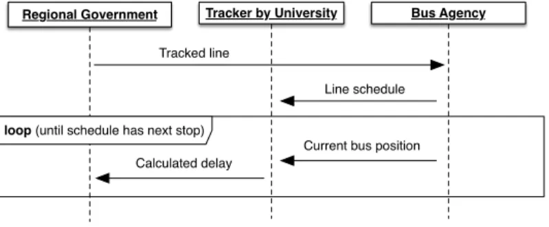
Fig. 2. Sequence Diagram of the Pilot.
for integrating new functionalities. We further discuss the impact of ChIP on system evolution in Section 6.
4
A Choreographic Integration Process at Work
Running Example. We illustrate ChIP via a real-world pilot developed within the recent European EIT Digital project SMAll4 The focus of SMAll is the creation of the namesake platform5 [34] aimed at marketing functionalities for transportation owned, managed, and offered by diverse transport operators. The revenue model underlying the SMAll platform is based on the API Economy, where players whose core business is not that of information systems (e.g., in the context of SMAll, bus/train agencies, taxi associations) can publish and sell their functionalities within a global market. Some pilots have been developed as part of the SMAll project. Each pilot integrates pre-existing services, owned by diverse organizations, to provide new applications.
Below we refer to one of these pilots as a real-world example of application of the ChIP approach. The considered pilot is called BusCheck, it was commissioned by the Department of Transportation of the government of the Emilia-Romagna (ER) region (Italy) to the University of Bologna, and it is aimed at recording
and displaying the punctuality of buses in Bologna county.
Global Specification. Both the traditional approach and ChIP start with an informal or semi-formal description of the intended global behavior, such as the UML Sequence Diagram in Figure 2. In this phase the intended behavior is described at the highest level of abstraction by the domain experts of the different stakeholders. Such a description is agreed among the different stakeholders and constitutes the starting point of the integration.
4 Project description:
https://forumvirium.fi/en/small-develops-mobility-as-a-service/
5 Deployable platform: https://hub.docker.com/u/smallproject/
The collaborating partners in BusCheck are the ER Government, the Univer-sity of Bologna, and the local Bus Agency. The flow of integration starts from the ER Government, which issues the tracking of the next ride of a specific line to the Bus Agency. Then, the Bus Agency delivers to the University the schedule of the requested ride. Finally, until the tracked ride reaches the final stop, the Bus Agency sends the current bus position to the University, which computes the delay and sends it to the Regional Government.
1 Global Specification Refinement. In this first step the abstract global specification is refined to obtain a global design. This phase ends when the global design is complete and agreed upon by the different stakeholders. Given the technical background necessary at this stage, we assume the collaboration of personnel from each stakeholder IT department. Following ChIP, IT personnel uses a full-fledged, high-level programming language, implementing the choreographic programming paradigm [14,15], to formalize the integration design. Choreographic programs are the key feature of the ChIP approach, since they provide two benefits: 1. they preserve a global view over the integrated systems, hence they are
conceptually close to the original global specification, and
2. they already contain all the logic of the integration in a formal notation, hence they can later on be used to automatically generate the local code of each glue program, without the need for any additional behavioral information. This is particularly relevant since the addition of further behavioral information at the local level may create inconsistencies.
At this stage, choreographic programs are artifacts that support the transition from an informal global specification to a formal global design. The precise methodology used for this refinement step is not key in ChIP, provided that at the end of the phase the global design is formalized as a choreographic program. However, we advocate for this step an iterative approach, where details are added to the specification and technical decisions are recorded. Notably, at some point during the refinement, one should move from the specification notation (UML Sequence Diagram in this example) to the choreographic program notation. While a complete description of the step goes beyond the scope of the present paper, we remark that choreographic programs easily capture the information contained in UML Sequence Diagrams, yet require more information to be added. We will show this in detail in the case of our pilot. Further refinement steps can be performed both before, at the level of UML Sequence Diagram, and after, at the level of choreographic program. In our running example, we first translate the UML Sequence Diagram into the choreographic specification in Listing 1.1, where we use question marks as placeholders for missing information.
Notably, the communications represented in the UML Sequence Diagram are directly mapped into interactions in the choreographic specification. An interaction represents a full message exchange, where one participant sends a message and another participant receives it, storing it in one of its local variables. For instance passPosition: BusAgency(pos) -> Tracker(pos) represents the interaction between theBusAgency and theTrackerprovided by the University of Bologna to send the information on the position of the bus. We remark here
1 s e t L i n e : Government( line ) -> BusAgency( line );
2 p a s s S c h e d u l e : BusAgency( shd ) -> Tracker( shd );
3 w hil e( h a s N e x t )@? {
4 p a s s P o s i t i o n : BusAgency( pos ) -> Tracker( pos );
5 s t o r e D e l a y : Tracker( d ela y ) -> Government( d ela y )
6 }
Listing 1.1. Choreographic specification of the BusCheck pilot, first version.
that variables are local, hence the two occurrences of pos in the interaction refer to distinct variables: the left one is local to theBusAgency connector and the right one belongs to theTracker.
Commenting the choreographic specification in Listing 1.1, the question mark at line 3 is a placeholder for the name of the participant that coordinates the distributedwhileloop, i.e., the one that at each iteration evaluates the condition hasNext and coordinates whether the participants involved in the loop shall enter another iteration or exit. Beyond missing the information replaced by the question mark, the choreographic specification also misses all the computational information regarding which local functionalities are needed and how values are computed. This is why we still call it a choreographic specification and not a choreographic design.
However, before adding the missing details, the ER Government decides to refine the system representation by splitting its behavior between two connectors: an Administrator, representing the official requesting the tracking of a certain line, and aDatabaseConnector which stores the data on delays of the tracked line for later analysis (the latter not in the scope of the pilot). The resulting choreographic specification is represented in Listing 1.2. Note the new interaction at line 1, which represents a communication internal to the ER Government, exposed by the refinement step (the interaction is composed with the one at line 3 using the parallel operator |, which models the fork-and-join pattern). All the stakeholders need to approve this refined specification, since all the choreographic specifications are shared documents.
Finally, the stakeholders prepare and agree on a concrete version of the choreographic description, containing all the behavioral information: only at this stage we can call it a global design. The main novelty in the global design is that it describes which functionalities need to be invoked, and when. For instance, with the invocation shd@BusAgency = getSchedule( line ) theBusAgencypromises to deliver a functionality named getSchedule, that, given a line, returns its schedule. At this stage, the semantics of the functionality is undefined. However, the invocation already specifies which variables the functionality will use (line) and where the result will be stored (shd).
Summarizing, the main ingredients of a choreographic program are inter-actions, describing the expected communications among the glue programs, and placeholders for invocations of local functionalities. Interactions and local functionalities can be composed using an arbitrarily complex logic, including
1 { s e t L i n e : Admin( line ) -> DatabaseConnector( line )
2 |
3 s e t L i n e : Admin( line ) -> BusAgency( line )
4 };
5 p a s s S c h e d u l e : BusAgency( shd ) -> Tracker( shd );
6 w hil e( h a s N e x t )@? {
7 p a s s P o s i t i o n : BusAgency( pos ) -> Tracker( pos );
8 s t o r e D e l a y : Tracker( d ela y ) -> DatabaseConnector( d ela y );
9 }
Listing 1.2. Choreographic specification of the BusCheck pilot, refined.
conditionals, loops, etc. The resulting global design of our running example is represented in Listing 1.3, and described in detail below.
A condition for the refinement phase to be finished is that the resulting global design is realizable [22] (or connected, according to the terminology in [15]), i.e., it contains enough information on how the interaction is coordinated. This can be checked automatically using the approaches in [22,15]. If this is not the case, refinement should continue by adding the missing information. This aspect of refinement has been described in [35,36].
Global Design. The global design is a choreographic program [14,15] defining the expected behavior of the integration. Here, in particular, we use a variant of the AIOCJ [16,17] choreographic programming language.
At lines 1–5 the partners declare the location where their local connectors will be reachable. This is the only deployment information that the partners have to share and, as a consequence, it is inserted in the global design.
Lines 8–11 compose with operator|two interactions in parallel: theAdmin is-trator sends to both the DatabaseConnector and theBusAgency the bus line that the official wants to track (inserted at line 7) in a specific execution of the program. Since the composition is within braces, the system proceeds to line 12 only after both messages are stored in their respective local variables line. At line 12, theBusAgency retrieves the schedule of the tracked bus line, using the functionality getSchedule, and passes it to theTracker(line 13).
Finally, lines 15–23 describe a loop among theTracker, theBusAgency, and theDatabaseConnector. We recall the description of Listing 1.1, where a question mark indicates the need to define which participant should evaluate the condition of the loop and coordinate the other participants in its body. In the refined global design the coordinator of the loop is theTracker and the condition it evaluates depends on the result of the invocation of the hasN extStop functionality. The hasN extStop functionality is also used to pace the loop: when invoked to check the presence of another stop, it also waits until it is time to poll again the position of the tracked line (e.g., when the bus is expected to be approaching a stop).
Inside the loop, at each iteration, theBusAgency retrieves the position of the current bus on the observed bus line (line 16) and passes it to the Tracker
(line 17). Then, at line 18, the Trackerinvokes function calculateDelay. At line 19, the calculated delay is sent to the DatabaseConnector. Finally, two external
1 l o c a t i o n s {
2 Admin: " reg - gov . org :80/ B u s C h e c k A d m i n "
3 DatabaseConnector: " reg - gov . org :80/ B u s C h e c k D B "
4 Tracker: " u n i v e r s i t y . edu :80/ T r a c k e r "
5 BusAgency: " bus - a g e n c y . com :80/ B u s C h e c k " }
6
7 line@Admin = getInput(" I n s e r t line to t rac k ");
8 { s e t L i n e : Admin( line ) -> DatabaseConnector( line )
9 |
10 s e t L i n e : Admin( line ) -> BusAgency( line )
11 };
12 shd@BusAgency = getSchedule( line );
13 p a s s S c h e d u l e : BusAgency( shd ) -> Tracker( shd );
14 h a s N e x t@Tracker = hasN extStop( shd );
15 w hil e( h a s N e x t )@Tracker {
16 pos@BusAgency = getP osition( line );
17 p a s s P o s i t i o n : BusAgency( pos ) -> Tracker( pos );
18 d ela y@Tracker = calculateDelay( shd , pos );
19 s t o r e D e l a y : Tracker( d ela y ) -> DatabaseConnector( d ela y );
20 { res@DatabaseConnector = insertDelay( line , delay )
21 |
22 h a s N e x t@Tracker = hasN extStop( shd )
23 } }
Listing 1.3. Global design of the BusCheck pilot.
functionalities are invoked in parallel: theDatabaseConnectorinserts the delay for the observed bus line in the database (line 23) and the Tracker invokes functionality hasN extStop to check if and when a new iteration has to start.
Note that our choreographic program does not detail how to perform dis-tributed synchronizations. For instance, the loop at lines 15-23 involves different distributed connectors, but it is unspecified how to ensure that all the connec-tors follow the prescribed behavior, i.e., looping or exiting when the Tracker
decides so. This level of abstraction can be kept thanks to the selective compi-lation (described later), which automatically generates correct message-based synchronization algorithms, as detailed in [15].
2 Local Grounding. The global design is the last document agreed upon by all the stakeholders. The local grounding is performed by each participant in isolation. For instance, the Bus Agency IT personnel grounds the global design by providing the binding for its internal functionalities getSchedule and getP osition. These functionalities are only invoked by the local connector, which acts as an intermediary by providing to the other participants access to the local functional-ities as prescribed by the global design. Concretely, the deployment information for the Bus Agency is represented in Listing 1.4. Thedeploymentdeclares the internal address where each functionality is available, possibly specifying the communication medium and the data protocol to be used. For instance, at line 2, the prefix"socket://" specifies the usage of TCP/IP as medium while SOAP specifies the used data protocol. This flexibility on communication media and
1 d e p l o y m e n t {
2 getSchedule from " s o c k e t :// i n t r a n e t . s c h d l s : 800 0 " with SOAP
3 getP osition from " s o c k e t :// i n t r a n e t . GPS : 800 1 " with HTTP }
Listing 1.4. Deployment for the Bus Agency.
data protocol is fundamental to enable the integration of disparate preexisting functionalities.
3 Selective Compilation. Finally, at this stage, the Bus Agency has specified all the information needed to automatically generate its local connector. The generation of the connector for theBusAgencytakes the global design and the deployment information for theBusAgencyand produces an executable program implementing the local logic of the connector.
Selective compilation hides most of the complexity of developing distributed glue connectors that interact with each other, without a central coordinator. This step is far from trivial, however it is well understood: it corresponds to the notion of endpoint projection in choreographic programming [13,15]. In particular, AIOCJ programs can be projected [15] by automatically creating web services in the Jolie [37,38] language.
As an illustrative example, we report in Figure 3 an excerpt of the pseudo-code of the compiled connectors of theBusAgency, theDatabaseConnector, and the
Tracker6. The pseudo-code shows the result of the selective compilation of lines 14-23 in Listing 1.3. In the reported code, programs communicate throughsend
andrecv(short for “receive”) instructions. External functionalities are invoked through the call instruction. In addition to the communications created by interactions in the global design, we also show the auxiliary communications used to ensure a coordinated execution of the while loop. Auxiliary communications are prefixed with an underscore “_”, e.g., _wG1 (standing for while guard) and _wE1(standing for while end) indicate the auxiliary communications used by the
Trackerand theBusAgencyto coordinate within the distributed loop.
Expected Global Behavior. A main feature of ChIP is that no behavior is defined by the single stakeholder: all the behavior is described globally and agreed by all the stakeholders. This avoids the possibility that different stakeholders take contrasting decisions.
Furthermore, the generation of local connectors from the choreographic pro-gram has been proved correct in [15], hence no error can be introduced in this step. Of course, the stakeholders may agree on a wrong integration behavior. However, in choreographic programs, interactions are represented as atomic entities, hence it is syntactically impossible to express deadlocks and races on communications, avoiding by design the presence of such infamous bugs in the agreed integration behavior and, as a consequence, in the generated distributed network of connectors.
6
The compiled connectors are available at http://www.cs.unibo.it/projects/jolie/ aiocj examples/ChIP example/ChIP example.zip.
1 recv _wG1 ( h a s N e x t ) from Tracker;
2 wh ile( h a s N e x t ){
3 pos = call getP osition( line );
4 send p a s s P o s i t i o n ( pos ) to Tracker;
5 send _wE1 () to Tracker;
6 recv _wG1 ( h a s N e x t ) from Tracker
7 }
BusAgency
1 recv _wG2 ( h a s N e x t ) from Tracker;
2 wh ile( h a s N e x t ){
3 recv s t o r e D e l a y ( de lay ) from Tracker;
4 res = call insertDelay( line , delay );
5 send _wE2 () to Tracker;
6 recv _wG2 ( h a s N e x t ) from Tracker
7 }
DatabaseConnector
1 h a s N e x t = call hasN extStop( shd );
2 send _wG1 ( h a s N e x t ) to BusAgency;
3 send _wG2 ( h a s N e x t ) to DatabaseConnector;
4 wh ile ( h a s N e x t ){
5 recv p a s s P o s i t i o n ( pos ) from BusAgency;
6 de lay = call calculateDelay( shd , pos );
7 send s t o r e D e l a y ( de lay ) to DatabaseConnector;
8 recv _wE1 () from BusAgency;
9 recv _wE2 () from DatabaseConnector;
10 h a s N e x t = call hasN extStop( shd );
11 send _wG1 ( h a s N e x t ) to BusAgency;
12 send _wG2 ( h a s N e x t ) to DatabaseConnector
13 }
Tracker
Fig. 3. From top-left to bottom, an excerpt (lines 14–23 of Listing 1.3) of the compiled connectors of theBusAgency, theDatabaseConnector, and theTracker.
5
A Choreographic Integration Process: Tool Support
The ideas described in the previous sections are quite general, relying on key features of global specification languages and choreographic programs. The running example instantiated these ideas using UML Sequence Diagrams and the AIOCJ choreographic programming language. We do not describe support for UML Sequence Diagrams since there are many tools that support them. On the contrary, we dedicate this section to describe AIOCJ, which is less known yet it is fundamental for the approach. Furthermore, it has been adapted to support ChIP. While referring to [17,15] for a detailed description of AIOCJ, we clarify here why it is suitable for ChIP, and how it has been updated to support it. AIOCJ has been created to program adaptive applications [17], but the main reason why we build on it is that it supports not only choreographic programming and realizability checking (as done, for instance, by Chor [13] or Scribble [39]), but also interaction with external services. This last feature is fundamental to speak about integration, and, as far as we know, AIOCJ is currently the only choreographic language providing it. AIOCJ generates code for the local connectors in the Jolie [38,37] programming language. A relevant feature that AIOCJ inherits from Jolie is the possibility of supporting multiple communication media (TCP/IP sockets, Bluetooth L2CAP, Java RMI, Unix local sockets) and data protocols (HTTP, SOAP, . . . ) in a uniform way. This is convenient to integrate heterogeneous functionalities, as done, e.g., in Listing 1.4.
AIOCJ takes a choreographic program and generates code for all connectors at once, hence it needs full deployment information. This is not suitable for ChIP, where each stakeholder i ) generates its own connectors and ii ) can provide only deployment information on the other connectors and its local functionalities—i.e., it ignores the deployment of functionalities owned by the other stakeholders. Thus, we have extended AIOCJ with support for separate compilation: one can select which connectors to generate, and only the needed deployment information is required. Like AIOCJ, its extension with support for separate compilation is released as an open-source project7.
We currently do not provide tool support for step 1 of ChIP. Step 2 does not require any tool support: deployment information and choreographic program can simply be concatenated. Finally, step 3 can be performed using AIOCJ with separate compilation. To this end, both the choreographic program and the deployment information need to fit AIOCJ syntax, reported in [16].
Note that the original version of AIOCJ can be used for testing: if full infor-mation for a local deployment is provided (and stubs for required functionalities are in place), AIOCJ will provide a fully working local network of connectors, that can be immediately tested to check whether the behavior is as expected. Changing the deployment information does not change the behavior (provided that required functionalities are available), hence this local test is relevant.
6
Evolution of Integrated Systems
Another important aspect of system integration, besides the design of new solu-tions, is the evolution of existing ones [40]. On the one hand, the rigidity of the integration imposes constraints on the network topology and the functionalities of the internal system of each stakeholder; on the other hand, each stakeholder strives to evolve its internal system independently, adapting it to environmental changes and newly-adopted business policies. Finally, integration solutions may also need to adapt to mirror changes in business relationships between the stake-holders, e.g., when some stakeholders leave or join the partnership. Managing these elements of software evolution is an essential aspect of software manage-ment, strongly supported by modern engineering approaches such as continuous delivery [41] and continuous deployment [42]. ChIP can be easily integrated into such modern approaches, offering a structured process for system design and evolution. Concretely, in ChIP, the generation of connectors is already automatic, hence automation can go directly from the global design to the deployment. Furthermore, the artifacts developed during the ChIP process, namely the global specification, the global design, and the local bindings, can be reused and updated during evolution. More in detail, in ChIP, updates to the integration are either done from the design step and/or locally, at the step of local grounding (e.g., starting from a pre-existing global design and reiterating from step 2 ).
As expected, reiterating ChIP from step 2 concerns only the local resources of single stakeholders and it is transparent to the other stakeholders. Contrarily,
7
Tracker by University Bus Agency Regional Government
Tracked line
alternative (if signed data is valid)
Line schedule
Signed current bus position
loop (until schedule has next stop)
Calculated delay
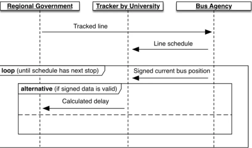
Fig. 4. Evolved Sequence Diagram of the Pilot.
changes at the design level may influence many participants in the integration. In this case, partners can decide to update the integration either from the level of global specification or from that of global design. Such a decision is based on the visibility of the modifications. If the update regards only some technical details that are abstracted away in the global specification, partners can just have their IT personnel agree on a new version of the pre-existing global design, automatically generating the new connectors that implement the updated design (to replace the previous ones). On the contrary, if the update is visible at the level of the global specification, the domain experts of each stakeholder should reiterate over the whole ChIP process, first agreeing upon an updated version of the pre-existing global specification and then revising steps 1 , 2 , and 3 to obtain the updated integration solution.
We contrast this situation with what would be needed in the traditional integration process: the global specification is updated — provided that the change is relevant enough to be visible at the specification level — and then developers of each stakeholder need to update their local connectors accordingly. There, understanding which local changes are needed to enable a new desired global behavior is far from trivial, it requires good coordination among the involved teams, and it is prone to misbehaviors.
Example of System Evolution in ChIP. To illustrate how the ChIP process simplifies the evolution of existing integration solutions, we consider our running example and assume that, due to administrative data-provenance regulations, the Bus Agency must digitally sign each bus position sent to the University, while the University is asked to discard any unsigned data it receives.
According to the evolution process described in the previous paragraphs, first the stakeholders should agree upon a revised version of the global specification. To exemplify this, we report in Figure 4 a possible revision of the UML Sequence Diagram in Figure 2. In Figure 4 in the loop fragment the Bus Agency sends
15 w hil e( h a s N e x t )@Tracker {
16 pos@BusAgency = getP osition( line );
17 s i g n e d _ p o s@BusAgency = sign( pos );
18 p a s s P o s i t i o n : BusAgency( s i g n e d _ p o s ) -> Tracker( pos );
19 v ali d@Tracker = validate( pos );
20 if( v ali d )@T r a c k e r {
21 d ela y@Tracker = calculateDelay( shd , pos );
22 s t o r e D e l a y : Tracker( d ela y ) -> DatabaseConnector( d ela y );
23 _@DatabaseConnector = insertDelay( line , delay )
24 };
25 h a s N e x t@Tracker = hasN extStop( shd )
26 }
Listing 1.5. Global design of the updated BusCheck pilot.
a message labeled “signed current bus position” to the University. The data, if validated, is used to calculate the delay sent to the Regional Government. In the other case—the empty lane in the alternative fragment in Figure 4—the received data is not used and therefore discarded.
Once the updated global specification is agreed upon by all the stakeholders, they can proceed with step 1 by just modifying the second half of the global design in Listing 1.3. We report in Listing 1.5 the updated code of Listing 1.3. The most relevant changes are: i ) at line 17 theBusAgencyinvokes a new functionality to sign the retrieved position of the current bus, ii ) at line 19 theTrackerinvokes a new functionality to validate the data sent by theBusAgency, and iii ) at lines 20-24 theTrakerdecides, based on the result of the validation, whether to use the data for delay calculation or to discard it and proceed with the next iteration.
After agreeing upon the global design in Listing 1.5, the stakeholders proceed to the individual local grounding (as of step 2 ). In the example, only the
BusAgencyand theTrackerhave to modify their pre-existing groundings, respec-tively defining the location of functionalities sign and validate. Following step 3 , each partner automatically generates its own updated connectors. Finally, to start the updated version of the integration, all the partners have to terminate the previously deployed connectors and deploy their respective replacements.
Dynamic Evolution. As exemplified above (as well as in the traditional approach), when updating a pre-existing system, the stakeholders have to shut-down the deployed connectors, replace them, and restart the whole integrated architecture. In many application contexts these downtimes are acceptable, how-ever when the integrated systems need to be always online, it is imperative to avoid or at least minimize these downtimes.
Shutdown can be avoided by resorting to live update techniques, such as the ones described in [43]. However, as shown in [43], only a few of these techniques support the live update of distributed systems. Indeed, while the centralized case entails the update of just one program, in the distributed case a protocol must be in place to coordinate the update of the distributed components, avoiding
unexpected behaviors that may arise when updated components interact with components which have not been updated yet.
Notably, AIOCJ provides one of the few techniques for live updates of dis-tributed systems, that is of the disdis-tributed connectors it generates. We refer to [15] for a full description of the technique, since it is out of the scope of the present paper. Essentially, selected parts of the choreographic program can be replaced by new choreographic program fragments at runtime thanks to AIOCJ runtime support. As proved in [15], AIOCJ guarantees correctness of the behavior after the update, and avoids unexpected behaviors while the update is applied.
7
Conclusion
We presented ChIP, a novel integration process suited for distributed, cross-organizational scenarios. The main highlight of ChIP is that it provides a struc-tured way to refine abstract global specifications (e.g., UML Sequence Diagrams) into corresponding concrete implementations. The refinement process relies on choreographic programs to represent a global design agreed upon by all partners of the integration. The global design is used by each stakeholder to selectively compile its own set of executable connectors.
In ChIP, choreographies provide the main benefits of i ) enabling a simpler and less error-prone refinement process, since they are closer to the high-level global specifications with respect to low-level implementations; ii ) structuring how the integrated functionalities of each partner are accessed, without disclosing relevant information, like the internal topology of partners (which can even change dynamically, provided it preserves the interface expected by connectors); iii ) supporting a correctness-by-construction approach that guarantees the faithful implementation of the agreed global design, also avoiding hard-to-debug mis-behaviors such as deadlocks; iv ) simplifying the evolution of the system, thus matching nicely continuous delivery and continuous deployment approaches.
While ChIP provides an innovative framework for integration, many aspects need further study. The global refinement phase should be fully specified (taking into account the different possible notations for the global specification) and equipped with suitable tool support. Integration should also be type safe, by declaring types both for variables in the global design and for external function-alities, relying, e.g., on XML Schema [44] type system. Other relevant issues include how to deal with exceptional behavior, transactions, large and complex data structures, security and non-functional properties. While a detailed study of each of these topics would be long and challenging, we deem ChIP able to help dealing with them. The broad idea is that desired behaviors, e.g., transactional or security properties, can be specified at the global level and then advanced projections ensure that specifications are matched by the running system. An approach along these lines for security properties is described in [45].
References
1. D. Garlan, R. Allen, and J. Ockerbloom, “Architectural mismatch or why it’s hard to build systems out of existing parts,” in ICSE, pp. 179–185, ACM/IEEE, 1995. 2. W. He and L. Da Xu, “Integration of distributed enterprise applications: A survey,”
IEEE Trans. Ind. Informat., vol. 10, no. 1, pp. 35–42, 2014.
3. D. Russo et al., “Software quality concerns in the Italian bank sector: The emergence of a meta-quality dimension,” in ICSE, pp. 63–72, ACM/IEEE, 2017.
4. L. M. Hitt, D. Wu, and X. Zhou, “Investment in enterprise resource planning: Business impact and productivity measures,” JMIS, vol. 19, no. 1, pp. 71–98, 2002. 5. A. Endres and H. D. Rombach, A handbook of software and systems engineering:
Empirical observations, laws, and theories. Pearson Education, 2003.
6. P. C. Evans and R. C. Basole, “Revealing the API ecosystem and enterprise strategy via visual analytics,” Communications of the ACM, vol. 59, no. 2, pp. 26–28, 2016. 7. S. Jongmans and F. Arbab, “Global consensus through local synchronization: A
formal basis for partially-distributed coordination,” SCP, vol. 115, 2016.
8. W. He and L. Da Xu, “Integration of distributed enterprise applications: A survey,” IEEE Transactions on Industrial Informatics, vol. 10, no. 1, pp. 35–42, 2014. 9. International Telecommunication Union, “Message Sequence Chart (MSC),” Series
Z: Languages and General Software Aspects for Telecommunication Systems, 2011. 10. G. Booch, The unified modeling language user guide. Pearson Education India,
2005.
11. T. Allweyer, BPMN 2.0: introduction to the standard for business process modeling. BoD–Books on Demand, 2016.
12. T. Leesatapornwongsa et al., “Taxdc: A taxonomy of non-deterministic concurrency bugs in datacenter distributed systems,” in ACM SIGPLAN Notices, vol. 51(4), pp. 517–530, ACM, 2016.
13. M. Carbone and F. Montesi, “Deadlock-freedom-by-design: multiparty asynchronous global programming,” in POPL, pp. 263–274, ACM, 2013.
14. F. Montesi, “Kickstarting choreographic programming,” in WS–FM, LNCS, pp. 3– 10, Springer, 2014.
15. M. Dalla Preda et al., “Dynamic choreographies: Theory and implementation,” Logical Methods in Computer Science, vol. 13, no. 2, 2017.
16. “AIOCJ website.” http://www.cs.unibo.it/projects/jolie/aiocj.html.
17. M. Dalla Preda et al., “AIOCJ: A choreographic framework for safe adaptive distributed applications,” in SLE, LNCS, pp. 161–170, Springer, 2014.
18. W. Hasselbring, “Information system integration,” Communications of the ACM, vol. 43, no. 6, pp. 32–38, 2000.
19. G. Decker, J. M. Zaha, and M. Dumas, “Execution semantics for service choreogra-phies,” in WS-FM, vol. 4184 of LNCS, pp. 163–177, Springer, 2006.
20. Z. Qiu, X. Zhao, C. Cai, and H. Yang, “Towards the theoretical foundation of choreography,” in WWW, pp. 973–982, ACM, 2007.
21. S. McIlvenna, M. Dumas, and M. T. Wynn, “Synthesis of orchestrators from service choreographies,” in APCCM, vol. 96 of CRPIT, pp. 129–138, Australian Computer Society, 2009.
22. S. Basu, T. Bultan, and M. Ouederni, “Deciding choreography realizability,” in POPL, pp. 191–202, ACM, 2012.
23. W. M. van der Aalst and M. Weske, “The p2p approach to interorganizational workflows,” in CAiSE, pp. 140–156, Springer, 2001.
24. H. H¨uttel et al., “Foundations of session types and behavioural contracts,” ACM Computing Surveys, vol. 49, no. 1, p. 3, 2016.
25. K. Honda, N. Yoshida, and M. Carbone, “Multiparty asynchronous session types,” J. ACM, vol. 63, no. 1, pp. 9:1–9:67, 2016.
26. L. Bocchi et al., “Monitoring networks through multiparty session types,” Theor. Comput. Sci., vol. 669, pp. 33–58, 2017.
27. F. Montesi and N. Yoshida, “Compositional choreographies,” in CONCUR, vol. 8052 of LNCS, pp. 425–439, Springer, 2013.
28. M. Autili, P. Inverardi, and M. Tivoli, “Choreos: large scale choreographies for the future internet,” in CSMR-WCRE, pp. 391–394, IEEE, 2014.
29. M. Autili et al., “A model-based synthesis process for choreography realizability enforcement,” in FASE, LNCS, pp. 37–52, Springer, 2013.
30. A. Basu et al., “Rigorous component-based system design using the BIP framework,” IEEE Software, vol. 28, no. 3, pp. 41–48, 2011.
31. F. Arbab, “Reo: a channel-based coordination model for component composition,” MSCS, vol. 14, no. 3, pp. 329–366, 2004.
32. T. T. Hildebrandt, R. R. Mukkamala, and T. Slaats, “Nested dynamic condition response graphs,” in FSEN, vol. 7141 of LNCS, pp. 343–350, Springer, 2011. 33. J. M. Zaha and other, “Let’s dance: A language for service behavior modeling,” in
OTM Confederated International Conferences, pp. 145–162, Springer, 2006. 34. F. Callegati et al., “Smart mobility for all: A global federated market for
mobility-as-a-service operators,” in ITSC, pp. 1–8, IEEE, 2017.
35. I. Lanese, F. Montesi, and G. Zavattaro, “Amending choreographies,” in WWV, vol. 123 of EPTCS, pp. 34–48, 2013.
36. S. Basu and T. Bultan, “Automated choreography repair,” in FASE, vol. 9633 of LNCS, pp. 13–30, Springer, 2016.
37. “Jolie website.” http://www.jolie-lang.org/.
38. F. Montesi, C. Guidi, and G. Zavattaro, “Service-oriented programming with Jolie,” in Web Services Foundations, pp. 81–107, Springer, 2014.
39. “Scribble website.” http://www.jboss.org/scribble.
40. W. Hasselbring, “Information system integration: Introduction,” Commun. ACM, vol. 43, no. 6, pp. 32–38, 2000.
41. J. Humble and D. Farley, Continuous Delivery: Reliable Software Releases through Build, Test, and Deployment Automation. Pearson Education, 2010.
42. P. Rodr´ıguez et al., “Continuous deployment of software intensive products and services: A systematic mapping study,” JSS, vol. 123, pp. 263–291, 2017.
43. H. Seiifzadeh et al., “A survey of dynamic software updating,” Journal of Software: Evolution and Process, vol. 25, no. 5, pp. 535–568, 2013.
44. D. Peterson et al., W3C XML Schema Definition Language (XSD) 1.1 Part 2: Datatypes. W3C, 2012.
45. K. Bhargavan et al., “Cryptographic protocol synthesis and verification for multi-party sessions,” in CSF, pp. 124–140, IEEE Computer Society, 2009.