Publisher’s version / Version de l'éditeur:
Transactions - The Society of Naval Architects and Marine Engineers, 115, pp.
119-139, 2008
READ THESE TERMS AND CONDITIONS CAREFULLY BEFORE USING THIS WEBSITE.
https://nrc-publications.canada.ca/eng/copyright
Vous avez des questions? Nous pouvons vous aider. Pour communiquer directement avec un auteur, consultez la
première page de la revue dans laquelle son article a été publié afin de trouver ses coordonnées. Si vous n’arrivez pas à les repérer, communiquez avec nous à [email protected].
Questions? Contact the NRC Publications Archive team at
[email protected]. If you wish to email the authors directly, please see the first page of the publication for their contact information.
NRC Publications Archive
Archives des publications du CNRC
This publication could be one of several versions: author’s original, accepted manuscript or the publisher’s version. / La version de cette publication peut être l’une des suivantes : la version prépublication de l’auteur, la version acceptée du manuscrit ou la version de l’éditeur.
Access and use of this website and the material on it are subject to the Terms and Conditions set forth at
A comparison of three types of evacuation system
Simões Ré, A.; Veitch, B.
https://publications-cnrc.canada.ca/fra/droits
L’accès à ce site Web et l’utilisation de son contenu sont assujettis aux conditions présentées dans le site LISEZ CES CONDITIONS ATTENTIVEMENT AVANT D’UTILISER CE SITE WEB.
NRC Publications Record / Notice d'Archives des publications de CNRC:
https://nrc-publications.canada.ca/eng/view/object/?id=8f2e3536-eca1-4778-8a47-b6dd4a2b5ea1 https://publications-cnrc.canada.ca/fra/voir/objet/?id=8f2e3536-eca1-4778-8a47-b6dd4a2b5ea1A Comparison of Three Types of Evacuation System
António Simões Ré (M), Institute for Ocean Technology, National Research Council, St. John's,
Canada, Brian Veitch (M), Memorial University, Ocean Engineering Research Centre,
St. John's, Canada
ABSTRACT
The capabilities of three marine evacuation systems have been investigated using systematic series of model experiments in a large test facility. Tests were done with a conventional davit launched twin-falls lifeboat, a similar system with the addition of a flexible boom, and a free-fall lifeboat. The performance of each system was evaluated as a function of weather conditions, ranging from calm conditions to severe storms. In addition, the effects of the configuration of the evacuation station were examined. Results of this large experimental campaign are presented and practical applications to emergency preparedness planning and evacuation system design are discussed in the context of goal-based regulations. This work aims to address a long-standing knowledge gap by providing objective, empirical data that can be used by designers, regulators and others in their decisions concerning safety.
INTRODUCTION
In the event of a marine evacuation of a ship or an offshore petroleum installation, all personnel on board must have access to an evacuation system, be able to embark and launch safely, clear the ship or installation, and survive until rescued. Further, personnel should have a reasonable expectation of avoiding harm arising from credible hazard scenarios, including those occurring in environmental conditions that can reasonably be expected to prevail during operations. As a statement of the goals of a marine evacuation system, the foregoing is realistic and reflects common sense. For it to be useful as part of a goal-based regulation framework, it must be translated into terms of expected standards of performance that are amenable to objective evaluation and that ensure the objectives are achievable.
The main aim of this paper is to provide some objective benchmarks, upon which reasonable estimations can be made of the expected performance of three marine evacuation systems: a conventional davit launched twin-falls lifeboat, a similar system with the addition of a flexible boom, and a free-fall lifeboat. The capabilities of these three evacuation systems were investigated in a large test facility using model scale experiments, an approach well suited to the circumstances [1]. The performance of each system was evaluated as a function of weather conditions,
ranging from calm conditions to storms. In addition to environmental conditions, the tests examined the effects of the evacuation systems’ configuration. The investigation did not incorporate issues related to equipment reliability, and although human performance effects were investigated (in terms of injury and motion sickness criteria), these are outside the scope of the present paper and will be presented elsewhere.
Results from the experiments are presented and discussed in the context of performance goals as might be used in a goal-based regulatory regime. This work aims to address a long-standing knowledge gap by providing objective, empirical data that can be used by designers, regulators and others in their decisions concerning safety.
REGULATORY REGIMES
In broad terms, performance goals will generally reflect society’s values and norms, and should specifically reflect the requirements of the law. Embodied in regulations, these are matters of public policy whose application is mediated in some manner by a regulatory body, which may also have contributed to defining the goals in the first place. In practical terms, a performance goal is the objective or purpose of a piece of equipment, procedure, system, or other element of a particular installation or ship. Performance goals are set
by the regulator. A good example is the regulations in [2].
A performance standard is the operator’s specification of a solution to achieving a given goal. It is a verifiable statement of the performance required of the equipment, procedure, or system. Performance standards should be cast in terms of a relevant measure or measures, such as reliability, functionality, availability, time or distance. They should manifestly contribute to the overall goal of reducing the risk of harm. Each standard should provide a basis for monitoring and maintaining the requisite performance of the equipment, procedure, or system throughout its life cycle, and should account for the specific circumstances particular to the installation (or ship) and its operation.
The operator has the responsibility to achieve the goal, the opportunity to establish the performance standards by which to achieve it, and the continuing responsibility to ensure that the equipment, procedure, system or similar is monitored and maintained fit for purpose. Arising from this added responsibility is the notion that goal-based regulations promote a culture of safety rather than a compliance culture.
The regulator accepts the proposed performance standards or not, and holds the operator to the stated standards. Rather than using inspections as the key mechanism to ensure operators are in compliance with regulations, as is the general case under a specification type regulatory framework, regulators in a goal-based framework rely more heavily on audits of the operators’ safety plan.
This difference – audit rather than inspection – has given rise to some criticism of goal-based regulations as entailing self-regulation by industry, and too much focus on the management of safety rather than the matter of safety. Subsequently, this has led to opposition to change from specification style regulations to goal-based regulations. In practice, the regulator is the ultimate authority under both types of regulatory system, although in practice, their activities and skill sets are likely to be quite different under the different regimes.
There are other arguments against the move away from specification regulations, including that they capture a wealth of historical knowledge and experience, are relatively easy to use by designers and operators, and are relatively easy to check by regulators and their designated inspectors.
Indeed, existing specification regulations do incorporate valuable experience, including that from accidents, although the context is sometimes lost once the specification type regulation is constituted. Routine application of regulations without clear understanding of their context then provides some unspecified level of safety that is still accepted by the regulator. This
situation obtains even when the value of the specification standards derives from experience with installations that differ significantly from a given specific situation at issue.
That said, goal-based regulations can, and perhaps should, incorporate existing specification standards, at least during a transition period from one regulatory system to the other, as the specification standards provide a clear example of what has been accepted under one regime and may still be acceptable to the regulator under a goal-based system. Likewise, existing codes of practice, industry guidelines, and other accepted norms are available to operators as the basis of performance standards under a goal-based system. It is in the absence of such accepted means that the operator has an additional responsibility to propose a new performance standard and demonstrate its efficacy in achieving the performance goals.
This can be an onerous requirement and is likely to involve more uncertainty for the operator in terms of meeting the obligations of the law, but can also stimulate innovation, which is often cited as an important benefit of goal-based regulations. Indeed, the response to the opportunity for innovation is where much of the potential advantage of goal-based regulations lies.
Innovations must find their way into practice if the advantages are to be realized, though, and by this measure, a framework in which regulations are set out as high level goals, rather than detailed specification standards, should facilitate the relatively rapid adoption of evolving best practice and improved technology, because delays associated with changing legislated requirements can be avoided. When innovations with demonstrated benefits in terms of reducing the risk of harm are available at costs that are not grossly disproportionate to the benefits, the operator should adopt them; otherwise, the regulator should insist they do. Such provisions (e.g. best available technology) can be incorporated in both specification and goal-based regulations to help ensure the adoption of efficacious innovations, while simultaneously discouraging regulations becoming fossilized solutions.
It is sometimes argued that specification regulations are fair in the sense that they apply equally to all operators so that no commercial advantage can be sought through variance from the specified rules. There is also the view that as safety is often considered to be a cost, it will therefore generally be eroded over time unless specific regulations are applied and enforced. Goal-based regulations have also been criticized as relying too heavily on risk management, particularly on quantitative risk assessment and its attendant uncertainties.
PERFORMANCE MEASURES
The debate over the pros and cons of the different regulatory regimes will continue [e.g.3]. In the meantime, more information that bridges the knowledge gap concerning the performance capabilities of marine evacuation systems can be incorporated into the design of evacuation equipment, procedures, training and operational planning, including planning for emergency response. Where performance capabilities are known to deteriorate with weather and reach performance limits, decisions by designers, operators, and regulators should recognize the residual risks associated with maritime operations under conditions that approach and exceed the limits of the evacuation systems.
As stated in the notional performance goal at the start of the introduction, the success of a marine evacuation is dependent on several factors, including the safety equipment itself, the people who have to use it, the nature of the hazard that initiates an emergency response, the prevailing environmental conditions, and the interaction of all these.
Credible hazard scenarios, such as arising from a loss of structural integrity and progressive flooding, or due to a fire, form the basis of emergency response planning at the design stage, from which factors like response times and vulnerability to harm and impairment can be derived. Safety equipment, and in particular the evacuation system, has to be accessible to personnel and be maintained in functional condition. Most importantly, it has to be fit for purpose: getting people off the ship or installation and away from the emerging hazard so that personnel on board can survive until rescued.
Human factors are also critical to the success of an evacuation response, which has implications for procedural planning. Appropriate and effective training for such scenarios is also critically important, particularly when they can reasonably be expected to include a major hazard (e.g. fire and explosion, smoke, structural failure, loss of stability), difficult environmental conditions (e.g. wind and waves, sea ice and icing, poor visibility), or a combination of both. Environmental conditions are a major factor in the overall performance of evacuation systems and it is on this specific point that the work reported in this paper focuses.
Performance in our experiments was evaluated in terms of a variety of technical performance measures, such as the accuracy of the launch, the degree to which the lifeboat was setback due to its encounter with oncoming waves, the path taken by the lifeboat between launching and clearing to some distance away from the platform, and accelerations and motions relating to injury criteria and motion sickness, amongst others. Setback due to the boat’s initial encounter with
an oncoming wave is illustrated in Figure 1, along with progressive setback due to subsequent wave encounters. This was found to be the most important performance measure. The progression of passing waves is illustrated in the four wave profiles shown in the figure. At the top, a lifeboat is shown to have splashed down on the up-slope of the incoming wave. Despite its heading (to the right), the lifeboat is unable to make way and is pushed back by the passing wave, as shown in the second profile, until it crests the wave. The distance it is pushed back by the first wave encounter is the setback. After cresting the wave, the lifeboat begins to make way, as shown in the third profile. Progressive setback is illustrated in the fourth profile, which is additional setback due to subsequent wave encounters. Note that the dot shown on the consecutive profiles represents the original point on the wave where the boat was launched.
Figure 1. Setback and progressive setback.
The evacuation area can be divided into zones to help define the various performance measures; the zones are illustrated in Figure 2 for a davit launched lifeboat and Figure 3 for a free-fall boat. With reference to Figure 2, an exclusion zone extends out from the installation far enough to accommodate launching in the range of weather conditions and damaged conditions for which evacuation is a planned contingency. The lifeboat should not enter this zone under any conditions as to do so would put it at risk of colliding with the ship or installation. In practice, the exclusion zone boundary should encompass all collision hazards, whether the hull of a ship or legs of a semi-submersible, and so will be particular to each installation.
Tangent to the exclusion zone is a launch zone, shown nominally in Figure 2 as circular. The size of the launch zone depends on how much area is required to accommodate a safe launch, bring the lifeboat under control and initiate clearing towards the rescue zone. At its centre is the nominal launch target, which for the conventional davit launched system illustrated in Figure 2 is on the sea surface directly below the aftermost part of the lifeboat.
based on the weather conditions that are chosen by the operator to be the upper limit for a planned evacuation. For example, the weather conditions in which the lifeboat becomes un-seaworthy is de facto an upper weather limit and evacuation in conditions exceeding this limit should not be entertained in the emergency response plan. Other, less extreme, upper weather limits might be implemented, as illustrated in Figure 2 where the location of the launch target moves progressively closer to the installation as the weather limit decreases from the most severe conditions denoted by C, to the relatively moderate conditions denoted by B, and on to the relatively benign conditions denoted by A.
Figure 2. Evacuation area zones (and 3 design weather limits) for a conventional davit launched lifeboat.
Figure 3. Evacuation area zones (and 3 target safety levels) for a free-fall lifeboat.
A target level of safety in terms of successful launches can also be used as a second criterion for setting the launch zone boundary. This is based on using quantitative data, such as the experimental results presented in this paper, to encompass a target proportion of launches in given environmental conditions. The higher the target level of safety is for a given weather condition, the bigger the size of the launch zone required to encompass the higher proportion of launches. Figure 3 shows this for three
notional levels: relatively low, medium, and relatively high. For the circular launch zones used in the illustration, the size of the zone determines the position of the launch target, similar to the boundary set according to weather limits. These two criteria provide a straight forward and rational means of arranging an evacuation station using appropriate benchmark data.
Figure 3 illustrates the concept as applied to a free-fall lifeboat, where the target launch point extends out from the boat in the stowed position (rather than immediately below it) as this is where a free-fall boat would be expected to splash down.
Figure 4. Alternative design weather limits.
Figure 5. Alternative design safety levels.
Beyond the launch zone in Figures 2 and 3 is a rescue zone, where response vessels can execute rescue procedures without risking exposure to harm from the emerging and possibly escalating hazard (e.g. radiant heat from fire, overpressure from explosions, toxic smoke or gas from fire or blowout). Between the exclusion zone and rescue zone is a clearing zone. Figures 4 and 5 illustrate the concepts of design weather
limits and design safety levels again, in the first case for a conventional lifeboat arrangement, and in the second for a free-fall station. Both criteria could be applied together. Additional performance criteria have been presented in [2 and 4].
EXPERIMENTAL APPROACH Setup
The experimental campaign was carried out in three phases in the Offshore Engineering Basin (OEB) at the National Research Council’s Institute for Ocean Technology. The OEB has a 65m×26m working area,
bounded on two adjacent sides by wave makers and on the opposite sides by wave absorbers. The water depth during all the tests was 2.8m. A bank of fans was used to provide wind. A four-legged truss structure was fixed to the floor of the OEB and served as the platform for the evacuation stations. In each phase, a 1:13 scale model of a fully loaded lifeboat was used.
The free-fall lifeboat model and evacuation station are shown in Figure 6. It was a generic style model of an 11.25m long lifeboat with a capacity of about 50 persons. It was fitted with a four-bladed propeller, an active steering nozzle, an electric motor and shaft, rechargeable batteries, a wireless video camera and a radio transmitter. The model was configured to operate at a power level corresponding to a calm water speed of 6 knots at full scale. The instrumentation used to collect data during the test series included three accelerometers to record longitudinal, lateral and vertical accelerations, three rate gyros to monitor roll, pitch and yaw, a motor controller, and a Qualysis optical tracking system. The Qualysis reflectors were mounted inside the model’s clear plastic canopy. A 16-channel 16-bit resolution data acquisition system was set up to sample 12 channels at a rate of 320Hz. Additional details concerning the model, remote control, and data acquisition system are given elsewhere [5-6].
The free-fall lifeboat launching station was modular, including the key component consisting of the lifeboat mounted on a launch ramp. The ramp’s length and angle were adjustable. The base of the ramp was mounted on an orientation template with pre-drilled holes corresponding to different orientations of the launch ramp with respect to the wind and waves. In turn, the orientation template was mounted on a cantilever beam that extended the lifeboat station out over the water. A steel frame connected the cantilever beam to an adjustable table that was used to change the launch height, although all results presented in this paper were made from a constant height of 20m. The modular design facilitated rapid setup changes during testing.
Figure 6. Free-fall lifeboat model and evacuation station.
The model of the conventional lifeboat, also a generic style model, was of an 80 person totally enclosed motor propelled survival craft (TEMPSC). This was the model used in the first two experimental phases as the conventional davit launched evacuation system and the same system with the addition of a flexible boom. The model and evacuation station arrangement are shown in Figures 7 and 8 for two cases: first when the model is orientated perpendicular to the platform (typical of an arrangement on a petroleum installation [2]), and then for the case of a parallel arrangement (typical of ship evacuation stations). In both arrangements, a flexible boom is shown, although it was not used in all tests.
The TEMPSC model was fabricated of glass
reinforced plastic and powered for a full scale speed of 6 knots in calm water using an electric motor and shaft, a four bladed propeller, a steering nozzle and two rechargeable batteries. It was outfitted with a simulated hydrostatic release circuit with interlocking mechanical release servos, a radio transmitter, a wireless video camera, and a water detection light emitting diode (LED). The LED was used to signal that the hydrostatic interlock had been released so that the hooks could be released. The model’s location was tracked using a Qualysis optical tracking system. The model setup is described elsewhere [7-11].
Like the free-fall station setup, the TEMPSC lifeboat station was modular. The davits, winches and lifeboat were all mounted onto a wooden deck, which was in turn fitted to a cantilever beam that allowed the lifeboat to be extended out over the water. The other end of the beam was attached to an adjustable table that was used to set the launch height and inclination of the lifeboat station in order to simulate damaged conditions. The same setup was used for the conventional twin-falls davit launched boat with and without a flexible boom. Most launches of the davit lifeboat were made from a height of 25m.
Additional applications of model testing to investigate evacuation system performance can be found in [12-13], for example.
Figure 7. Davit launched lifeboat model and evacuation station arranged perpendicular to the platform.
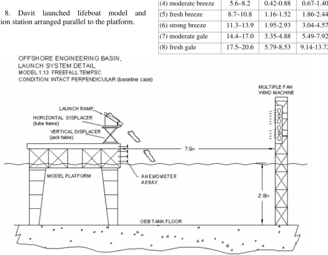
Figure 8. Davit launched lifeboat model and evacuation station arranged parallel to the platform.
Figures 9, 10 and 11 show the arrangements used for the free-fall experiments, the TEMPSC system oriented perpendicular to the platform, and the TEMPSC system oriented parallel to the platform. In the latter two cases, experiments were done with and without a flexible boom.
In the Figures 9 to 11, regular waves propagated from right to left. Each environmental condition was modeled using an average wind and a regular wave of a specific height and period that, when combined, constituted an
equivalent Beaufort condition. Conditions ranged from
calm to approximately Beaufort 8 (equivalent) and included several nominally discrete weather conditions in between. Tests with the TEMPSC systems were done in six conditions, as shown in Table 1. The same conditions were used for the free-fall system, except for the moderate breeze environment, which was not modeled. Significant wave heights from the Beaufort scale were used as the target regular wave heights in the experiments.
Table 1. Nominal environmental conditions.
(Beaufort) description Mean wind speed Average wave height Significant wave height [m⋅s-1 ] [m] [m] (0) calm water 0 0 0 (4) moderate breeze 5.6–8.2 0.42-0.88 0.67-1.40 (5) fresh breeze 8.7–10.8 1.16-1.52 1.86-2.44 (6) strong breeze 11.3–13.9 1.95-2.93 3.04-4.57 (7) moderate gale 14.4–17.0 3.35-4.88 5.49-7.92 (8) fresh gale 17.5–20.6 5.79-8.53 9.14-13.72
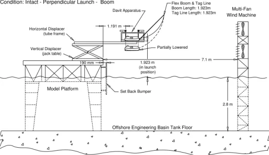
Flex Boom & Tag Line Boom Length: 1.923m Tag Line Length: 1.923m
Offshore Engineering Basin Tank Floor
Condition: Intact - Perpendicular Launch - Boom
190 mm Vertical Displacer (jack table) Model Platform Model: 1:13 TEMPSC Horizontal Displacer (tube frame)
Offshore Engineering Basin, Experimental Setup
1.191 m 1.923 m (in launch position) 7.1 m 2.8 m Set Back Bumper
Davit Apparatus
Wind Machine Multi-Fan
Partially Lowered
Figure 10. Test arrangement: TEMPSC lifeboat orientated perpendicular to the platform. The flexible boom is also shown.
(partially lowered position) 0.372 m
Wind Machine Multi-Fan
Flex Boom & Tag Line Boom Length: 1.923m Tag Line Length: 1.923m
2.8 m 7.1 m Davit Apparatus
1.405 m
1.923 m (in launch position)
Model Platform
Vertical Displacer (jack table)
Offshore Engineering Basin Tank Floor
Set Back Bumper 190 mm
Offshore Engineering Basin, Experimental Setup
Condition: Intact - Parallel Launch - Boom
Horizontal Displacer (tube frame) Model: 1:13 TEMPSC
Figure 11. Test arrangement: TEMPSC lifeboat orientated parallel to the platform. The flexible boom is also shown.
RESULTS Scope
Results are presented below for all three systems so that comparisons can be made concerning their performance. For all three systems, the main investigation concerned performance over a range of weather conditions, as indicated in Table 1. As measures of performance, the focus here is on setback and the directness of the paths taken by the lifeboats during the sail-away (or clearing) phase of the evacuation process.
Results are also presented here of important configuration variations, namely, perpendicular and parallel launch arrangements for the davit launched systems. Free-fall lifeboats would normally be arranged perpendicular to the platform, which the experiments also modeled, or at the stern of a ship. Most of the free-fall test launches were made into head seas, but some launches into oblique seas (up to 40° off the bow) were also made.
The experiments also investigated the effects of wave steepness on performance and results showing these effects are also presented. More results were acquired than can be presented here, but the interested reader can expect to see additional results in subsequent publications.
To begin, examples of the launch process are shown for each system to highlight some important attributes of each. Results of multiple launches are then presented by tracing out their paths from launch to clearing to the rescue zone. These plots show a footprint of the sail- away process for the various evacuation systems and configurations. Multiple launch results are then presented in terms of the extent to which the different lifeboats were setback after launch. The effects of the wave steepness and the splash-down position with respect to wave phase are then examined for the sail-away paths and the setback. Throughout, comparisons are made between the three systems and configurations.
Examples of launching: free-fall
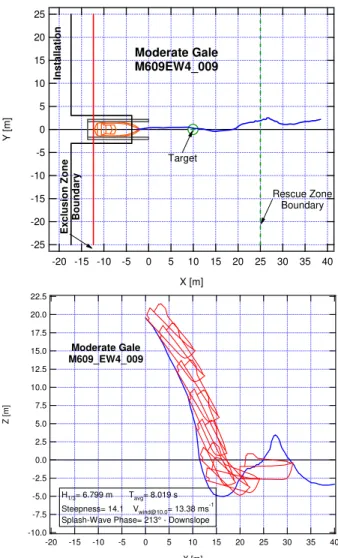
An example of a successful free-fall launch is shown in Figure 12 for moderate gale weather conditions with approximately 7m high (full scale) waves with a nominal steepness of 15. Two views are illustrated. The top one shows a plan view of the launch site, including an outline of the free-fall lifeboat on its ramp prior to launch. Some notional boundaries used in the measurement of performance are also indicated in this view, including the target drop point for the lifeboat and a nominal exclusion zone boundary around the installation. An x-y coordinate system is superimposed on the plan view. The corresponding profile view is shown in the bottom part of the figure, with a superimposed x-z coordinate system. In both views, the
path of a single point in the lifeboat’s reference frame is traced out. The point corresponds to the intersection of the flat stern and keel line, which is the origin of the boat’s coordinate system.
In this case, the x-z view shows that the lifeboat followed a smooth trajectory as it left the ramp and entered the water on the down-slope of a wave. The outline of the boat is superimposed at several points to illustrate its orientation during the launch process. The path dropped smoothly below the mean water level, resurfaced at the trough and then crested a wave just beyond the rescue zone.
The plan view shows that the free-fall boat hit the target launch point accurately and then moved away from the platform at a fairly straight heading during the entire launch and sail-away process, which was completed rapidly. There was only minor lateral displacement en route to the rescue zone, and little pitch and roll motion.
-25 -20 -15 -10 -5 0 5 10 15 20 25 Y [ m ] 40 35 30 25 20 15 10 5 0 -5 -10 -15 -20 X [m] Moderate Gale M609EW4_009 Rescue Zone Boundary E x cl us ion Zone Bounda ry In st all a ti o n Target 22.5 20.0 17.5 15.0 12.5 10.0 7.5 5.0 2.5 0.0 -2.5 -5.0 -7.5 -10.0 Z [m ] 40 35 30 25 20 15 10 5 0 -5 -10 -15 -20 X [m] Moderate Gale M609_EW4_009 H1/3= 6.799 m Tavg= 8.019 s Steepness= 14.1 [email protected]= 13.38 ms -1
Splash-Wave Phase= 213° - Downslope
Figure 12. Plan (top) and elevation (bottom) views of path taken by free-fall lifeboat in moderate gale conditions.
For simplicity, the path traced out by only a single point on the lifeboat is shown in the figure. The paths shown in the two views do not correspond exactly due to the means used to measure it. Two video cameras were used to record the position. The more reliable of the two was the overhead camera, which is the plan view in Figure 12 and in similar figures following.
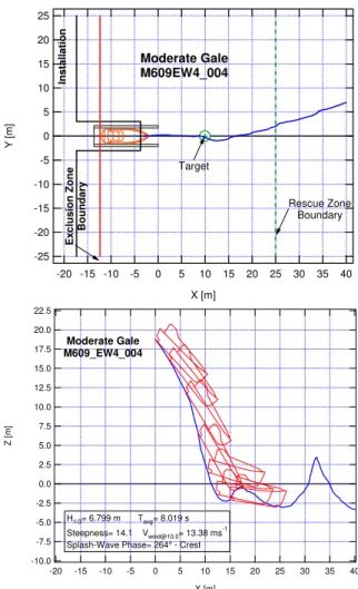
Figure 13 shows another example of a successful free-fall launch into moderate gale conditions with the same nominal wave steepness (15) as in the previous example in Figure 12. In this case, the lifeboat entered the water at a wave crest and briefly submerged before emerging on the down-slope. It then sailed into the trough and crested a second wave after having reached the rescue zone. The launch was smooth and quick, with very little pitch and roll motion, and a fairly steady heading. -25 -20 -15 -10 -5 0 5 10 15 20 25 Y [ m ] 40 35 30 25 20 15 10 5 0 -5 -10 -15 -20 X [m] Moderate Gale M609EW4_004 Rescue Zone Boundary E x cl us io n Zone Bo u n d a ry In stal lati on Target 22.5 20.0 17.5 15.0 12.5 10.0 7.5 5.0 2.5 0.0 -2.5 -5.0 -7.5 -10.0 Z [m ] 40 35 30 25 20 15 10 5 0 -5 -10 -15 -20 X [m] Moderate Gale M609_EW4_004 H1/3= 6.799 m Tavg= 8.019 s Steepness= 14.1 [email protected]= 13.38 ms -1
Splash-Wave Phase= 264° - Crest
Figure 13. Plan and elevation views of free-fall lifeboat’s path during launch in moderate gale conditions.
Another example of a free-fall launch into the same nominal conditions (moderate gale, wave steepness 15) is presented in Figure 14. This case is very different
from the successful launches illustrated in Figures 12 and 13, largely because the boat entered the water in a wave trough. It resurfaced on the up-slope of the following wave at which point the stern section was out of the water, but the boat maintained some forward way. The incoming wave stopped the boat’s forward progress. From the profile view, it is clear that the boat was setback significantly during this encounter. After the initial setback, it made some headway after the first crest passed, but was setback by about 4m during its second wave encounter and then crested another wave before making the rescue boundary. The plan view shows that the lifeboat moved to port after it surfaced and was then brought under control and headed away from the installation.
-25 -20 -15 -10 -5 0 5 10 15 20 25 Y [m] 40 35 30 25 20 15 10 5 0 -5 -10 -15 -20 X [m] Moderate Gale M609_AW4_005 Rescue Zone Boundary E x c lus ion Z one B ou nda ry In st alla tio n Target 20.0 17.5 15.0 12.5 10.0 7.5 5.0 2.5 0.0 -2.5 -5.0 -7.5 -10.0 Z [ m ] 40 35 30 25 20 15 10 5 0 -5 -10 -15 -20 X [m] Moderate Gale M609_AW4_005 H1/3= 6.799 m Tavg= 8.019 s Steepness= 14.1 [email protected]= 13.38 ms -1
Splash-Wave Phase= 77° - Trough
Figure 14. Plan and elevation views of free-fall lifeboat’s path during launch in moderate gale conditions.
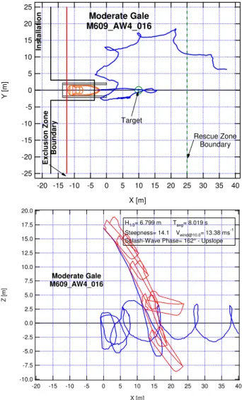
The final example of a free-fall launch is shown in Figure 15, again for the same weather conditions. This time, the lifeboat entered the water on the up-slope of an incoming wave and surfaced at the crest. The
consequences are dramatic. Upon surfacing, it rolled approximately 90° onto its port side, was setback significantly, and deviated more than 40° from its intended heading. It was setback further by the next wave, which resulted in a collision with the platform. It recovered its heading after the collision and made way to the rescue zone, although with difficulty at each subsequent wave encounter. Compared to the cases where the boat landed on a down-slope and a crest, the performance when landing on the up-slope was very poor. The plan view shows that the lifeboat moved quite erratically after its launch, ending up well to the port of the evacuation station.
-25 -20 -15 -10 -5 0 5 10 15 20 25 Y [ m ] 40 35 30 25 20 15 10 5 0 -5 -10 -15 -20 X [m] Moderate Gale M609_AW4_016 Rescue Zone Boundary Exc lusion Zo ne Bo un dar y In s tal lat io n Target 20.0 17.5 15.0 12.5 10.0 7.5 5.0 2.5 0.0 -2.5 -5.0 -7.5 -10.0 Z [ m ] 40 35 30 25 20 15 10 5 0 -5 -10 -15 -20 X [m] Moderate Gale M609_AW4_016 H1/3= 6.799 m Tavg= 8.019 s Steepness= 14.1 [email protected]= 13.38 ms -1
Splash-Wave Phase= 162° - Upslope
Figure 15. Plan and elevation views of free-fall lifeboat’s path during launch in moderate gale conditions.
These four examples demonstrate clearly the significance of the launch point on the wave in terms of the performance of the evacuation.
Mathematical models of free-fall launches have been developed by [14-26] and used to examine the launch
parameters of free-fall evacuation stations and accelerations in terms of (human) response criteria. The focus of much of these previous studies has been on ensuring that the launch arrangement (e.g. ramp angle, length, height) will result in successful launches and that occupants will avoid injury.
Using a two-dimensional numerical model of the free-fall launch process, [22-23] provided a useful classification of launch outcomes that might be expected for a given launch arrangement, all for calm water. Basically, the launches were categorized as successful or unsuccessful based on the motions of the vessel upon launch. These are described briefly here and then used to categorize the examples shown above.
Successful launches were described in [22] as one of two sorts: type Ia and type Ib. The best sort is type Ia, which was characterized by a smooth entry into the water followed by surfacing with forward headway in a straight direction, away from the launch ramp. Despite the fact that the categories in [22] were based on simulated launches in calm water, we have interpreted the examples presented in Figures 12 and 13 as being of the Ia sort. Type Ib launches were described in [22] as being similar to type Ia, but with the difference that the lifeboat has more heaving motion after it surfaces and moves away from the launch site. Still, this type is also in the successful category. None of the examples above were interpreted as type Ib, but such cases were certainly observed in the course of the experimental campaign.
In a type IIa launch, the lifeboat makes headway during the splash-down, but surfaces with negative velocity. That is, it moves backwards in the direction of the launch. In a type IIb launch, the lifeboat reverses direction during submergence and surfaces with negative velocity, that is, in the direction it entered the water. The examples shown in Figures 14 and 15 are, in our interpretation, best categorized as types IIa and IIb, respectively. Both sorts of type II launches are unsuccessful.
It bears repeating that these categories were based on calm water launches with a two-dimensional numerical model, but are still useful for categorizing in broad terms the types of launches observed during the model test campaign. Examples of all the launch classes in [22] were observed in the test program, with the added complications of waves and three-dimensional effects. Three-dimensional effects include substantial deviations in headway, and the motions (roll, yaw etc.) of the vessel during and after splash-down. The effects of wave height, steepness, and phase are described in more detail following, particularly in terms of setback.
Examples of launching: TEMPSC (perpendicular)
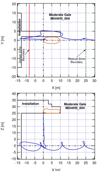
Figure 16 shows an example of a launch using a conventional TEMPSC (without the flexible boom) arranged perpendicular to the platform. The path taken by the lifeboat during this launch (again in moderate gale conditions) is shown as in the previous examples, where the irregular line in both views is the path of a reference point at the stern of the lifeboat as tracked by the optical tracking system. The origin of the axis system is the target drop point. The boat splashed down on the up-slope of an incoming wave and was setback more than 13m towards the platform, where it collided while on the wave crest before moving away again, cresting three waves en route to the rescue zone.
-20 -15 -10 -5 0 5 10 15 20 Y [m ] 30 25 20 15 10 5 0 -5 -10 -15 X [m] Installation Dange r Z one Bo undary Rescue Zone Boundary Moderate Gale M544H5_004 40 35 30 25 20 15 10 5 0 -5 -10 Z [m] 30 25 20 15 10 5 0 -5 -10 -15 X [m]
Installation Moderate Gale
M544H5_004
Figure 16. Plan and elevation views of TEMPSC’s (w/o boom) path during launch in moderate gale conditions (perpendicular orientation).
A similar example is presented in Figure 17, this time for a launch with a flexible boom. The elevation shows that the flexible boom was already effective during lowering: the path is not vertically downward,
but rather slants away from the platform and is about 2m farther out from the target drop point at splash-down. Immediately after launching on an up-slope, the lifeboat was pushed back toward the platform during its first wave encounter, but its setback was mitigated by the action of the boom. It then proceeded ahead and crested two more waves en route to the rescue zone. The tag line attached to the lifeboat’s bow and the tip of the flexible boom was under tension and both pulled the boat away from the platform and kept its bow pointed out, which helped the vessel maintain direction. This guiding force was active until the boat passed under the tip of the boom and the tag line released, which occurred in this case at about 25m (full scale) out from the target drop point.
-20 -15 -10 -5 0 5 10 15 20 Y [ m ] 30 25 20 15 10 5 0 -5 -10 -15 X [m] Instal lation D ang er Zo ne Bou nda ry Rescue Zone Boundary Moderate Gale M544A5_003 45 40 35 30 25 20 15 10 5 0 -5 -10 Z [m ] 30 25 20 15 10 5 0 -5 -10 -15 X [m] Installation Moderate Gale M544A5_003
Figure 17. Plan and elevation views of TEMPSC’s (with boom) path during launch in moderate gale conditions (perpendicular orientation).
This exemplifies the general finding that the flexible boom was effective in mitigating setback and reducing the likelihood of collisions with the platform.
Examples of launching: TEMPSC (parallel)
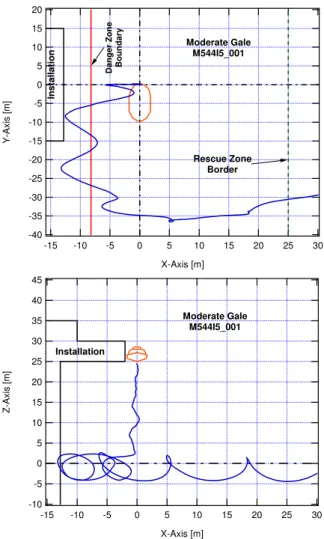
Figure 18 shows another example of a launch in moderate gale conditions, this time using a conventional
TEMPSC (without the flexible boom) arranged parallel
to the platform. The path taken by the lifeboat during this launch included initial setback upon launch into beam seas and further setback during the following two wave encounters with some headway made in between waves. After being progressively setback during the first few wave encounters, the lifeboat finally turned into the head seas and made its way to the rescue zone.
-40 -35 -30 -25 -20 -15 -10 -5 0 5 10 15 20 Y-Ax is [ m ] 30 25 20 15 10 5 0 -5 -10 -15 X-Axis [m] In stall a tion Da nge r Zo ne Bo und ar y Rescue Zone Border Moderate Gale M544I5_001 45 40 35 30 25 20 15 10 5 0 -5 -10 Z-A x is [ m ] 30 25 20 15 10 5 0 -5 -10 -15 X-Axis [m] Installation Moderate Gale M544I5_001
Figure 18. Plan and elevation views of TEMPSC’s (w/o boom) path during launch in moderate gale conditions (parallel orientation).
Figure 19 shows an example similar to Figure 18, but this time for a launch with a flexible boom. The example shows that the effect of the flexible boom is somewhat different for the parallel orientation compared to the perpendicular arrangement. From the plan view, it is apparent that the tag line between the boat and the boom turned the bow out away from the
platform already during lowering. This continued after splash-down, which made the transition to a heading 90° away from the platform faster than was the case without the boom. In both cases, the launch occurred on a similar point on the wave profile and the initial setback was comparable. The boom appeared to have a positive effect by orienting the bow of the lifeboat in the Figure 19 case into the head seas and thus avoiding the beam seas, thereby mitigating the progressive setback evident in Figure 18. -30 -25 -20 -15 -10 -5 0 5 10 15 20 Y-Ax is [m] 30 25 20 15 10 5 0 -5 -10 -15 X-Axis [m] In st a llat io n Danger Zone Bo undar y Rescue Zone Border Moderate Gale M544B5_001 45 40 35 30 25 20 15 10 5 0 -5 -10 Z-Axi s [m ] 30 25 20 15 10 5 0 -5 -10 -15 X-Axis [m]
Installation Moderate Gale M544B5_001
Figure 19. Plan and elevation views of TEMPSC’s (with boom) path during launch in moderate gale conditions (parallel orientation).
Comparison of sail-away paths: footprints
The examples shown in Figures 12 to 19 are just a few of the several hundred test launches done with the various evacuation systems. The samples shown so far were all for the same nominal weather condition (moderate gale and wave steepness 1:15), although the test conditions included a range of weather conditions (Table 1) and a systematic variation in wave steepness.
Rather than look at more individual examples, Figures 20 to 24 show sail-away paths (plan views) for numerous launches for the five evacuation station arrangements: free-fall, TEMPSC perpendicular to the platform both without and with a flexible boom, and
TEMPSC arranged parallel to the platform both without
and with a flexible boom. While it is not possible to discern individual launch paths in these figures, nor the effects of weather conditions, they give an overall impression of the performance of the systems and configurations.
Figure 20 shows results for the free-fall boat. The plot is for a range of weather conditions from calm to fresh gale, all in nominal wave steepness of 1:10. The results indicate that for some launches at least, the free-fall boat experienced significant setback (and progressive setback) and had difficulty gaining control and making way to the rescue zone.
-40 -30 -20 -10 0 10 20 30 40 Y [m] 40 35 30 25 20 15 10 5 0 -5 -10 -15 -20 X [m] Deploy. System: Freefall
Orientation: Perpendicular Installation: Intact Steepness: 10 Ramp Angle: 35° BF0 (W1) BF6 (W3) BF7 (W4) BF8 (W5)
Figure 20. Sail-away paths for multiple free-fall boat launches in a range of weather conditions (1:10 wave steepness).
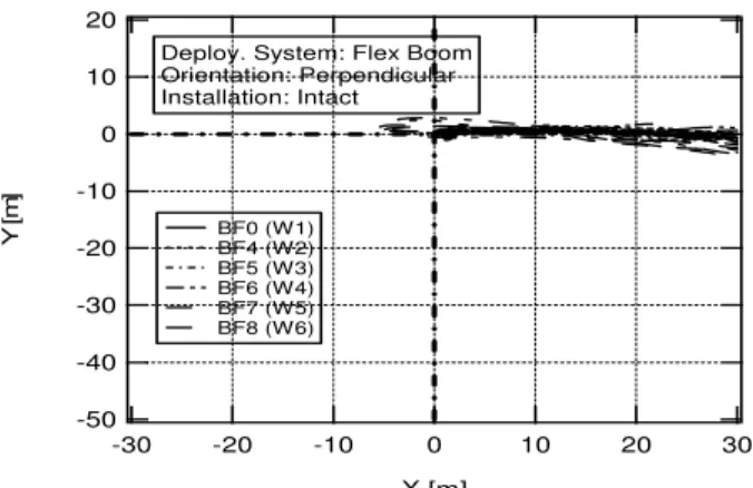
Figures 21 and 22 show results for the TEMPSC
arranged perpendicular to the platform and Figures 23 and 24 are for the TEMPSC in the parallel arrangement. No boom was used in the launches in Figures 21 and 23. The flexible boom was used in the tests presented in Figures 22 and 24. All four plots are for results over a range of weather conditions (from calm water up to fresh gale), all in nominal wave steepness of 1:15.
Several conclusions can be drawn from comparisons of the plots. First, the sail-away paths were much more
direct and in control for the TEMPSC in the perpendicular arrangement compared to both the parallel arrangement and free-fall boat. With respect to
the TEMPSC options, the effect of the flexible boom was
generally to reduce setback (and progressive setback) and increase control of the boat in terms of heading to the rescue zone.
-50 -40 -30 -20 -10 0 10 20 Y [ m ] -30 -20 -10 0 10 20 30 X [m]
Deploy. System: Davit Orientation: Perpendicular Installation: Intact BF0 (W1) BF4 (W2) BF5 (W3) BF6 (W4) BF7 (W5) BF8 (W6)
Figure 21. Sail-away paths for multiple TEMPSC (w/o boom) launches (perpendicular arrangement).
-50 -40 -30 -20 -10 0 10 20 Y [ m ] -30 -20 -10 0 10 20 30 X [m]
Deploy. System: Flex Boom Orientation: Perpendicular Installation: Intact BF0 (W1) BF4 (W2) BF5 (W3) BF6 (W4) BF7 (W5) BF8 (W6)
Figure 22. Sail-away paths for multiple TEMPSC (with boom) launches (perpendicular arrangement).
-50 -40 -30 -20 -10 0 10 20 Y [ m ] -30 -20 -10 0 10 20 30 X [m] BF0 (W1) BF4 (W2) BF5 (W3) BF6 (W4) BF7 (W5) BF8 (W6)
Deploy. System: Davit Orientation: Parallel Installation: Intact
Figure 23. Sail-away paths for multiple TEMPSC (w/o boom) launches (parallel arrangement).
-50 -40 -30 -20 -10 0 10 20 Y [ m ] -30 -20 -10 0 10 20 30 X [m]
Deploy. System: Flex Boom Orientation: Parallel Installation: Intact BF0 (W1) BF4 (W2) BF5 (W3) BF6 (W4) BF7 (W5) BF8 (W6)
Figure 24. Sail-away paths for multiple TEMPSC (with boom) launches (parallel arrangement).
The effect of weather conditions on the sail-away phase of the evacuations can be seen in Figures 25, 26, and 27 for the free-fall system, the TEMPSC arranged perpendicular to the platform, and the TEMPSC arranged parallel to the platform, respectively. The path length from the lifeboat’s splash-down to where the rescue zone was crossed is plotted against wave height.
For each case, there is considerable variability in the results for any given weather condition. Further, it is apparent too that the worst case in each weather category tends to increase with deteriorating weather conditions.
With reference to Figure 25 for the free-fall evacuation system, the baseline path length was established by the calm water launches to be about 14m to 18m, as indicated in the figure. Similar path lengths were observed for some launches in all other weather conditions too, including launches in Beaufort 8 (equivalent) conditions. However, the worst cases for the Beaufort 6, 7 and 8 weathers were about 85m, 100m and 107m respectively. 120 110 100 90 80 70 60 50 40 30 20 10 0 P a th le n g th [ m ] 10 9 8 7 6 5 4 3 2 1 0 Wave Height [m] Freefall
Freefall Lifeboat Deployment System Splashdown to Rescue Border
Perpendicular Deployments Be au fo rt 0 B eau fo rt 6 Be au fo rt 7 Beau fo rt 8
Figure 25. Sail-away path length (to rescue zone) versus wave height for free-fall evacuation tests.
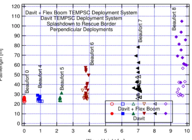
The same can be observed in Figure 26 where the path length is plotted against wave height for the perpendicular TEMPSC arrangement. In general, the path lengths are longer for the free-fall launches than
the TEMPSC when launched into head seas. Launches
using the davits alone are indicated by solid symbols; launches with the boom are indicated by open symbols. The effectiveness of the boom in reducing the path lengths at the upper end of each weather condition is obvious for the conditions above Beaufort 5. At Beaufort 8, the maximum path length experienced without the boom was about twice that with the boom.
120 110 100 90 80 70 60 50 40 30 20 10 0 Pathlength [m] 10 9 8 7 6 5 4 3 2 1 0 Wave Height [m] Davit + Flex Boom TEMPSC Deployment System
Davit TEMPSC Deployment System Splashdown to Rescue Border
Perpendicular Deployments B eauf or t 0 Beaufor t 4 Beaufor t 5 B eauf o rt 6 Beau fo rt 7 Be auf or t 8
Davit + Flex Boom Davit
Figure 26. Sail-away path length versus wave height for
TEMPSC (perpendicular arrangement).
Figure 27 displays generally similar results as Figure 26 in the sense that the worst cases for a given weather condition tend to worsen as wave height increases, and that the boom was effective in reducing the worst of the path lengths. In general, the path lengths observed in launches with the TEMPSC arranged parallel to the platform were worse that the perpendicular arrangement, although this is largely a function of the fact that one was launched into head seas and the other into beam seas.
120 110 100 90 80 70 60 50 40 30 20 10 0 Pa thleng th [m] 10 9 8 7 6 5 4 3 2 1 0 Wave Height [m] Davit + Flex Boom TEMPSC Deployment System
Davit TEMPSC Deployment System Splashdown to Rescue Border
Parallel Deployments B eaufor t 0 B e a u for t 4 B eaufort 5 B eauf or t 6 B eauf or t 7 B eaufort 8
Davit + Flex Boom Davit
Figure 27. Sail-away path length versus wave height for
Comparison of setback
Setback was found to be a key performance measure and is the focus of the results presented in Figures 28 to 34. Figure 28 gives results for free-fall launches over the full range of weather conditions, all at a nominal wave steepness of 15. The plot shows the launch target at the origin and the open symbols represent the location farthest from the target to which the lifeboat was setback after launch. In all the cases shown, the setback was primarily in the direction of the waves. The maximum setback increased as the weather conditions deteriorated. Progressive setback is not shown.
-15.0 -12.5 -10.0 -7.5 -5.0 -2.5 0.0 2.5 5.0 7.5 10.0 12.5 15.0 Y [m] -30 -25 -20 -15 -10 -5 0 5 X [m]
Freefall Deployment System Setback
BF0 BF6 BF7 BF8
Figure 28. Setback for free-fall launches in a range of weather conditions with wave steepness 1:15.
The maximum setback measured in each test launch is presented in Figure 29 for the free-fall launches in 1:15 wave steepness conditions, for a range of weather conditions, represented in the plot by measured wave height. There was no setback in calm conditions. For any other given weather condition, the results in the plot show there was a high degree of variability, which is similar to the results seen above for the path length measure. In Beaufort 7 conditions, for example, several launches had almost no setback, but the maximum setback measured in that series of tests at that nominal weather condition was 22m. This is a significant performance measure, particularly as it relates to the potential for collisions between the lifeboat and platform, and therefore on the design of the evacuation arrangement. The line in the plot indicates roughly that the upper measured value of setback increased approximately linearly with (∼2.8 ×) wave height.
Similar plots of setback versus wave height are shown in Figure 30 for the TEMPSC arranged perpendicular to the platform and in Figure 31 for the
TEMPSC arranged parallel to the platform. In both of
these plots, results are shown for the lifeboat with and without the flexible boom.
30.0 27.5 25.0 22.5 20.0 17.5 15.0 12.5 10.0 7.5 5.0 2.5 0.0 Se tb a c k [ m ] 10 9 8 7 6 5 4 3 2 1 0 Wave Height [m] B e uaf ort 0 Be ua fo rt 6 B e uaf ort 7 Be ua fo rt 8
Freefall Deplyment System
Perpendicular Deployment
Freefall Upper Bound
Figure 29. Setback versus weather conditions: free-fall.
22.0 20.0 18.0 16.0 14.0 12.0 10.0 8.0 6.0 4.0 2.0 0.0 S e tb a ck [m ] 10 9 8 7 6 5 4 3 2 1 0 Wave Height [m] B eauf or t 0 B eauf or t 4 Be auf ort 5 B eauf or t 6 Beauf or t 7 B eauf or t 8
Davit + Flex Boom Deplyment System Davit Deplyment System
Perpendicular Deployment Davit +Flex Boom
Davit
Upper Bound Davit+Flex Boom Upper Bound Davit
Figure 30. Setback versus weather conditions: TEMPSC
in perpendicular arrangement. 22 20 18 16 14 12 10 8 6 4 2 0 Se tb ac k [m ] 10 9 8 7 6 5 4 3 2 1 0 Wave Height [m]
Davit + Flex Boom Deplyment System Davit Deplyment System
Parallel Deployment Beau fo rt 0 Be auf or t 4 Beau fo rt 5 Be au fo rt 6 Bea u fo rt 7 Be auf or t 8 Davit+Flex Boom Davit Upper Bound
Figure 31. Setback versus weather conditions: TEMPSC
Figure 30 shows similar trends in performance in terms of setback as are evident in Figure 29, including that the upper limit increases approximately linearly with wave height. One line is shown for the TEMPSC
with the flexible boom (∼1.3 × wave height) and the other is for launches without the boom (∼2.1 × wave height). These results indicate that the effect of the boom when used with a TEMPSC arranged perpendicular to the platform is to reduce the maximum setback. Again, this is significant in terms of evacuation system design, for example in terms of ensuring suitable clearance between the platform and the launch target.
The boom had less effect on setback when used in conjunction with the parallel launch arrangement, as indicated in Figure 31. A single upper bound line is used for both (∼2.0 × wave height) in Figure 31. The boom launches were generally just marginally better in terms of setback, although, as seen above, the boom system did improve performance in terms of path length when used in this arrangement, reflecting its utility in limiting progressive setback and improving control.
A comparison of the upper bound for each system can be made using these three figures. Interestingly, the maximum setback for the conventional TEMPSC is much the same regardless of orientation to the platform. Further, the influence of the boom on maximum setback is significant for the perpendicular arrangement but not for the parallel arrangement. Compared to the TEMPSC
configurations, the performance of the free-fall boat was poorer. It bears repeating at this point that all the test launches were made into collinear wind and waves that were perpendicular to the launch platform, such that launches of the free-fall boat and TEMPSC in the perpendicular arrangements were into heads seas, and launches of the TEMPSC in the parallel arrangement were into beam seas.
Effects of wave phase
Figures 32 to 34 show setback plotted against the position on the wave of the lifeboat’s splash-down point. With reference to Figure 32, the trend is clear: setback is relatively small for launches made near the crest and down-slope of the wave compared to the relatively large setback measured in cases where the launch was in the wave trough or up-slope. Results of many tests are shown in the figure, including tests done in different weather conditions.
Similar results are shown in Figures 33 and 34 for
the TEMPSC evacuation station arranged perpendicular
and parallel, respectively, to the platform. These exhibited similar trends as the free-fall lifeboat. One difference between the TEMPSC and the free-fall is that the relatively slower lowering speed of the conventional
TEMPSC resulted in shadowing of the down-slope,
making launching there unlikely.
25.0 22.5 20.0 17.5 15.0 12.5 10.0 7.5 5.0 2.5 0.0 Setb ac k [m ] 360 315 270 225 180 135 90 45 0
Wave Phase Angle [Degrees]
Down-Slope Trough Up-Slope Down-Slope
Crest BF0 BF6 BF7 BF8
Freefall Deplyment System Perpendicular Deployments
Figure 32. Setback versus wave phase: free-fall.
25.0 22.5 20.0 17.5 15.0 12.5 10.0 7.5 5.0 2.5 0.0 Se tb ac k [m] 360 315 270 225 180 135 90 45 0
Wave Phase Angle (Degrees) Davit Deployment System Perpendicular Deployment Down-Slope Down-Slope Trough Up-Slope Crest BF4 BF5 BF6 BF7 BF8
Figure 33. Setback versus wave phase: perpendicular
TEMPSC. 25.0 22.5 20.0 17.5 15.0 12.5 10.0 7.5 5.0 2.5 0.0 Set bac k [m ] 360 315 270 225 180 135 90 45 0
Wave Phase Angle [Degrees] Davit Deployment System
Parallel Deployment Down-Slope Down-Slope Trough Up-Slope Crest BF4 BF5 BF6 BF7 BF8
Figure 34. Setback versus wave phase: parallel
These results show the importance of launch conditions in relation to wave phase on the overall performance of the launch and a corresponding opportunity to improve performance by coordinating the launch with the wave environment [27]. A comparison of the figures indicates that the worst of the free-fall cases were marginally worse than the other two arrangements.
Effects of wave steepness
Wave steepness was varied in the experiments so that its effects might be discerned. A plot of path length versus wave steepness is presented in Figure 35 for the free-fall tests. Each point represents the total length of the path taken by the vessel as it moved from splash-down to the rescue zone. For each of the nominal wave steepness values (10, 15 and 20) the results are highly scattered, reflecting again the effect of launch conditions in terms of wave phase. As wave steepness increased, the tendency was for the path length to increase as well. This is important as path length in this context is a proxy measure of the control and maneuverability of the lifeboat.
Figure 36 shows the same sort of results for the
TEMPSC in a perpendicular arrangement, without the
flexible boom. The trend that performance worsened with increasing wave steepness is repeated here. Note that a comparison of the results of the free-fall and
TEMPSC in the perpendicular arrangement shows that
the TEMPSC performance is better, even without the
flexible boom. As noted above (see Figure 26), the boom improves the performance in terms of the path length measure considerably. This result reflects the relatively erratic behavior experienced by the free-fall lifeboat when launched into unfavorable parts of the wave.
Launches of the TEMPSC arranged parallel to the platform (and without the flexible boom) are shown in Figure 37. A direct comparison of these results with the other two plots (Figures 35 and 36) is not reasonable as the boat in these cases (Figure 37) had to turn through 90° after launch in order to head to the rescue zone. Still, the role of steepness is evident again: steeper waves degrade performance.
160 140 120 100 80 60 40 20 0 P a th le n g th [ m ] 25.0 20.0 15.0 10.0 5.0 Wave Steepness
Freefall Deployment System Splashdown to Rescue Borber
Steepness 20 Steepness 15 Steepness 10
Figure 35. Steepness effects: free-fall.
140 120 100 80 60 40 20 0 P a th le ngt h [ m ] 25 20 15 10 5 Wave Steepness
Davit Deployment System Splashdown to Rescue Border
Perpendicular Deployment
Steepness 10 Steepness 15 Steepness 20
Figure 36. Steepness effects: perpendicular TEMPSC.
140 120 100 80 60 40 20 0 P a th length [m ] 25 20 15 10 5 Wave Steepness
Davit Deployment System Splashdown to Rescue Border
Parallel Deployment
Steepness 15 Steepness 20
SUMMARY
Three types of evacuation system were evaluated in an extensive experimental campaign using model tests in a large test facility. The aim of the work was to contribute to the knowledge concerning evacuation system performance, which can be used in the decision-making processes of operators, regulators and designers. The scope of the work included the technical performance of the evacuation systems, but excluded most human factors (e.g. mistakes and psychological considerations) and mechanical reliability (e.g. design faults and mechanical failures).
The main performance measures considered in the paper were setback at launch and the length of the path the boat took to clear to the rescue zone after launch. The former is an indicator of the evacuation system’s control at launch as well as the lifeboat’s likelihood of collision with the platform or ship. The latter is a proxy for the control and maneuverability of the lifeboat after launch. All of the test launches presented in the paper were made from a fixed platform that was largely transparent to waves.
Several examples of launches with the different systems were presented, including a series of examples of the free-fall system launched into head seas for the same nominal weather condition, but with different launching conditions in terms of where the lifeboat landed with respect to the wave phase. These examples typified and highlighted the wide variation in performance observed in the free-fall launches, a result that was attributed largely to the wave phase effect.
Examples were also presented of the conventional
TEMPSC evacuation system arranged perpendicular to
the platform (typical of an offshore petroleum installation) and the same system with the addition of a flexible boom and tagline in the arrangement. The examples illustrated a general observation from similar tests: that the flexible boom was effective in mitigating setback and reducing the likelihood of collisions with the platform, which is an important consideration when launching into head seas as in the tests.
Examples of test launches with the TEMPSC
arranged parallel to the installation, again with and without the boom, were also shown. It is important to recognize that launches in such conditions were into beam seas, rather than head seas as was the case for the free-fall launches and the perpendicular arrangement. The examples illustrated that the boom had the effect of turning the bow of the lifeboat away from the platform and into the head seas (where it had to go under the circumstances), thereby avoiding the persistent beam seas and mitigating the progressive setback that was more evident in the tests without the boom.
One of the key performance measures used to evaluate the evacuation systems was setback. For all of the systems, setback was a dominant feature and found
to be dependent on the wave phase at splash-down. For any given weather, launches resulted in a wide range of setback, from a minimum baseline value corresponding to the calm water case, up to some maximum. The maximum setback for the range of weather conditions was found for all systems to be approximately linear with wave height. A comparison of the different systems revealed that the maximum setback (as a function of wave height) was larger for the free-fall lifeboat than any of the TEMPSC configurations. The maximum setback for a given weather condition was similar for both of the TEMPSC arrangements (parallel and perpendicular) without the boom. Further, setback was significantly reduced by the boom in launches of the conventional TEMPSC in the perpendicular arrangement, but was not particularly influenced in the parallel arrangement. However, the boom did reduce the progressive setback in the parallel launches, indicating its utility in terms of improving control, at least in the launch scenarios in which the tests were done.
Test results were also presented in terms of the paths taken by the lifeboats after launch, as they moved to the rescue zone. These results took the form of ‘footprints’ consisting of the trajectory of the lifeboat over multiple tests, as well as plots of integrated path lengths. For all the systems, path length varied widely for any given weather condition, much like the setback measure discussed above. That is, it varied from some baseline value comparable to the measurement in calm conditions, up to a maximum that was sometimes many times longer than the baseline value. Also the longest path length for the given weather conditions tended to increase with deteriorating weather.
The free-fall test results showed that the free-fall lifeboat experienced significant setback and progressive setback in some launches (type II), reflecting the difficulty in gaining control of the boat and making way to the rescue zone. Interestingly, while some of the launches (type I) of the free-fall system in waves were excellent – even in heavy weather, the performance in others indicated more difficulty in terms of control and maneuverability than was experienced with the conventional TEMPSC lifeboats. Again, this is due to the sensitivity of performance on the entry point on the wave, to which the free-fall lifeboat seemed to be more sensitive than the conventional boats. This was also reflected in the plots of path length, which were longer for the free-fall boat than for the conventional TEMPSC
when launched in the perpendicular arrangement (both of which were into heads seas).
Sail-away paths for the conventional TEMPSC in the perpendicular arrangement were much more direct and in control compared to the free-fall system (launched into head seas) and the TEMPSC in the parallel arrangement (launched into beam seas). As noted elsewhere, the boom was effective in the perpendicular
arrangement at reducing setback, progressive setback and path lengths.
For launches using the parallel arrangement, the boom was helpful in reducing path length due to its utility in reducing progressive setback, which was otherwise a major feature of the parallel launches (without the boom) because they were into beam seas.
Wave steepness was also found to have an effect on performance. In particular, path length, the proxy for control and maneuverability during sail-away, was found to increase with increasing steepness for all the evacuation systems.
DISCUSSION
In general, the results presented provide some performance benchmarks for the different evacuation system configurations. The scope of the work should be borne in mind when application of the results to a given design scenario is contemplated. Our experiments are concerned with only the evacuation stage of an emergency response that must include both escape before evacuation and rescue after it. The experiments modeled the launching and clearing process during evacuation, and were assessed using performance measures such as setback.
The performance of the evacuation systems in the tests did not include mechanical issues, such as the reliability of the equipment, or launch failures due to design and operational faults. Nor were issues such as availability addressed, which are relevant to the overall emergency planning exercise as lifeboats may be damaged by the emergency initiating event, or may be undergoing maintenance when needed, for example. Similarly, human factors were not included in this work, except in terms of the relationship between vessel motions, injury criteria and motion sickness. The importance of various design and operational issues is reinforced in any number of accident reports and other studies that complement the present one [e.g. 28].
It is also worth highlighting that the experiments reported here all involved launches into oncoming weather, rather than launches on the lee side (or into oblique or following seas), and so represent one of many weather orientation conditions, albeit a relatively difficult one. Also the platform from which the launches were made was fixed and largely transparent to the waves, so the otherwise complicating motions of the platform were avoided, as were the effects of wave reflection and radiation. This should be borne in mind when considering the present results in terms of ship launches, where the conventional arrangement of
TEMPSC is parallel to the ship’s side and of free-fall is
at the stern. The latter in particular would be worth investigating further, specifically in following seas.
Indeed, launching a conventional lifeboat (in the conventional parallel arrangement) from a ship that is
oriented into the weather might be preferred to the other arrangements used in the experiments as in such a case, the boat would be launched into head seas, rather than beam seas. In fact, we have investigated this situation for an FPSO [7] and discussed the implications for passenger ships elsewhere [29]. Interestingly, in the test launches from the FPSO, there were no collisions observed between the lifeboat and vessel in the over 150 launches that covered a wide range of weather conditions. This was despite the relatively small clearance between the lifeboat and the vessel during the launch process. An investigation of lifeboat arrangement and deployment for this same sort of scenario, but based on a numerical approach that included waves and ship motions, as well as lifeboat motions during lowering, has been presented in [30].
Space limitations prevent us from including additional results that we have measured from the experimental campaign. Of particular interest are results of launches of all the systems from a damaged platform (with a combined list and trim), launches of the free-fall lifeboat into oblique seas, and measurements of lifeboat accelerations and motions that are relevant for human performance evaluation, including in terms of injury criteria and motion sickness. We hope to publish these additional results in due course.
CONCLUSIONS
The experimental campaign yielded extensive, objective benchmark measures of the performance of several evacuation systems and system configurations. None of the various alternatives can be described categorically as better than the others. Indeed, it is apparent that the type of evacuation system that best suits a particular set of circumstances is likely to be different for different circumstances. With this in mind, the experimental results presented here should be useful to designers, operators and regulators in making decisions concerning evacuation systems that are fit for their specific purpose.
ACKNOWLEDGMENTS
The authors acknowledge with gratitude the financial support provided by the following organizations: Transport Canada, Natural Resources Canada, Canadian Association of Petroleum Producers, National Research Council, Petroleum Research Atlantic Canada, Natural Sciences and Engineering Research Council, National Search and Rescue Secretariat, and the Terra Nova Project partners led by Petro-Canada. We also acknowledge the role of peers who have offered constructive criticism of this work, colleagues at the Canada-Newfoundland & Labrador Offshore Petroleum Board who have provided advice over a period of years, and the technical staff who have executed a lot of model tests.