Publisher’s version / Version de l'éditeur:
Vous avez des questions? Nous pouvons vous aider. Pour communiquer directement avec un auteur, consultez la
première page de la revue dans laquelle son article a été publié afin de trouver ses coordonnées. Si vous n’arrivez pas à les repérer, communiquez avec nous à [email protected].
Questions? Contact the NRC Publications Archive team at
[email protected]. If you wish to email the authors directly, please see the first page of the publication for their contact information.
https://publications-cnrc.canada.ca/fra/droits
L’accès à ce site Web et l’utilisation de son contenu sont assujettis aux conditions présentées dans le site LISEZ CES CONDITIONS ATTENTIVEMENT AVANT D’UTILISER CE SITE WEB.
63rd Canadian Geotechnical Conference & 1st Joint CGS/CNC-IPA Permafrost
Specially Conference (GeoCalgary) [Proceedings], pp. 1426-1434, 2010-09-12
READ THESE TERMS AND CONDITIONS CAREFULLY BEFORE USING THIS WEBSITE. https://nrc-publications.canada.ca/eng/copyright
NRC Publications Archive Record / Notice des Archives des publications du CNRC :
https://nrc-publications.canada.ca/eng/view/object/?id=959e921d-2cc4-4e91-a49b-3ad27461a40c
https://publications-cnrc.canada.ca/fra/voir/objet/?id=959e921d-2cc4-4e91-a49b-3ad27461a40c
NRC Publications Archive
Archives des publications du CNRC
This publication could be one of several versions: author’s original, accepted manuscript or the publisher’s version. / La version de cette publication peut être l’une des suivantes : la version prépublication de l’auteur, la version acceptée du manuscrit ou la version de l’éditeur.
Access and use of this website and the material on it are subject to the Terms and Conditions set forth at
Behaviour of expansive soils at a water distribution pipe site
Hu, Y.; Chowdhury, R.; Azam, S.
http://www.nrc-cnrc.gc.ca/irc
Be ha viour of e x pa nsive soils a t a w a t e r dist ribut ion pipe sit e
N R C C - 5 3 5 5 3
H u , Y . ; C h o w d h u r y , R . ; A z a m , S .
S e p t e m b e r 2 0 1 0
A version of this document is published in / Une version de ce document se trouve dans:
63rd Canadian Geotechnical Conference & 1st Joint CGS/CNC-IPA Permafrost
Specially Conference (GeoCalgary), Calgary, AB., Canada, September 12-16,
2010
The material in this document is covered by the provisions of the Copyright Act, by Canadian laws, policies, regulations and international agreements. Such provisions serve to identify the information source and, in specific instances, to prohibit reproduction of materials without written permission. For more information visit http://laws.justice.gc.ca/en/showtdm/cs/C-42
Les renseignements dans ce document sont protégés par la Loi sur le droit d'auteur, par les lois, les politiques et les règlements du Canada et des accords internationaux. Ces dispositions permettent d'identifier la source de l'information et, dans certains cas, d'interdire la copie de documents sans permission écrite. Pour obtenir de plus amples renseignements : http://lois.justice.gc.ca/fr/showtdm/cs/C-42
Behaviour of Expansive Soils at a Water
Distribution Pipe Site
Yafei Hu, Rudaba Chowdhury
National Research Council Centre for Sustainable Infrastructure Research, Regina, SK, Canada
Shahid Azam
Environmental Systems Engineering, University of Regina, Regina, SK, Canada
ABSTRACT
Water distribution pipes constructed in expansive clay soils are often subjected to severe distress subsequent to construction. Seasonal variations in climatic conditions cause alternate saturation-desaturation in soils that can result in periodic swelling and shrinkage of the expansive soils. The volume changes may cause severe differential movement that will eventually lead to pipe failures. Field instrumentation was installed to monitor the soil conditions around a section of water distribution pipe in an area with expansive soil and where pipe failures were known to be frequent. The instrumentation included sensors to measure in situ soil water content and soil suction, soil movement, soil stress and temperature. This paper presents the data from the first year of monitoring and discusses implications of the preliminary findings.
RÉSUMÉ
Arroser les tuyaux de distribution construits dans les sols d’argile expansifs sont souvent exposés à la détresse sévère subséquente à la construction. Les variations saisonnières dans les conditions climatiques causent alternent saturation-desaturation dans les sols qui peuvent avoir pour résultat l'accroissement et le recul périodique des sols expansif. Les changements de volume peuvent causer le mouvement potentiellement différentiel sévère qui menera finalement à la rupture des pipe-lines. Pour plus apprendre du comportement de sols expansifs autour des tuyaux d'eau, l'instrumentation de champ a été installée pour contrôler les conditions de sol autour d'une section de tuyau de distribution d'eau dans un secteur de sol expansif où les échecs de tuyau ont été sus pour être fréquents. L'instrumentation a inclus des détecteurs pour mesurer dans le contenu d'eau de sol de situ et l'aspiration de sol, le mouvement de sol, la tension de sol et la température. Ce papier présente les données du premier an d'interception et discute des implications des conclusions préliminaires.
1 INTRODUCTION
Lightly loaded structures like water pipes constructed in expansive soils are often subjected to severe distress subsequent to construction. The soil water content in expansive soils may fluctuate significantly due to seasonal imbalance between precipitation and evaporation/transpiration. This high variation in water content can result in considerable swelling or shrinking. Changes in soil volume can induce differential soil movement that can generate stresses in structures built on or buried in expansive soils. In some cases, the stresses are believed to be of such magnitude that they can cause failures of the structures.
Many municipalities in North America have water distribution and sewer systems located in expansive soils. Each year in the United States alone, expansive soils cause over $2 billion in damage to roads, buildings and other structures (Keller, 1996, Montgomery, 1997). Some estimates are as high as $6 billion/year (Pipkin and Trent, 1994). Financial losses from expansive soils are approximately equal to those from all other geologic hazards combined (Montgomery, 1997). Therefore, it is critical to understand the behaviour of these soils and
their interaction with the structures built on/in expansive soils.
To understand the “working” environment and the corresponding responses of structures in expansive soils, field instrumentation was installed around a section of water main in an older area of Regina where frequent pipe breakage has been observed in recent years (Azam
et al., 2009a). A set of sensors was installed in a manner
that minimized soil disturbance. The instrumentation included sensors to measure in situ soil water content, soil suction, soil movement, soil pressure, and temperature. Measurements were made in the soils surrounding the section of water main. This paper presents the results of the first year of monitoring of the test section.
2 FIELD LOCATION AND SOIL CONDITIONS 2.1 Site location
The test site was located at Cross Place in the Hillsdale area of south Regina. This location was selected because it is in an area with a high number of asbestos cement (AC) pipe breaks. It was also located adjacent to
a previous field installation where a section of water main had been installed and instrumented (Hu et al., 2008). The new instrumentation at the site was intended to provide insight into the working environments of the water main pipes in undisturbed soil. The monitoring of the two field installations will provide insight into the different working environments of the newly installed water main pipes and those that have been in service for decades.
2.2 Soil conditions
One borehole (BH101) was drilled to a depth of about 9 m. The borehole was located on the street, about 0.8 m south of the centreline of the pipe. The stratigraphy (from the surface down) of the site is as follows: (i) gravel-sand-clay backfill to 1 m depth; (ii) clay backfill from 1 m to 3.5 m; (iii) sand-clay backfill from 3.5 to 4.5 m; (iv) clay from 4.5 to 7 m; and (v) glacial till from 7 to 9 m (Azam et al. 2009b). The top three layers are associated with the road construction and pipe installation whereas the bottom two layers pertain to geological history of the Regina area. Figure 1 shows the index properties and dry density of the soil sampled in the borehole.
3 FIELD MONITORING SYSTEM
Figure 2 shows the layout of the field instrumentation at Cross Place. The sensors were installed in the ground in May 2009. For the current study, installation was completed with minimal soil disturbance adjacent to a previously instrumented site, in which a section of AC water pipe, instrumented with strain gauges was installed
in a trench and backfilled, together with other sensors placed in the surrounding soil (Hu et al., 2008). The various sensors were installed at different depths (given in brackets in Figure 2) around the pipe that was at an average depth of 2.1 m. The water pipe was originally installed along the side of the street adjacent to a park area. Therefore, most of the moisture movement can be considered to be from the park area, namely: infiltration due to precipitation and park watering and evapo-transpiration from the grass and trees.
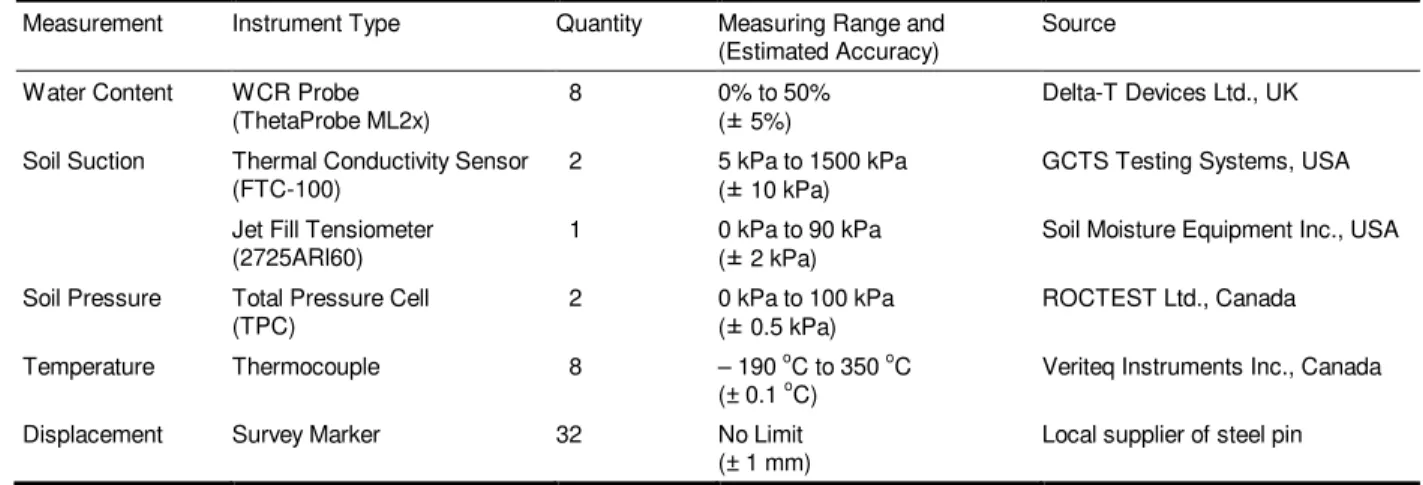
Table 1 gives the characteristics of the sensors selected for field installation. Five types of measurements are being recorded: (i) volumetric water content (by means of water content reflectometry (WCR) probes); (ii) soil suction (by means of thermal conductivity sensors and a jet fill tensiometer); (iii) soil pressure (by means of total pressure cells); (iv) temperature (by means of thermocouples); and (v) displacement (by means of survey markers). The sensors were selected based on low disturbance during installation, low maintenance, high data reliability, high precision, and low initial and operational costs. The first four types of measurements (except for the tensiometer) were recorded by an automated data acquisition system (DAQ). Manual readings of the jet fill tensiometer and survey markers were taken at regular intervals of time. Data are stored on site in the DAQ and transferred regularly to a portable computer for analysis.
More details on the instrumentation and layout can be found in Azam et al. (2009). The ongoing monitoring program should provide several years of continuous data on the soil conditions.
Figure 1. Soil index properties and dry density at the test site (after Azam et al., 2009b)
Figure 2: Layout of field instrumentation at Cross Place, Regina
Table 1: Characteristics of the selected sensors Measurement Instrument Type Quantity Measuring Range and
(Estimated Accuracy) Source Water Content WCR Probe
(ThetaProbe ML2x) 8 0% to 50% ( 5%) Delta-T Devices Ltd., UK Soil Suction Thermal Conductivity Sensor
(FTC-100) 2 5 kPa to 1500 kPa ( 10 kPa) GCTS Testing Systems, USA Jet Fill Tensiometer
(2725ARl60) 1 0 kPa to 90 kPa ( 2 kPa) Soil Moisture Equipment Inc., USA Soil Pressure Total Pressure Cell
(TPC) 2 0 kPa to 100 kPa ( 0.5 kPa)
ROCTEST Ltd., Canada Temperature Thermocouple 8 – 190 oC to 350 oC
(± 0.1 oC) Veriteq Instruments Inc., Canada
Displacement Survey Marker 32 No Limit
4 RESULTS AND DISCUSSION
The following results are based on the data collected in the one-year period following installation, from May 5, 2009 to April 21, 2010.
4.1 Temperature
Figure 3 shows the hourly temperatures at different depths at the east side of the installation. The average daily air temperature is also plotted for reference. The sensors at the west side of the installation experienced a similar temperature pattern (not shown). As expected, the soil temperature at every depth is affected by the seasonal temperature variation and the temperature variability decreases with depth below the ground surface. The deepest 0°C isotherm occurred about 1.8 m below the pavement surface around mid-March of the monitoring period.
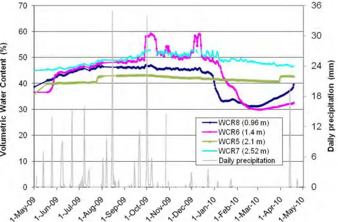
4.2 Soil water contents
The volumetric water contents for the four probes at the west side of the installation are shown in Figure 4. It also shows the daily precipitation data for the one-year period collected by Environment Canada at Regina International Airport. The water content values for all sensors tended to increase from May to mid October. This may indicate water infiltration through the ground surface due to relatively high precipitation from May to October. From October onward, all sensors experienced a slight, steady drop due to relatively low precipitation and high
evaporation. Some probes (e.g., WCR 6) near the ground surface registered significant increases in water content in early October and early December, probably due to leaks from cracks between the curb of the street and the pavement. Soils at both WCR6 and WCR8 experienced significant drops in measured water contents beginning late December and early January due to frost advance which caused freezing of the water in the soils (Rajani and Zhan, 1996). At depth of below 2.1 m, the soil did not freeze (TC4 in Figure 3) and measured water contents did not decrease dramatically (WCR 5 and WCR7 in Figure 4).
4.3 Soil suction
Figures 5 and 6 show the temperature rise, ∆T, measured by the FTC sensors at 2.0 m depth, and soil suction by the tensiometer at 2.5 m depth, respectively.
∆T values were not converted to soil suction values because the measured suction values were beyond the calibrated ranges of the sensors. A smaller temperature rise in Figure 5 indicates a lower soil suction. Also included in the figures are the cumulative rainfall deficit data for the one-year period starting from May 1, 2009. All the sensors indicate a general trend of decrease in soil suction, which is consistent with an increasing high cumulative rainfall deficit from May 1 to early October. A decrease in soil suction indicates an increase in soil water content at the measured locations. The increase in water content is also consistent with that recorded by the water content probes as shown in Figure 4.
Figure 3. Temperature at different depths at the east side of the installation
Figure 4. Volumetric water content at different depths
Figure 6. Soil suction measured by the tensiometer
4.4 Soil pressures
Figure 7 shows the horizontal earth pressures recorded by the two pressure cells. The soil pressure decreased from installation until early October and, then, fluctuated between about 20 and 40 kPa. The early drop in soil pressure may result from the stabilization process of the soils around the sensors immediately after their installation. The soil pressure recorded by EPC2 indicated two sudden jumps: one on August 15 and one on October 1. There were two major rainfall events on August 15 and October 1 of 35 and 34.2 mm respectively, or about 12% of annual precipitation. The sudden jumps in soil pressure by EPC2 recorded on August 15 and October 1 may have been due to the rainfall events. Water may have infiltrated into the soil around the pressure cell by means of the borehole housing the pressure cell.
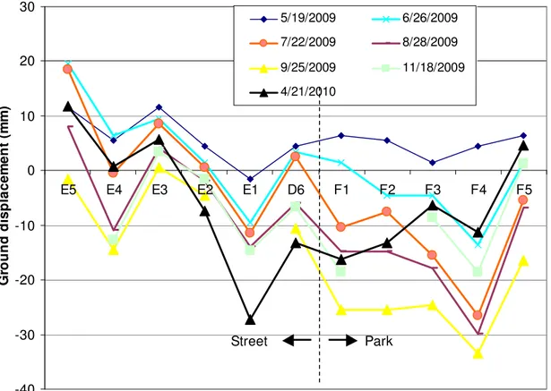
4.5 Soil displacements
The vertical ground displacements measured at the survey markers are shown in two figures: Figure 8 records the ground displacements along the water pipe
centerline; Figure 9 records the ground displacement perpendicular to the centerline of the water pipe. All the ground displacements are referred to the initial elevation readings on May 5, 2009, just after completion of the field installation. A positive value of displacement indicates heave, while a negative value indicates settlement since that date. There were no data measured from early December 2009 to early April 2010 due to snow/ice cover.
These figures indicate that the ground surface at the site experienced an initial upward movement until the end of May and then moved downward. It indicates that the ground surface was swelling in May due to infiltration of rainfall (Figure 4). By early summer, precipitation was not substantial enough to compensate for the loss in water content due to evaporation and transpiration, the soils then shrank, and the ground surface settled. It can also be observed from Figures 8 and 9 that the pavement tended to heave more than the ground surface in the park, but also to settle less than the ground surface in the park.
Figure 7. Horizontal earth pressure -30 -20 -10 0 10 20 D6 D5 D4 D3 D2 D1 B2 B3 B4 G ro u n d d is p la c e m e n t (m m ) 5/19/2009 6/26/2009 7/22/2009 8/28/2009 9/25/2009 11/18/2009 4/21/2010 East
-40
-30
-20
-10
0
10
20
30
E5
E4
E3
E2
E1
D6
F1
F2
F3
F4
F5
G
ro
u
n
d
d
is
p
la
c
e
m
e
n
t
(m
m
)
5/19/2009 6/26/2009 7/22/2009 8/28/2009 9/25/2009 11/18/2009 4/21/2010Park
Street
Figure 9. Ground displacements perpendicular to the water main centerline
5 SUMMARY AND CONCLUSIONS
A field installation was conducted to study the “working” environment of buried water mains in an area of Regina having a large inventory of asbestos cement water mains. This paper is a progress report of an ongoing data monitoring program.
The sensors installed include thermal conductivity sensors and a tensiometer for measuring soil suction; pressure cells in the water main backfill soil for measuring horizontal soil pressure; thermocouples for measuring soil temperature; water content reflectometry probes for measuring water content and survey markers for measuring ground surface movement. The tensiometric sensors, pressure cells, thermocouples and water content reflectometry probes are connected to an on-site datalogger and data are recorded continually and downloaded periodically. The intended monitoring period is two years, starting from May 2009.
The data recorded in the first year of the monitoring program indicate that most sensors are working well. Soil water contents recorded by the soil moisture probes responded reasonably well to changes in precipitation and temperature. Greater fluctuation between sensor readings was observed in sensors located near the
ground surface (thermocouples, soil moisture probes) due to the effects of seasonal climatic changes. Seasonal variation was evident in the recorded soil water contents, soil movement, and soil pressure.
The data recorded to date agree qualitatively with typical behaviour of clay soils. It also suggests that the water content of the soils at the pipe level increased continuously until mid October 2009, which coincided with a decrease in soil suction. The soil displacements at the ground surface were not evenly distributed, which are typical of the soil movement characteristics observed in the area.
With further data provided by ongoing field monitoring and analysis, it is expected that further insight into the soil working environments surrounding the water mains will be gained. The knowledge thus obtained will be used to compare with and verify the numerical analysis for this type of problem and evaluate the risks faced by water mains during their service.
ACKNOWLEDGEMENTS
The authors wish to acknowledge the financial support provided by the Communities of Tomorrow Inc. We
extend our appreciation to John Ullrich, Bob Youlyashshiev, Brian Wirth and his field team of the Engineering and Works Department at the City of Regina, and Brad Lafontaine of NRC-CSIR, for their invaluable assistance during the design and installation program.
REFERENCES
Azam, S., Hu, Y., and Chowdhury, R. 2009a. Sensor installation for field monitoring in expansive soils. 62nd Canadian Geotechnical Conference & 10th Joint CGS/IAH-CNC Groundwater Conference (Geohalifax 2009), Halifax, NS, September 20-24.
Azam, S., Ito, M., and Shah, I. 2009b. Behaviour of
asbestos cement water mains in expansive soils.
Final report submitted to Communities of Tomorrow Inc., Canada.
Hu, Y. and Hubble, D.W. 2007. Factors contributing to the failure of asbestos cement water mains. Canadian Journal of Civil Engineering, 34: 608-621.
Hu, Y., Vu, H. and Lotfian K. 2008. Instrumentation of Asbestos Cement Pipe in Expansive Soil. ASCE International Pipelines Conference 2008, Atlanta, GA, July 22-27.
Keller, E.A. 1996. Environmental Geology. Prentice Hall, Upper Saddle River, NJ.
Montgomery, C.W. 1997. Environmental Geology. McGraw-Hill, Boston, MA.
Pipkin, B.W. and Trent, D.D. 1994. Geology and the Environment. West, Minneapolis, MN.
Rajani, B.B., and Zhan, C. 1996. On the estimation of frost loads. Canadian Geotechnical Journal, 33(4): 629-641.