Publisher’s version / Version de l'éditeur:
Vous avez des questions? Nous pouvons vous aider. Pour communiquer directement avec un auteur, consultez la
première page de la revue dans laquelle son article a été publié afin de trouver ses coordonnées. Si vous n’arrivez
Questions? Contact the NRC Publications Archive team at
PublicationsArchive-ArchivesPublications@nrc-cnrc.gc.ca. If you wish to email the authors directly, please see the first page of the publication for their contact information.
https://publications-cnrc.canada.ca/fra/droits
L’accès à ce site Web et l’utilisation de son contenu sont assujettis aux conditions présentées dans le site LISEZ CES CONDITIONS ATTENTIVEMENT AVANT D’UTILISER CE SITE WEB.
Student Report; no. SR-2009-16, 2009-01-01
READ THESE TERMS AND CONDITIONS CAREFULLY BEFORE USING THIS WEBSITE. https://nrc-publications.canada.ca/eng/copyright
NRC Publications Archive Record / Notice des Archives des publications du CNRC :
https://nrc-publications.canada.ca/eng/view/object/?id=bedd175e-399e-485b-a3ba-8c25daa82e35 https://publications-cnrc.canada.ca/fra/voir/objet/?id=bedd175e-399e-485b-a3ba-8c25daa82e35
NRC Publications Archive
Archives des publications du CNRC
For the publisher’s version, please access the DOI link below./ Pour consulter la version de l’éditeur, utilisez le lien DOI ci-dessous.
https://doi.org/10.4224/18238677
Access and use of this website and the material on it are subject to the Terms and Conditions set forth at Development of a Portable Calorimeter: Prototyping and Design Information Gathering
National Research Council Canada Institute for Ocean Technology Conseil national de recherches Canada Institut des technologies oc ´eaniques
SR-2009-16
Student Report
Development of a Portable Calorimeter: Prototyping and
Design Information Gathering.
Bellows , S.
Bellows , S., 2009. Development of a Portable Calorimeter: Prototyping and Design Information Gathering. St. John's, NL : NRC Institute for Ocean Technology. Student
DOCUMENTATION PAGE
REPORT NUMBER
SR-2009-16
NRC REPORT NUMBER DATE
August 2009
REPORT SECURITY CLASSIFICATION
Unclassified
DISTRIBUTION
Unlimited
TITLE
Development of a Portable Calorimeter: Prototyping and Design Information Gathering
AUTHOR(S)
Spencer Bellows
CORPORATE AUTHOR(S)/PERFORMING AGENCY(S)
Institute for Ocean Technology, National Research Council, St. John’s, NL
PUBLICATION
N/A
SPONSORING AGENCY(S)
IOT
IOT PROJECT NUMBER
42_2296_16
NRC FILE NUMBER
KEY WORDS
Portable Calorimeter, Manikin, 42_2296_16
PAGES 33 FIGS. 6 TABLES 0 SUMMARY
The purpose of this report is to describe the work done so far on the design of a portable water-flow air calorimeter being developed to serve as a standard calibration tool for thermal manikins. The intent of creating a standard calibration is to establish a means of comparison between thermal manikins so that they may be considered as a substitute for human testing in evaluating safety and survival equipment regulations for ships operating in the Arctic.
ADDRESS National Research Council
Institute for Ocean Technology Arctic Avenue, P. O. Box 12093 St. John's, NL A1B 3T5
National Research Council Conseil national de recherches Canada Canada Institute for Ocean Institut des technologies
Technology océaniques
Development of a Portable Calorimeter: Prototyping and Design
Information Gathering
SR-2009-16
Spencer Bellows
SUMMARY
The purpose of this report is to describe the work done so far on the design of a portable water-flow air calorimeter being developed to serve as a standard calibration tool for thermal manikins. The intent of creating a standard calibration is to establish a means of comparison between thermal manikins so that they may be considered as a substitute for human testing in evaluating safety and survival equipment regulations for ships operating in the Arctic.
Thus far, a specification of the design criteria of the portable calorimeter has been completed, and some of the final specifications have been made. For the uncompleted parts of the specification, information is being gathered from the laboratories that are expected to participate in the manikin calibration procedure to determine the constraints on the final design. Also, experiments are being conducted with a scale model prototype to determine optimal configurations for the water-flow channels of the calorimeter.
Once the design phase is complete and the portable calorimeter is built, it will be tested in two laboratories so that the results may be compared to determine if the calorimeter has been constructed to provide an adequate calibration reference. If it is determined to be adequate, then it will be shipped to the participating laboratories for the purpose of calibrating their thermal manikins for use in thermal regulation testing.
TABLE OF CONTENTS
SUMMARY……….……….i
TABLE OF CONTENTS……….………..ii
1.0 INTRODUCTION………...1
1.1 Scope of Report…………..………....……….…….………..1
1.2 Background: Need to Improve Thermal Regulation in the Arctic ……1
1.3 Purpose: Creating a Calibration Standard for Thermal Manikins…....3
1.4 Project Partners …..…….…..………..………..3
2.0 DISCUSSION……….4
2.1 Portable Calorimeter Design……….…….…...4
2.1.1 Thermal manikins and calibration methods……...…………..4
2.1.2 Water-flow air calorimeter design………..5
2.1.3 Portability……….…...………...7
2.1.4 Minimizing system error………...…………...7
2.2 Portable Calorimeter Design Information Gathering…………...……...8
2.2.1 Purpose of information gathered………...……9
2.2.2 Thermal manikin database……….…..…11
2.3 Portable Calorimeter Prototype………...………12
2.3.1 Purpose and design…...……….………..12
2.3.2 Experimentation…………..…….….…….…..…….…..……..13
3.0 CONCLUSION………..…..………16
4.0 REFERENCES………17
APPENDICES
Appendix A: Portable Calorimeter Design Specification Appendix B: Thermal Manikin User Survey
1.0 INTRODUCTION
1.1 Scope of Report
This report will discuss the purpose and design specifications of a portable calorimeter, the process of gathering information to inform the design, the design and experimentation of a prototype for the portable calorimeter, and the design of a website to communicate information about the project of which the portable calorimeter development is a part.
1.2 Background: Need to Improve Thermal Regulation in the Arctic
In recent years, due to climate change, Arctic ice has been receding and marine traffic in the Arctic has been increasing in volume. With this increasing volume of traffic, marine accidents are becoming more likely, but specific survival equipment standards do not exist for the Arctic. Ships, regardless of function, are only required to carry “thermal survival equipment” – there is no quantified insulation value – and they do not necessarily carry enough to outfit all crew and passengers aboard the ships. Due to this, many ships entering the Arctic region are unequipped to handle a marine disaster, which exacerbates the already hazardous conditions in the Arctic that would have to be survived long enough for a rescue to be mounted. To better equip ships traveling in the Arctic for such an occurrence, thermal insulation regulations and standards for Arctic survival equipment must be improved (Mak, et al. 2009). To make these improvements, extensive testing must be done to quantitatively determine the necessary levels of thermal insulation. Thermal insulation values are generally evaluated with
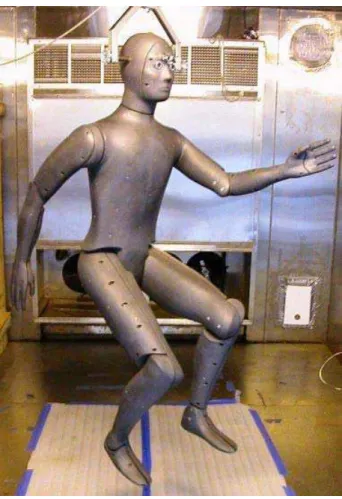
human testing, but, due to the extreme low temperatures experienced in the Arctic, such testing is difficult to conduct on humans without encountering ethical issues. Thus, an alternative to human testing must be made viable. In Canada, thermal manikins are used to conduct such tests, but this is not a standard global practice due to difficulties in proving the comparability of manikin test to human tests. An example of a thermal manikin is shown in Figure 1 below. This is difficult to do because manikins are not standardized throughout the world, and so data produced from one manikin is not falsifiable by another. Without some way of creating a direct means of comparison between manikins, there is no way to directly compare manikin results in general with human results (Mak, 2009).
1.3 Purpose: Creating a Calibration Standard for Thermal Manikins
The design of a portable calorimeter was undertaken for the purpose of creating a calibration standard for thermal manikins. This calibration standard would create a means of comparison between manikins, which, as described in Section 1.1 – Project Background, is what is lacking for manikins to be considered as a substitute for human testing. The portable calorimeter will provide such a calibration standard because thermal manikins can be calibrated via calorimetric methods. A high-accuracy calorimeter that can be shipped to manikin users would allow them to verify that their manikin is reporting accurate data. This would validate the manikins as a means of evaluating thermal regulations for Arctic survival equipment.
1.4 Project Partners
The portable calorimeter development is part of the larger Maritime and Arctic Survival Scientific and Engineering Research Team (MASSERT) project. This project team is composed of members from the National Research Council Canada’s Institute for Ocean Technology (NRC-IOT), the Marine Institute, Memorial University, Defense Research and Development Canada (DRDC), Helly Hansen, Brock University, and SafetyNet: Centre for Occupational Health and Safety Research. The project manager is Lawrence Mak of NRC-IOT.
2.0 DISCUSSION
2.1 Portable Calorimeter Design
The purpose of the portable calorimeter is to provide a calibration reference for thermal manikins. This section will discuss the portable calorimeter and its design criteria.
2.1.1 Thermal manikins and calibration methods
Thermal manikins are measurement tools that are used to model the human thermoregulatory system. This is done through their division into thermal zones, each of which is outfitted with a heat generator and temperature sensors. The manikin is set to maintain a constant surface temperature, and the heat generators will output the necessary amount of power to maintain the specified temperature. Each manikin has a data acquisition system that communicates the amount of heat flux (W/m2) that is being output at each zone to maintain the temperature. The amount of heat required changes depending upon the amount of insulation from clothing that is on the manikin. The more insulation there is, the less heat will be required. From the communicated amount of heat flux, the insulation value of the clothing in which the manikin is dressed can be measured.
Thermal manikins must be calibrated, like all measurement tools, to ensure that they are producing accurate data. One method of doing this is via calorimetry. To be calibrated, the manikin would be placed inside the calorimeter, which is used to measure heat output, and set to operate at a certain temperature. As the
manikin outputs heat to maintain this temperature, the calorimeter environment will absorb the heat, and the amount output can be calculated based upon the measured temperature change in the calorimeter. This measured heat output is then compared to the heat output communicated by the manikin data acquisition system, and if there is a discrepancy, then the manikin is in need of calibration, assuming the calorimeter has been correctly calibrated itself.
2.1.2 Water-flow air calorimeter design
The design of the portable calorimeter is intended to be that of a water-flow air calorimeter. A simplified diagram of how a water-flow air calorimeter works is shown below in Figure 2. It is composed of an internal dry chamber in which a heat source (e.g. a thermal manikin) would be placed, a flow channel surrounding the inner chamber through which water is circulated, and an external insulated shell. The source must be placed inside the chamber so that is not in thermal contact with the walls. This is to minimize heat conduction, because the calorimeter is intended to transfer heat through primarily convection and some radiation. Achieving this will involve constructing a frame from which the heat source will be suspended in the center of the chamber. The heat from the source warms the air in chamber, and is in turn transferred to the water flowing around the chamber, carrying the heat away. In the extended system, this water would be circulated through a chiller to be returned to the same temperature as before it gained heat traveling through the calorimeter.
Figure 2: Simplified diagram of a water-flow air calorimeter
The decision to use a water-flow air calorimeter was made because the only alternative is a water-bath calorimeter. Unlike the water-flow air calorimeter, a water-bath calorimeter would require the immersion of the thermal manikin into water. It achieves the same function, but only some manikins are designed to be immersed in water; many are not.
The parameters of the water-flow air calorimeter that are used to calculate the heat (W) output by the manikin are derived from the simple calorimetric equation,
T mc
q= Δ
where q is the heat transferred away from the manikin (W), m is the mass flow rate (kg/s) of water through the channel, c is the specific heat capacity of the heat transfer medium (4.187 kJ/kg•K for water), and ΔT is the temperature difference between the inlet temperature (Tin, °C) and the outlet temperature (Tin, °C). It
should be noted that an assumption is being made for ΔT: that the differences in temperature between the inlet temperature and the environmental temperature and the outlet temperature and the environmental temperature are the same. If this assumption is not true, then a non-linear term becomes involved, and the simplified equation cannot be used.
2.1.3 Portability
The calorimeter must be portable because of manikin user concerns about the integrity of their manikins. Thermal manikins are expensive tools, some costing hundreds of thousands of dollars, and users do not want to risk damaging them during shipping if they had to be sent to a calibration lab and then shipped back. So, instead, the calorimeter itself is being designed to be portable. This will eliminate any user concerns about the integrity of their manikins. The calorimeter will be shipped to the participating laboratories to be used for calibrating their manikins, at which point it will be shipped back to IOT, where it will be recalibrated and then shipped out again. In this way, all participating manikins will be calibrated by the same reference.
2.1.4 Minimizing system error
The portable calorimeter must have a maximum error of 1% in its measurement because the calorimeter is intended to calibrate the thermal manikins to be accurate, so it must be very accurate itself. As per the portable calorimeter design specification (Boileau, 2009) in Appendix A, this translates to a total system heat loss of less than 1 W if there is to be no calibration factor, and at
most 5 W of heat loss if the heat loss is to be quantified and accounted for in the calibration equation. The error in measurement must be this low because it must have the same order of magnitude as the uncertainty in the manikin data if it is to produce a valid calibration reference. Differing laboratory set-ups and experimental procedures, as well as errors in the existing manikin calibration can cause this uncertainty. All of these sources of error must be identified and minimized.
To ensure that the heat loss (error) in the system is kept minimal, the calorimeter must be adequately insulated. This must be balanced with the physical limitations on the size of the system, because the calorimeter has to be designed to fit into the environmental chambers of the participating laboratories. So, an optimal amount of insulation must be determined based on design information collected from the laboratories.
2.2 Portable Calorimeter Design Information Gathering
To inform the design of the portable calorimeter and determine constraints on the physical dimensions, power capacity, and electrical requirements, it was necessary to contact the users of thermal manikins that would be participating in the calibration procedure. 22 individuals were contacted at 20 different laboratories and organizations, three of which were manufacturers, in 11 different countries. At the writing of this report, responses had been received from 10 of those contacted, of which five were manikin users, two were manufacturers, and
three were found not to be involved in manikin testing. They were informed of the purpose of the portable calorimeter project, and provided with a survey sheet (see Appendix B) to be filled out with information regarding their manikin and facility specifications.
2.2.1 Purpose of information gathered
The information requested about their manikins was the model and manufacturer, the physical dimensions and mass, the degree of articulation in the manikin body, certain specifics about functionality, such as how it is supported and transported, the manikin power requirements (W), the number of thermal zones, and the time required for the manikin to reach the steady state of the set temperature. This information is necessary because the manikins with the largest dimensions and mass will define the dimensions of the internal calorimeter chamber and the amount of weight the system must support. The articulation and functionality of the manikins will define if additional support systems must be designed for placing manikins in the calorimeter and how flexible these must be to accommodate manikins with little articulation. The power requirements will define maximum amount of heat the calorimeter must be designed to be able to cool. The time to reach steady state will define the length of the experiments, and thus will have an impact on the accuracy of the system, as longer experiments allow for more data to be gathered.
The information requested about the testing facilities was the physical dimensions of the entrance, the amount of overhead clearance within the chamber, the accuracy of the environmental control for the chamber, the cooling capacity of the chamber (not included in the survey; requested later), the voltage and cycles of the outlets, and any lifting apparatus present. This information is necessary because the dimensions of the smallest entrance will define the outer dimensions of the calorimeter, since it must be able to fit into all chambers. The amount of overhead clearance will define the orientation of the calorimeter; i.e. whether its largest dimensions will be its height or as its length when it is in its operating position. The accuracy of the environmental control for the chamber will define the accuracy of the experiments conducted in the chamber, as the error in the calorimeter system is affected greatly by the difference in temperature between the environmental temperature and the inlet and outlet water temperature, as well as the uncertainty in that temperature. The cooling capacity (W) of the chambers will define the maximum operating power of the system, as the chambers must be able to maintain a constant temperature against the heat being output by the calorimeter system. The voltage (V) and cycles (Hz) of the outlets in the chamber will define the range of electrical connections that must be included in the calorimeter so that it will be compatible globally. The presence of a lifting apparatus will define how the manikin is loaded into the calorimeter.
2.2.2 Thermal manikin database
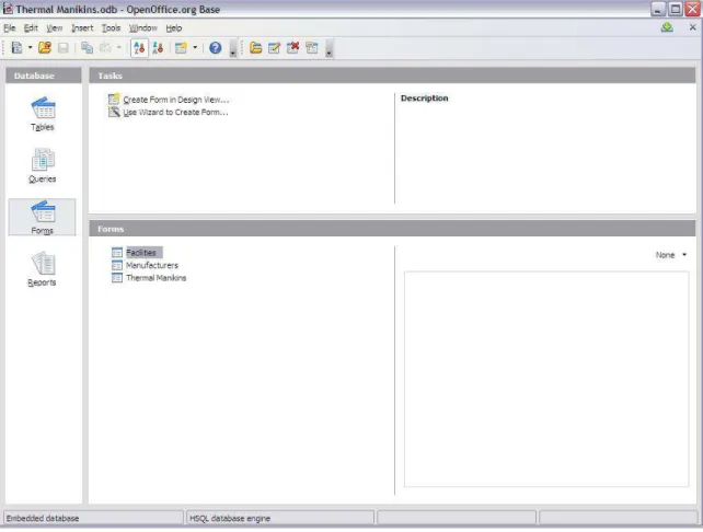
The information provided by the surveyed laboratories is being gathered into a database designed in OpenOffice.org Base. A screenshot of this thermal manikin database is shown below in Figure 3.
Figure 3: Screenshot of the thermal manikin database in OpenOffice.org Base
This database, when completed, will contain all of the necessary information described in Section 2.2.1. The purpose of incorporating it into a database is to facilitate the searching of the data, and to allow for reports to be quickly created that present the key data that will define the constraints of the portable calorimeter.
2.3 Portable Calorimeter Prototype
This section will discuss the purpose and design of a scale model prototype for the portable calorimeter. It will also discuss the proof-of-concept experiment being conducted with this prototype.
2.3.1 Purpose and design
It was determined that it would be necessary to have a method of evaluating the evenness of the cooling pattern resulting from different configurations of the water-flow channel in the portable calorimeter. It is necessary to have an even cooling pattern because this ensures that all of the heat output from the manikin is being captured. If there were different cold and hot zones, it would be indicative of a lack of thermal transfer in certain areas. The suggested channel configurations were to use either an open space between the two chambers, a space divided into a number of channels by flow dividers lining the sides of the inner chamber, or a conduit of tubing or piping wrapped around the inner chamber. To evaluate these then, a scale model prototype of the portable calorimeter was constructed to model the various flow channel configurations. The specification and design drawings for this prototype can be found in Appendix C. The prototype is comprised of two rectangular aluminum chambers dimensioned to fit together as pictured below in Figure 4. The inner chamber is set inside the outer chamber so there is a uniform space on all sides. The two chambers have lids that are bolted onto a flange/gasket assembly to form a watertight seal. There are four positions that have been tapped to receive a
hose-barb pipe-fitting; two are on the outer chamber lid, one is at the top of one side of the outer chamber, and the other is at the bottom of the side opposite the latter pipe-fitting at the top. The latter position always has a hose-barb fit into it, while the former three will only have one hose-barb in any one of them at a time, while the other two are sealed with plugs.
Figure 4: Portable calorimeter prototype with chamber lids removed
2.3.2 Experimentation
An experiment was developed to determine whether each water-flow channel configuration would produce an even cooling pattern. The prototype is connected to a water tap – one that has been measured for uniformity of water temperature – using tubing fitted to a hose-barb at the top of the prototype, and the water is cycled back to the drain via another tube fitted to the hose-barb at the bottom. The prototype is then suspended by a rope from a crane, as pictured below in Figure 5, so that it is not in direct thermal contact with its surroundings. This
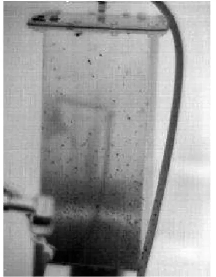
minimizes heat conduction, which, as described in Section 2.1.2, is an unwanted mode of thermal transfer in the calorimeter. It also makes it easy to photograph the prototype with a thermal camera from multiple angles during experimentation. The photographs will be taken of all sides at set intervals to determine how the cooling pattern changes over time, and if it approaches a completely even pattern. The thermal images produced by the camera, like the one shown below in Figure 6, are the primary means of evaluating the evenness of the cooling pattern caused by flowing water through the channel in the prototype. As can be seen in the picture, the prototype is colder at the bottom than at the top. The ideal pattern would be a uniform colour across the prototype. Efforts are also being made to place a temperature data logger in the inner chamber to determine when the temperature there reaches equilibrium.
Figure 5: Prototype experimental setup Figure 6: Thermal image of prototype during experiment
The different water-flow channel configurations will be implemented by first leaving the space between the chambers free of all obstructions other than the necessary standoff pegs. Next, strips of acrylic will be glued in the space in even intervals to act as flow deflectors to model the presence a number of flow channels. Finally, the inner chamber will be wrapped in tubing or piping, and water will be flowed through the tube/pipe. In this way, it will be determined which configuration produces the most even cooling pattern.
It should be noted that the design of this prototype inverts the thermal transfer direction from what will be the direction in the final calorimeter design. This is so because the final design must have an even cooling pattern at the walls of the inner chamber, but the prototype can only be photographed from the outside. So, here the inner chamber is equivalent to the outer shell of the calorimeter, and it acts as a perfect insulator because it is a finite space. The outer chamber then acts as the inner chamber of the calorimeter, and the heat source is the room environment. The outer chamber will be at room temperature initially, but it will ideally be cooled at all points to the temperature of the water flowing through it.
3.0 CONCLUSION
It is necessary to complete the design, fabrication, and testing of the portable calorimeter so that it can begin being used as a standard calibration tool for thermal manikins. There are already obvious advantages to using manikins over human testing, such as repeatability of results, low cost, and lack of ethical concerns, but before manikin testing can become ubiquitous, they must be rigorously established as a viable substitute for humans. This portable calorimeter will provide the necessary means of comparison between manikins so that they can be rigorously tested. This will then facilitate the development of safety and survival equipment standards for marine operations in the Arctic.
For the portable calorimeter to be finished the collection and analysis of the necessary design information must be completed and from this the final constraints on the design must be established. The experimentation of the water-flow channel scale model prototype must also be completed to determine what channel configuration should be used for cooling. Once the design has been completed and the calorimeter built, it must be tested once at IOT, and then again at another laboratory. The results will be compared, and if the calorimeter is determined to be calibrated correctly and reporting accurate results, it will be begin being shipped to participating laboratories for the purpose of calibrating and standardizing thermal manikins world-wide.
4.0 REFERENCES
Boileau, R. 2009. Institute for Ocean Technology, Personal Correspondence.
Boileau, R. 2009. Portable Calorimeter Specification. Unpublished internal NRC-IOT document. 2009-08-13 port cal spec (3).pdf.
Mak, L, 2009. Institute for Ocean Technology, Personal Correspondence.
Mak, L., et al. 2009. Thermal Requirements for Surviving a Mass Rescue in the Arctic. Unpublished project proposal.
Webb, P., J. Annis, and S. Troutman. 1972. Human calorimetry with a water- cooled garment. Journal of Applied Psychology 32 (3): 412-418.
Appendix A:
Appendix B:
Appendix C:
See the following drawings on record with the IOT design office:
• Portable Calorimeter Prototype Outer Chamber – 422296J01 • Portable Calorimeter Prototype Outer Chamber Lid – 422296J02 • Portable Calorimeter Prototype Inner Chamber – 422296J03 • Portable Calorimeter Prototype Inner Chamber Lid – 422296J04


![Dalitz plot analysis of B[subscript 0][subscript s] → [bar overD][superscript 0] K[superscript −] π[superscript +] Decays](data:image/gif;base64,R0lGODlhAQABAIAAAP///wAAACH5BAEAAAAALAAAAAABAAEAAAICRAEAOw==)