HAL Id: in2p3-01044682
http://hal.in2p3.fr/in2p3-01044682
Submitted on 13 Feb 2015HAL is a multi-disciplinary open access archive for the deposit and dissemination of sci-entific research documents, whether they are pub-lished or not. The documents may come from teaching and research institutions in France or abroad, or from public or private research centers.
L’archive ouverte pluridisciplinaire HAL, est destinée au dépôt et à la diffusion de documents scientifiques de niveau recherche, publiés ou non, émanant des établissements d’enseignement et de recherche français ou étrangers, des laboratoires publics ou privés.
SPIRAL2 Bunch Extension Monitor
R. Revenko, J.L. Vignet
To cite this version:
R. Revenko, J.L. Vignet. SPIRAL2 Bunch Extension Monitor. 27th Linear Accelerator Conference -LINAC14, Aug 2014, Genève, Switzerland. pp.824-826. �in2p3-01044682�
SPIRAL2 BUNCH EXTENSION MONITOR
R. Revenko, J-L. Vignet, GANIL, Caen, France
Abstract
Superconducting linacs require beam diagnostics to quantify the time extension of the bunch for a proper beam adaptation. Bunch extension monitor (BEM) should provide measurements with required resolution and minimal disturbance of beam properties, have a broad dynamic range of beam intensity and should be easy to use for accelerator routine operation. The design of BEM should take into account operation at the vicinity of cryomodules and satisfy imposed requirements for this. BEM measures the x-rays resulting of the bunch interaction with a tungsten wire. Developed prototype of detector was successfully tested with ions beams. Test for detector background conditions at vicinity of cryomodule was carried out and results are presented.
INTRODUCTION
The SPIRAL2 project [1] is based on a multi-beam LINAC driver in order to allow both ISOL and low-energy in-flight techniques to produce RIB. A superconducting light/heavy-ion LINAC with an acceleration potential of about 40 MV capable of accelerating 5 mA deuterons up to 40 MeV and 1 mA heavy ions up to 14.5 MeV/u is used to bombard both thick and thin targets. These beams could be used for the production of intense radioactive beams. The production of high intensity RIB of neutron-rich nuclei will be based on fission of uranium target induced by neutrons, obtained from a deuteron beam impinging on a graphite converter (up to 1014 fissions/s) or by a direct irradiation
with a deuteron, 3He or 4He beam.
The LINAC [2] consists of two families of superconducting cavities placed in 12 cryomodules of type A and 7 cryomodules of type B where cryomodules are separated by 20 warm sections equipped by two quadrupoles and one diagnostic box. The LINAC is operated at frequency 88,0525 MHz that corresponded to 11.26 ns period between neighbour bunches. Expected phase extension is 60˚ (±2σ) or ~1,6 nsec for bunch length. The LINAC can operate at continuous or pulsed mode with period of macropulse varied at range from 100 µsec to 1 sec.
Proper LINAC adjustment is necessary for obtaining maximal intensity and luminosity on the target. Phase synchronization for each acceleration section is necessary and information about spatial beam distribution is required. While the beam transverse profile will be measured by pick up monitors (BPM) information about bunch longitudinal distribution will be obtained using a bunch extension monitor (BEM). These diagnostic detectors will be installed in firsts five warm sections placed in gaps between superconducting acceleration cavities.
BEM DESCRIPTION
The bunch extension monitor [3] is a non-interceptive beam diagnostic detector. Principe of operation is based on registration of photons emitted from thin tungsten wire placed into the beam of LINAC. Comparing to beam diagnostics based on secondary electrons emission the BEM is not using applied potential on the wire and thus measurements do not produce distortion of the beam optics. Also all BEM components should meet to UHV requirements due to operation under vacuum below 10 8 mbar and satisfy to required cleanness conditions to
prevent cavity pollution.
BEM Design
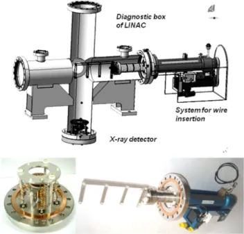
The BEM mechanics consists of two parts: x-ray detector and system for wire insertion. These parts are mounted two flanges of diagnostic box of warm section (see Fig. 1).
Figure 1: General view of BEM installation on diagnostic box of LINAC (top) and photo of BEM components (bottom).
The system for wire insertion permits to displace and position the tungsten wire into the beam with precision better than 100 µm. It is equipped with three wire holders on stainless steel frame. Tungsten wires of 150 microns diameter are placed on diagonal inside each holder. Wires of neighbouring BEMs are placed in perpendicular
© 2014 CC-BY -3.0 and by the respecti v e authors
directions for minimization of influence one BEM to another. Design with three wire holders allows fast replacing the wire if one will be damaged.
The frame with wire holders is fixed through isolator on a rod of linear actuator which has movement range of 178 mm. The wire insertion system is driven by brushless motor of mounted on external side. The brushless motor is a component of Siemens SIMATIC 110 positioning system. The system for wire insertion has option for current pick up measurements. Conductive frame with wires holders is electrically isolated from other mechanical pieces and is connected through vacuum feedthrough and cable to electronics for current measurements.
The X-ray detector of BEM is used for registration of photons emitted from the wire. It is placed at distance 240mm from beam axis on bottom flange of diagnostic box. Two microchannel plates Hamamatsu F1551 ( 18mm) with 12 µm channels are used. MCP has electrodes covered by Inconel alloy and no other converters for photons were used. MCPs are assembled in chevron configuration with 3 mm gap between plates to increase amplitudes of output signal. Each MCP can
provide gain up to 104 at 1 kV applied voltage. For
providing of short output pulse detector has fast readout with coaxial anode that has matched on 50 Ohms impedance. Anode is connected to N-type connector on CF100 flange. Entrance of the first MCP is covered by copper collimator with solid angle 2×10⁻⁴sr to register
photons emitted directly from the wire.
Aluminium deflecting foil with positive potential is placed in front of detector. It is used to eliminate background signals due to ions coming from residual gas ionization. Foil has 10 microns thickness and does not produce significant x-ray absorption.
BEM Working Principle
Due to interaction of beam ions with electron shell of tungsten atoms ionization can occur. Electrons from inner shell can be knocked out and replaced with electron from outer shells with x-ray emission. Obviously, these photons have strictly defined energies and formed characteristic x-ray spectrum which are unique for each element.
Characteristic x-rays have isotropic emission from tungsten wire and are registered by x-ray detector of BEM that based on micro channel plate design (MCP). Photons interact with material of MCP channels and produce secondary emissions electrons due to photoelectric effect. These electrons are multiplied in chevron assembled MCPs with gain coefficient 107÷108 and are collected with fast
readout anode. Typical output pulses have about 1 nsec duration with 400 psec risetime and amplitudes of few hundreds of mV.
Figure 2: Waveforms of output pulses direct from x-ray detector (left) and after passing of long cable to electronics (right) (500 psec/div and 100mV/div).
All components of BEM electronics are placed in technical room and output signal from the detector is transmitted from LINAC tunnel through 55 meters length coaxial cable [see Fig. 2]. The output pulse has insignificantly (up to 500 psec) degradation of risetime and amplitude attenuation by factor 2.
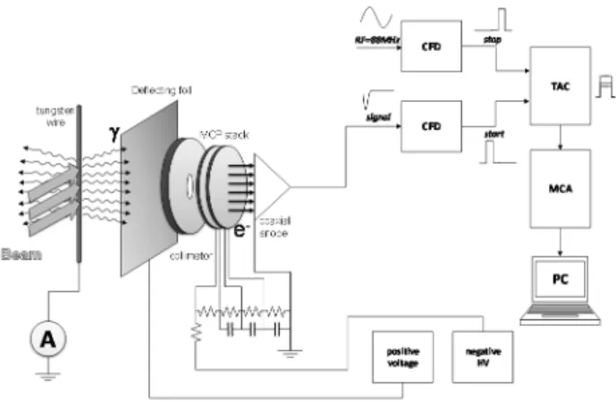
Figure 3: Schema of BEM electronics.
Scheme of readout electronics for BEM is presented in Fig. 3. Output signal from this cable is amplified by fast amplifier ORTEC FTA820 before to go to constant fraction discriminator ORTEC 935. Output signal of CFD is used as “start” trigger for time-to-amplitude converter ORTEC 566 while “stop” trigger is provided by linac rf. Outputs signals from TAC are measured by multichannel analyser CANBERRA Multiport II. A distribution of TAC amplitudes gives information about average extension of bunch.
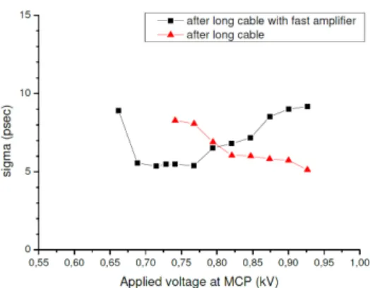
X-ray source of 55Fe was used for estimation of readout
electronics time resolution. Output signal from the detector prototype was transmitted through 74 meters length RG213 coaxial cable and then split in two signals sent to CFD inputs. One of the signals was previously delayed by 10 ns and used as "stop" trigger. Measurements were performed with and without the fast amplifier at different values of MCP gain (see Fig. 4).
© 2014 CC-BY -3.0 and by the respecti v e authors
Figure 4: Time resolution of BEM readout electronics versus MCP gain
The prototype of x-ray detector was successfully tested with ion beams at GANIL. One of measured bunch
longitudinal profile obtained for 18O+4 ions with
0,55 MeV/A energy is presented on Fig. 5
Figure 5: Measured bunch profile for 18O+4 beam
BEM TEST AT CRYOMODULE VICINITY
The aim of this test was to estimate BEM background due to operation next to a superconducting cavity. For this reason BEM was installed into warm section connected to a cryomodule to be as close as possible to the real conditions.Figure 6: Installation of cryomodule type B and warm section on testing bench
The test was performed at IPN Orsay on special testing bench using cryomodule type B (see Fig. 6). This cryomodule has two superconducting cavities with liquid-helium cooling. Differences between two types of cryomodules are number of cavities per module and their dimensions.
Preparation and Installation
All components connected to cavity volume have been cleaned previously. Prototype of BEM was disassembled and all parts have been passed special cleaning procedures. Afterwards all parts were dried and assembled under laminar flow inside an ISO4 class clean room.
Two portable clean rooms were used for installation. The first portable clean room, of ISO 5 class with laminar flow was mounted over the warm section and used to connect cryomodule. Another portable clean room of ISO 7 class was used as buffer area between ISO 5 clean room and environment. Cleaning of adjacent parts was done before performing connection of warm section to the flange of cryomodule. More cleaning and monitoring of particle contamination level was carried out before BEM installation. Imposed requirements for dust contamination provided total absence of dust particles of 5 microns and more, and no more than 100 particles with dimension 0.5 micron around the area of BEM installation.
Measurements
The testing bench with cryomodule was placed inside a shielded casemate with concrete walls about 1 meter thick. Level of x-rays emission generated by cavity was monitored during all the time of operation and a few x-ray probes installed near the cryomodule. Two dose monitors Canberra BARA 31 with external low dose rate probe SFDE were used. These probes are Geiger-Müller detectors and have a measurement range from 3 µSv/h to 100 mSv/h and perform registration of x-rays within energy range from 40 keV to 1.25 MeV. Probes were mounted on beam axis against the flange of the warm section and at 90 degrees from beam axis against the cryomodule.
Figure 7: Spectrum of x-ray emission at 6 MV/m of accelerating field gradient
Another portable spectrometer with NaI crystal was installed at 2 meters from cavity and was used for measurements of x-rays spectra (see Fig. 7). After subtracting of background noise, a maximal energy of emitted photons from cavity was estimated. At nominal gradient value (6.5 MV/m) the maximal energies of x-ray are close to 1000 keV.
0 5 10 15 20 25 30 35 40 45 50 0 20 40 60 80 100 C o u n ts Time (nsec) © 2014 CC-BY -3.0 and by the respecti v e authors
Superconducting cavities of tested cryomodule had different levels of field emission. The cavity situated closest to the warm section (MB03) had about zero field emission while the other cavity (MB01) produced a dose about 100 Sv/h at 6,5 MV/m of accelerating gradient. The test was carried out with alternately operated cavities. Implemented scheme of electronics was the same as for time resolution measurements but measured parameter s count rate from detector at different values of applied accelerating field.
Two series of measurements were done for each value of gradient field: without and with inserted wire. The measurement without wire allows estimating a general background for x-ray detector while the measurement with inserted wire gives information about process of x-ray fluorescence, which has more crucial sense for operation of BEM. X-rays propagating in a direction of beam axis with energies more than potential of ionization for tungsten can produce secondary x-rays. These x-rays are identical to x-rays produced due to ionization by beam ions.
Results of the Test
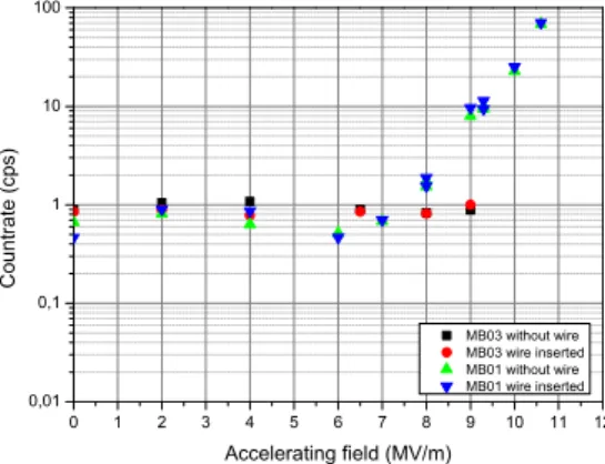
Measurements were started at 2 MV/m of accelerating field gradient and have been done up to 11 MV/m. In the range up to 2 MV/m before a multipacting barrier has been crossed (1.2 MV/m), a high x-ray background has been observed and thus measurements were not carried out in this range due to safety reasons for detector. Nominal operation value of gradient field for LINAC cavities is 6.5 MV/m. 0 1 2 3 4 5 6 7 8 9 10 11 12 0,01 0,1 1 10 100 Co un tr at e ( cps) Accelerating field (MV/m) MB03 without wire MB03 wire inserted MB01 without wire MB01 wire inserted
Figure 8: Background count rate of BEM detector versus applied gradient of accelerating field
As results shown in Fig. 8, x-ray emission from cavity was negligibly up to 7 MV/m (including nominal value 6,5 MV/m) and does not enhance the detector background. Only for MB01 cavity which has higher emission rate the x-ray emission increases after 7 MV/m varies with applied accelerating field. These results are also confirmed by measurements with dose probes.
Comparison of measurements performed with inserted wire and without it (see Fig. 9) shows absence of
significant emissions of x-rays with high energies along beam axis. It is also indirectly confirmed by results of dose measurements with dose probes, but in this case should be taken into account corrections for solid angles and absorptions. Growth of secondary x-ray emission from the wire due to process of x-ray fluorescence was only observed for cavity MB01 after exceeding 9MV/m for field gradient. 0 1 2 3 4 5 6 7 8 9 10 11 12 -1 0 1 2 3 MB03 MB01 Co un tr at e ( cps) Accelerating field (MV/m)
Figure 9: Difference between count rates measurements with and without wire insertion.
Comparisons of cavities solid angles were done for interpretation of obtained data for the case of cryomodule type A. Rough assumption that emission occurs at whole volume of cavity was taken and solid angles between detector and cavity volume were calculated. The estimated solid angle can be found as angle subtended by a cylinder (superconducting cavity) at a point (x-ray detector). The calculations were performed for cavity of cryomodules type A and both cavities of cryomodule type B. An analytical formula for this calculation was taken from work [4]. Obtained values for solid angles give ratios 0.680 or 1.565 between the cavity of cryomodule type A and the nearest or distant cavities of cryomodule type B respectively.
Thus by making a comparison of count rates obtained during the test for cavities of cryomodule type B we can made rough estimation of expected background from cavity of cryomodule type A in the same conditions of x-ray emission.
CONCLUSION
The bunch extension monitor for LINAC of SPIRAL2 was developed and preliminary tested on the ions beam. The values of time resolution for readout electronics was estimated and are close to 5 psec.
The emission of x-ray fluxes from rf cavities can limit the performance of ionization sensitive detectors placed near them. It is very complicated to assess in advance a field emission from cavity since cavities operate under a variety of conditions which are individually for each cavity (design, treatments of surface preparation and grade of its ©
2014 CC-BY -3.0 and by the respecti v e authors
contamination). Performing of direct measurements is most preferable.
The results of this test have been proven possibility of operation BEM close to a cryomodule. A background count rate generated by cavity of cryomodule after crossing of multipacting barrier is negligibly small and does not produce significant contribution to the detector total background. This value remains at 1-2 cps up to 7 MV/m. Comparison of measurements with inserted wire and without shows lack of influence on the number of registered events. Thus a production of secondary x-rays from the wire due to process of x-ray fluorescence is very insignificant and will not affect on the bunch extension measurements.
It is expected that background condition in case of cavity type A will be close to conditions of this test.
REFERENCES
[1] SPIRAL2 project, http://www.ganil-spiral2.eu/ [2] D. Uriot et al., “Configuration de base du LINAC
supraconducteur de SPIRAL2 V2.0”, Référence Spiral 2 I-013103/1 (2008).
[3] R. Revenko et al., “Bunch Extension Monitor for LINAC of SPIRAL2 facility”, Proc. IBIC13, Oxford, UK, (2013), WEPC20, http://jacow.org/
[4] S. Tryka, “Calculation of the solid angle subtended by a cylinder at a point” Applied Radiation and Isotopes 70 (2012) 2466-2470 © 2014 CC-BY -3.0 and by the respecti v e authors