HAL Id: hal-01824958
https://hal.archives-ouvertes.fr/hal-01824958
Submitted on 27 Jun 2018
HAL is a multi-disciplinary open access
archive for the deposit and dissemination of
sci-entific research documents, whether they are
pub-lished or not. The documents may come from
teaching and research institutions in France or
abroad, or from public or private research centers.
L’archive ouverte pluridisciplinaire HAL, est
destinée au dépôt et à la diffusion de documents
scientifiques de niveau recherche, publiés ou non,
émanant des établissements d’enseignement et de
recherche français ou étrangers, des laboratoires
publics ou privés.
Enhanced hot-electron production and strong-shock
generation in hydrogen-rich ablators for shock ignition
W. Theobald, A. Bose, R. Yan, R. Betti, M. Lafon, D. Mangino, A.
Christopherson, C. Stoeckl, W. Seka, W. Shang, et al.
To cite this version:
W. Theobald, A. Bose, R. Yan, R. Betti, M. Lafon, et al.. Enhanced hot-electron production and
strong-shock generation in hydrogen-rich ablators for shock ignition. Physics of Plasmas, American
Institute of Physics, 2017, 24 (12), pp.120702. �10.1063/1.4986797�. �hal-01824958�
Department of Mechanical Engineering, University of Rochester, Rochester, NY
5
Department of Modern Mechanics, University of Science and Technology of China, Hefei, Peoples Republic of China
6CEA, DAM, DIF, F-91297 Arpajon, France 7
Lawrence Livermore National Laboratory, Livermore, CA
8
Centre Lasers Intenses et Applications, CELIA, Universit´e Bordeaux CEA-CNRS, Talence, France
9
University of California-San Diego, La Jolla, CA and
10
General Atomics, San Diego, CA, USA (Dated: October 31, 2017)
Experiments were performed with CH, Be, C, and SiO2 ablators interacting with high-intensity
UV laser radiation (5×10¹⁵ W/cm2, λ = 351 nm) to determine the optimum material for
hot-electron production and strong-shock generation. Significantly more hot hot-electrons are produced in CH (up to ∼13% instantaneous conversion efficiency), while the amount is a factor of ∼2 to 3 lower in the other ablators. A larger hot-electron fraction is correlated with a higher effective ablation pressure. The higher conversion efficiency in CH is attributed to stronger damping of ion-acoustic waves because of the presence of light H ions.
Generating strong shocks up to several hundred megabars allows one to explore plasma and material properties at the most-extreme conditions of energy den-sity. It also enables one to develop two-step inertial con-finement fusion (ICF) schemes, where ignition is sepa-rated from the main compression of the thermonuclear fuel. A promising two-step ignition scheme is shock ig-nition (SI) [1–4], where igig-nition is triggered by a strong shock launched at the end of the implosion and driven by a pressure above ∼300 Mbar. Detailed reviews of the current status and physics issues for SI are found in Refs. [5–7]. One of the most critical issues is the high UV laser intensity of 5×10¹⁵ to 1×10¹⁶ W/cm2
required by the ignitor spike pulse. The spike will ex-cite parametric laser–plasma instabilities (LPI’s) in the hot plasma corona surrounding the imploding capsule, thereby transferring a significant amount of laser energy to hot electrons. Recent work [8–10] demonstrated that hot electrons can enhance the shock pressure. It is still an open question whether they might preheat a SI target [11] or if the benefits prevail because the areal density is large enough to stop them in the shell and augment the shock strength [12, 13]. Another concern pertains to the energy coupling. The spike pulse must couple sufficient energy to the target in order to generate a strong-enough shock. LPI’s may reduce the coupling efficiency and pre-vent the seed shock pressure from reaching the required magnitude.
Directly measuring the pressure at these high intensi-ties is nearly impossible, so it must be instead inferred indirectly. Experiments in planar geometry at the LULI
[14], Omega [15], and PALS [16] Laser Facilities have in-ferred ablation pressures in the range of ∼40 to 90 Mbar, which were limited by lateral heat flow from the laser spots in the planar geometries. The lateral transport was suppressed with the development of a new platform [17, 18] that applies spherical targets and x-ray diagnos-tics. It allows one to evaluate the pressure at SI–relevant laser intensities. The laser launches into the solid target an inwardly propagating shock wave that converges at the center, generating a short x-ray flash that is measured with a time-resolved diagnostic. Several experiments es-tablished this scheme as a reliable platform using a vari-ety of laser energies, pulse shapes, and target diameters [18].
There is a continuing interest in exploring new ab-lator materials in direct-drive ICF research in order to improve the hydrodynamic efficiency [19], mitigate the hot-electron production [20, 21], and suppress the Rayleigh–Taylor instability [22–24]. Recent theoretical work demonstrated an overall better performance with mid-Z ablators than plastic (CH) by suppressing the threshold of detrimental LPI while preserving the hy-drodynamic stability properties [25]. All of this work has been performed, however, at low laser intensities of up to ∼1×10¹⁵W/cm2, which is relevant for the standard
hot-spot–ignition concept but not for the spike interaction in SI.
This Letter describes for the first time that the ab-lator plays an important role at SI–relevant laser inten-sities. The experiment shows that CH produces signifi-cantly more hot electrons and stronger shocks than the
2
FIG. 1. (a) Target design consisting of an outer ablator layer of various materials and an inner Ti-doped plastic core; (b) pulse shape.
other materials. This important finding sheds light on the laser plasma–interaction physics in an intensity and plasma regime, which is insufficiently explored and might provide a path to higher energy density states in direct-drive geometry.
The experiment used 60 UV (λ = 351 nm) beams from the OMEGA laser [26] with a total energy of 22 to 26 kJ that were focused to an overlapping intensity of up to ∼5×10¹⁵ W/cm2 on the surface of a spherical solid
tar-get. The beams were equipped with small-spot phase plates [27], polarization smoothing [28], and smoothing by spectral dispersion (SSD) [29]. The single-beam in-tensity was ∼4×10¹⁴ W/cm2 for SSD on and ∼6×10¹⁴
W/cm2 for SSD off. The targets with an outer diameter (OD) of 412 to 496 µm consisted of an inner CH core that was doped with Ti with an atomic concentration of 5% and an outer ablator layer with a thickness (t) of 20 to 46 µm of a different material [Fig. 1(a)]. The outer layer was irradiated with the laser pulse shown in Fig. 1(b). A low-power prepulse of ∼1-ns duration produced a plasma corona with which the high-power part of the pulse interacted to generate the shock and the hot electrons. Four ablators (CH, Be, C, and SiO2)
with different atomic numbers (Z) were used. Table I summarizes the parameters. The shock wave collapsed in the center, resulting in a short burst of x-ray radia-tion that was detected spatially and temporally resolved with multiple x-ray framing cameras. Each framing cam-era was absolutely timed through dedicated timing shots [19, 30] with an accuracy of 30 ps. Time-resolved and time-integrated hard x-ray measurements provide a char-acterization of the hot-electron population (hot-electron temperature and total energy). Details on this can be found in Ref. [18] and references therein. The output from a radiation–hydrodynamics simulation for each tar-get was used as an input for a Monte Carlo electron and photon transport code simulation (ITS 3.0) to calculate the bremsstrahlung emission for each diagnostic channel and compare it to the measurement. The hot-electron energy and temperature were varied until good agree-ment between calculations and experiagree-mental values were
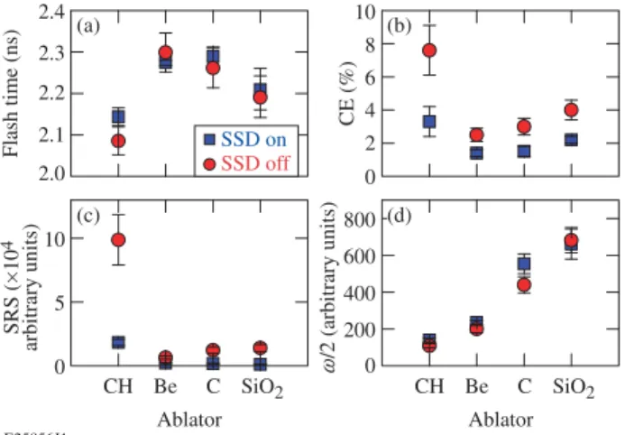
FIG. 2. (a) X-ray flash time for different ablators with smoothing by spectral dispersion (SSD) on (squares) and SSD off (circles); (b) measured time-integrated conversion efficiency (CE) of laser energy into hot-electron energy; (c) stimulated Raman scattering (SRS) backscatter signal, and (d) ω/2 signal.
achieved. The instrument response function was also modeled with the Monte Carlo code. The Monte Carlo simulation takes the material effects into account and calculates the hot-electron stopping in the compressed target and the resulting hard x-ray emission including opacity effects. Optical backscatter diagnostics mea-sured the amount of backscattered energy at the laser wavelength and provided temporally streaked spectra of the stimulated Brillouin scattering (SBS) and the stimu-lated Raman scattering (SRS). A quantity α is defined as α = 1 − E351/EL, where E351 is the measured
backscat-tered energy around the laser wavelength and EL is the
measured incident laser energy.
Figure 2(a) shows the measured flash time, which is de-fined as the occurrence of the x-ray flash relative to the start of the laser pulse, for the different ablators with SSD on (squares) and SSD off (circles) in sequence of in-creasing Z. The measured flash times were adjusted to account for differences in target size, laser energy, and t. One-dimensional (1-D) radiation–hydrodynamics sim-ulations were performed with the code LILAC [33] to analyze the dependence of the flash time on the different variables for each material. The flash times were then adjusted for an ablator thickness that resulted in a con-stant ablator mass of 20.8 µg, a laser energy of 24 kJ, and a diameter of 372 µm for the Ti doped CH part of the target to obtain a valid comparison for the different targets. The timing adjustments were between 43 ps and 10 ps for CH and smaller than 64 ps for the other mate-rials. The data show the general trend of an earlier flash with increasing Z except for CH, which produced the earliest flash. Turning SSD off advances the flash in CH by ∼70 ps while no significant effect is observed in the other materials. Figure 2(b) shows the measured
time-temperature (Ti), radial position of nc/4 (R), and density scale length (L) from radiation–hydrodynamics simulations. The
last two columns list calculated intensity thresholds for the two-plasmon decay (TPD) [31] and stimulated Raman backscatter (SRS) [32] instabilities.
integrated conversion efficiency (CE). Plastic stands out by producing by far the most hot-electrons with up to ∼2 kJ of total hot-electron energy (time-integrated CE ∼8%) when SSD was turned off. Nine and seven shots were performed for CH with SSD on and off, respectively, to prove that the observed difference is not an artifact. If CH is treated as an exception, there is the general trend of a slight increase in hot-electron production with higher Z. The inferred hot-electron temperatures lie be-tween 60 and 80 keV and are independent of the abla-tor and SSD. A higher hot-electron fraction corresponds to an earlier flash time, which indicates that hot elec-trons play a role in the shock formation and augment its strength. The experimental data provide information about the mechanism of hot-electron generation. A clear correlation between hot-electron production and the SRS backscatter signal is observed [Fig. 2(c)]. Switching SSD on significantly decreases the SRS signal in all ablators, potentially the result of the suppression of beam filamen-tation. The detected SRS wavelengths range from ∼560 to ∼680 nm, indicating that SRS is produced in a plasma region between 0.07 ne/nc and 0.20 ne/nc, where ne is
the electron density and ncis the critical density for
351-nm light. No absolute measurement of the SRS backscat-ter was available for these shots because of a calibration issue with the diagnostic. The weaker optical emission generated by electron plasma waves (EPW’s) with half the laser frequency (ω/2) increases monotonically with Z [Fig. 2(d)].
The quantity α was measured for the different ab-lators. CH produced the highest α [0.62±0.04 (SSD on), 0.71±0.03 (SSD off)] followed by SiO2 [0.60±0.04
(SSD on), 0.61±0.04 (SSD off)], C [0.60±0.04 (SSD on), 0.63±0.04 (SSD off)], and Be [0.56±0.04 for both]. En-ergy conservation requires that EL = Eabs + E351 +
ESRS + Eh, where Eabs is the absorbed energy in the
plasma, ESRS is the SRS backscattered energy, and Eh
is the hot electron energy. ESRS was not measured,
but one can argue that it msut be roughly equal to Eh. Assuming ESRS = Eh, the absorbed energy is
Eabs ≈ EL− E351− 2Eh = (α − 2CE)EL. Using, e.g.,
the measured values for CH and SSD off, the absorbed energy is EabsCH,of f ≈ 0.56EL. A very similar value of
EabsCH,on ≈ 0.55EL is obtained for SSD on, showing that
only about half of the laser energy is absorbed in the plasma. Similar values are obtained for the other mate-rials. The high value of α for CH and SSD off is a result of the large amount of SRS backscattering and hot elec-tron energy. Therefor, absorption is about equal in all the materials and for SSD on and off. The absorbed en-ergy fractions from simulations are in the range of ∼40% to 60% and are consistent with the experimental values within the error. Since only ∼5% of the absorbed energy is coupled to the hydrodynamic drive it is reasonable to conclude that small discrepancies between simulated and experimentally-inferred laser absorptions are negligible compared to the large effects of hot electron energy de-position when it comes to producing higher pressures in the target. The variation in flash time can therefore not be explained by a difference in absorbed energy but is likely the consequence of a difference in Eh.
An effective maximum ablation pressure has been in-ferred [see Fig. 3(a)] from LILAC simulations. The effect of hot electrons was taken into account by increas-ing the flux limiter [34] so that the flash time was re-covered in the simulations for each ablator material. Al-though it has been shown in Ref. [17] that the pressure increase from hot electrons may be described by an in-creased flux limiter, this simplified description does not capture important details such as slowing down, preheat, and local energy deposition. Therefore, additional sim-ulations were performed for CH and C that included a detailed hot-electron transport model, which confirmed the pressures shown in Fig. 3(a). The simulation de-tails are discussed in Ref. [17]. Briefly, the measured hot-electron fraction and temperature were used as in-put in the LILAC simulations as well as the temporal dependence of the hot-electron production. The simula-tions employed a multigroup radiation diffusion model, an equation-of-state model based on SESAME tables, flux-limited thermal transport, and a hot-electron trans-port package. A fraction of the laser energy reaching the quarter-critical surface is converted into hot electrons, assuming a single-temperature Maxwellian distribution and an isotropic emission within a 120◦ full divergence angle in the forward direction. The hot electrons are transported in straight lines into the target. The simu-lations show that the hot electrons increase the effective
4
FIG. 3. (a) Inferred effective maximum ablation pressures for the various materials for an incident laser intensity of 5×10¹⁵W/cm2. (b) Inferred time-resolved CE (red) and laser
pulse shapes (black) for two shots with CH (solid curves, shot 73648) and C (dashed curves, shot 73645). Both shots were taken with SSD off. The time resolution of CE is ∼100 ps.
maximum ablation pressure in CH by 77% and in C by 45%.
Figure 3(b) shows the inferred time-resolved CE (red) for two shots with CH (solid) and C (dashed). The black curves represent the corresponding laser pulse shapes. The onset of hot-electron production lags by ∼0.2 ns with respect to the rising edge of the laser pulse. This is ex-plained by a strong SBS backscatter spike with a width of ∼0.2 ns upon the arrival of the main pulse, which re-duces temporarily the laser intensity around nc/4 below
the thresholds of the SRS and two-plasmon–decay (TPD) instabilities. In addition, the change in temperature and density scale length in this region also directly affects the LPI thresholds. LILAC simulations show that a plateau in the velocity profile develops in the region be-tween nc/10 and nc/4, which promotes a high SBS gain
during this time. Averaged over the laser pulse shape and over the full target sphere, SBS scatters back ∼ 2 − 3% of the laser energy for CH, while this fraction is below 2% for the other ablators. A comparison of the simula-tions of the two shots shown in Fig. 3(b) reveals that at the time of the observed SBS spike, there is a difference in the flow velocity gradient of both materials. The ve-locity profile for CH is much shallower than for C. This probably caused a higher SBS gain in CH than in C. Time-resolved measurements of the SRS backscattering appear closely correlated with the hot-electron produc-tion. The time-resolved CE is based on the measured time-resolved hard x-ray emission [35] in the photon en-ergy range between 50 and 100 keV. It is assumed that the instantaneous amount of hot electrons is proportional to the instantaneous hard x-ray emission and that the time-integrated CE equals the measured time-integrated values [see Fig. 2(b)]. The CE reached 13±2% and 4±1% in CH and C, respectively, during the second half of the high-intensity pulse, while the time-integrated CE over the entire pulse, including the laser energy when no hot electrons were generated, yielded 9±1% and 3±1%, re-spectively, for these shots.
Plasma parameters such as the electron temperature
(Te) and the density scale length (L) play an important
role in the development of LPI. Table I provides the rel-evant coronal plasma parameters from LILAC simula-tions of the different materials at the nc/4 position and
the calculated threshold intensities for TPD and SRS. Slight differences in the plasma parameters and the cal-culated threshold intensities are observed between ma-terials. First, threshold intensities for SRS are about a factor of 2 lower than for TPD for all materials, which ex-plains why SRS is the dominant hot-electron production mechanism at these high Te’s. Second, SRS thresholds
are the same, which suggests that from a hydrodynamic point of view, no difference in hot-electron production for different materials is expected. This is in contrast to the experiment and points to a different cause. Coronal conditions of a full-scale SI target have been calculated at the nc/4 point for a polar-driven shock-ignition design
for the National Ignition Facility [13]. At the peak of the laser spike values of Te= 8.5 keV and L = 450 um were
calculated, which show that in the OMEGA experiment the temperatures are a factor of ∼2 lower and L is a factor of ∼4 shorter compared to an ignition target.
Cross-beam energy transfer (CBET) can limit the ab-lation pressure in direct-drive implosions. CBET de-pends on such parameters as the laser spot size relative to the target size, the spectrum of the laser beams, and the damping of ion-acoustic waves (IAW’s). Experiments with imploding thin CH shells on OMEGA at an inten-sity of 5×10¹⁴ W/cm2 studied the effect of the beam size for ratios of laser-spot radius to target radius from R = 1.1 to 0.5 (Ref. [36]). The experiments reported here employed solid targets with R = 1 for SSD on and R = 0.85 for SSD off, assuming an average of the ma-jor and minor axes of the elliptical focus profiles and a standard target radius of 215 µm. Based on the smaller ratio for SSD off, we would expect a reduction in CBET and a corresponding increase in hydrodynamic efficiency. The experiments indicate that the variation in beam size due to SSD does not play a role. With the exception of CH, which has the highest hot-electron production, the flash time [see Fig. 2(a)] is not influenced by SSD. SSD increased the spectral bandwidth to ∼1 ˚A. Previous ex-periments and simulations indicate that this width is not sufficient to affect CBET [37]. The damping rates are significantly higher in CH than in C (see below); there-fore CBET should be less effective in CH. Although it cannot be ruled out that CBET mitigation does play a role in CH, the increased coupled drive energy in CH is believed to be mainly the result of an increased coupling of hot electrons. It has been demonstrated in Ref. [17] that hot electrons with a total energy of ∼2 kJ play an important role in the shock formation in these experi-ments. Note that the total internal and kinetic energy supplied to the imploding target is ∼0.6 kJ (∼5% hy-droefficiency). Therefore ∼2 kJ of hot-electron energy is sufficient to significantly affect the target dynamics.
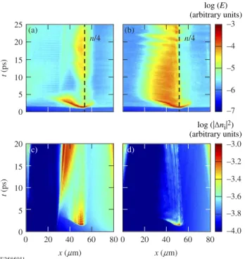
FIG. 4. Calculated longitudinal electric-field strength versus time and space (laser propagates from left to right) for (a) C and (b) CH and calculated ion-acoustic wave level for (c) C and (d) CH. The quantities were averaged over the transversal space coordinate and rendered on a logarithmic scale. The C simulation used a CH layer in the underdense portion, and the pure C layer starts at x = 30 µm.
The experiments demonstrate significant differences between CH and C, indicating that the H species plays an important role in the LPI. Other experiments that are relevant for indirect drive using low-density (ne/nc ∼
0.1), high-Z Xe plasmas that were doped with low-Z impurity (C5H12) have demonstrated an enhanced SRS
reflectivity with higher impurity concentration [38, 39]. The increased SRS reflectivity has been linked to an in-creased damping of IAW’s, which is especially high for plasmas containing H [40]; however, no hot-electron mea-surements were reported [38–40]. To elucidate the SRS physics of this experiment, 2-D particle-in-cell (PIC) sim-ulations were performed using the code OSIRIS [41] by comparing simulations with and without H in the vicin-ity of nc/4. A simulation with CH was compared to one
where H was removed in the vicinity of nc/4 (ne > 0.2
nc). These simulations were designed to identify
differ-ences in the fundamental physics of SRS caused by the presence of H. A boundary with matched density between CH in the underdense region and pure C in the higher-density region ensured that equal conditions are created for the laser pulse propagating through the underdense plasma. The input parameters were obtained from a radiation–hydrodynamics simulation for a CH shot eval-uated at 1.5 ns, when peak hot-electron production was observed. The PIC simulations assumed the same initial
both time and space. The effect of SSD was not taken into account in the simulation.
Figures 4(a) and 4(b) show the calculated longitudinal electric-field strength from EPW versus time and laser propagation direction for C and CH, respectively. Dis-tinct differences in the fields are observed. The electro-magnetic wave excites strong EPW over a large region in CH compared to C. The wave modes survive longer in CH and couple better with thermal electrons because of a larger k vector. Determined by the phase-matching condition and the dispersion relations, the EPW’s at the lower-density region have larger k. These large-k modes can accelerate thermal electrons more efficiently since their phase velocity is closer to the electron thermal ve-locity than the small-k modes close to nc/4 (Ref. [42]).
Figures 4(c) and 4(d) compare the calculated signal level of IAW’s, showing a stronger damping in CH compared to C because of the presence of light H ions. The Landau damping rates [43] were calculated for plasma conditions Te= 4 keV, Ti= 0.8 keV, k=2k0for CH and C, where k
and k0are the absolute values of the IAW and the laser
wave vectors. At 0.25nc, γ = 7.4 × 10⁻⁴ω0(CH) and γ =
2.2 × 10⁻⁵ω0 (C), where ω0 is the laser frequency, while
for a lower density of 0.12nc the calculations yield γ =
5.8 × 10⁻⁴ω0 (CH) and γ = 1.9 × 10⁻⁵ω0 (C).
Damp-ing from ion–electron collisions is negligible. This shows that the IAW damping rate in CH is ∼30× of that in C. The calculated CE’s from the PIC simulations were 12% and 2% for CH and C, respectively, accounting for electrons with kinetic energy > 50 keV. A likely expla-nation is that the SRS saturation level is controlled by the secondary parametric decay of the driven EPW or its collapse, similar to the observations reported in Refs. [38, 39]. The secondary parametric decay has been dis-cussed in many papers; the experimental demonstration was reported in Ref. [44]. The threshold of the paramet-ric decay is proportional to the IAW damping rate. In the case of a high IAW damping (with H), the threshold is higher and the EPW amplitude can grow to higher level, producing a stronger SRS signal and a larger number of hot electrons.
In conclusion, experiments were performed with CH, Be, C, and SiO2 ablators at SI-relevant laser
intensi-ties. We observed peculiar differences in the hot-electron production and the shock formation and found that CH produced the largest amount of hot electrons and the strongest shocks. Supporting PIC simulations show that the strong damping of IAW’s in the CH plasma causes an increased growth of EPWs and hot-electron
produc-6 tion. In contrast to other work [19], which showed that
Be ablators are the preferred choice at much lower laser intensity in a regime that is applicable to the standard hot-spot–ignition scheme, we found that among the four investigated materials, Be is the least efficient for SI since it produced the lowest effective ablation pressure inferred from shock velocities at the incident laser intensity of 5×10¹⁵ W/cm2. The results demonstrate that the
abla-tor material plays an important role in the energy cou-pling of the spike pulse and must be carefully considered in the design of ignition-relevant targets.
This work was supported by the DOE NNSA under awards No. DE-NA0001944 and DE-FC02-04ER54789, the Laboratory Basic Science Program, the University of Rochester, and the New York State Energy Research and Development Authority. We acknowledge the OSIRIS Consortium for the use of OSIRIS. R.Y. acknowledges support by the Science Challenge Project of China (No. JCKY2016212A501, No. JCKY2016212A505). Part of this work has been carried out within the framework of the EUROfusion Consortium and has received funding from the European Union’s Horizon 2020 research and innovation program under grant agreement No. 633053.
This report was prepared as an account of work spon-sored by an agency of the U.S. Government. Neither the U.S. Government nor any agency thereof, nor any of their employees, makes any warranty, express or implied, or assumes any legal liability or responsibility for the ac-curacy, completeness, or usefulness of any information, apparatus, product, or process disclosed, or represents that its use would not infringe privately owned rights. Reference herein to any specific commercial product, pro-cess, or service by trade name, trademark, manufacturer, or otherwise does not necessarily constitute or imply its endorsement, recommendation, or favoring by the U.S. Government or any agency thereof. The views and opin-ions of authors expressed herein do not necessarily state or reflect those of the U.S. Government or any agency thereof.
∗
wthe@lle.rochester.edu
†
On leave from Research Center of Laser Fusion, China Academy of Engineering Physics, Mianyang, Peoples Re-public of China
[1] R. Betti, C. D. Zhou, K. S. Anderson, L. J. Perkins, W. Theobald, and A. A. Solodov, Phys. Rev. Lett. 98, 155001 (2007).
[2] W. Theobald, R. Betti, C. Stoeckl, K. S. Anderson, J. A. Delettrez, V. Yu. Glebov, V. N. Goncharov, F. J. Mar-shall, D. N. Maywar, R. L. McCrory, D. D. Meyerhofer, P. B. Radha, T. C. Sangster, W. Seka, D. Shvarts, V. A. Smalyuk, A. A. Solodov, B. Yaakobi, C. D. Zhou, J. A. Frenje, C. K. Li, F. H. Sguin, R. D. Petrasso, and L. J. Perkins, Phys. Plasmas 15, 056306 (2008).
[3] X. Ribeyre, G. Schurtz, M. Lafon, S. Galera, and S.
We-ber, Plasma Phys. Controlled Fusion 51, 015013 (2009). [4] L. J. Perkins, R. Betti, K. N. LaFortune, and W. H.
Williams, Phys. Rev. Lett. 103, 045004 (2009).
[5] S. Atzeni, X. Ribeyre, G. Schurtz, A. J. Schmitt, B. Canaud, R. Betti, and L. J. Perkins, Nucl. Fusion 54, 054008 (2014).
[6] D. Batani, S. Baton, A. Casner, S. Depierreux, M. Hohenberger, O. Klimo, M. Koenig, C. Labaune, X. Ribeyre, C. Rousseaux, W. Theobald, and V. T. Tikhonchuk, Nucl. Fusion 54, 054009 (2014).
[7] R. Betti and O. Hurricane, Nature Physics 12, 435 (2016).
[8] S. Yu. Guskov, X. Ribeyre, M. Touati, J. L. Feugeas, Ph. Nicolai, and V. Tikhonchuk, Phys. Rev. Lett. 109, 255004 (2012); X. Ribeyre, S. Guskov, J. L. Feugeas, Ph. Nicolai, and V. T. Tikhonchuk, Phys. Plasmas 20, 062705 (2013).
[9] E. Llor Aisa, X. Ribeyre, S. Guskov, Ph. Nicola, and V. T. Tikhonchuk, Phys. Plasmas 22, 102704 (2015). [10] Ph. Nicolai, J.-L. Feugeas, T. Nguyen-bui, V.
Tikhonchuk, L. Antonelli, D. Batani, and Y. Maheut, Phys. Plasmas 22, 042705 (2015).
[11] A. Cola¨ıtis, X. Ribeyre, E. Le Bel, G. Duchateau, Ph. Nicolam, and V. Tikhonchuk, Phys. Plasmas 23, 072703 (2016).
[12] R. Betti, W. Theobald, C. D. Zhou, K. S. Anderson, P. W. McKenty, S. Skupsky, D. Shvarts, V. N. Goncharov, J. A. Delettrez, P. B. Radha, T. C. Sangster, C. Stoeckl, and D. D. Meyerhofer, J. Phys. Conf. Ser. 112, 022024 (2008).
[13] K. S. Anderson, K. S. Anderson, R. Betti, P. W. McK-enty, T. J. B. Collins, M. Hohenberger, W. Theobald, R. S. Craxton, J. A. Delettrez, M. Lafon, J. A. Marozas, R. Nora, S. Skupsky, and A. Shvydky, Phys. Plasmas 20, 056312 (2013).
[14] S. D. Baton, M. Koenig, E. Brambrink, H. P. Schlen-voigt, C. Rousseaux, G. Debras, S. Laffite, P. Loiseau, F. Philippe, X. Ribeyre, and G. Schurtz, Phys. Rev. Lett. 108, 195002 (2012).
[15] M. Hohenberger, W. Theobald, S. X. Hu, K. S. Anderson, R. Betti, T. R. Boehly, A. Casner, D. E. Fratanduono, M. Lafon, D. D. Meyerhofer, R. Nora, X. Ribeyre, T. C. Sangster, G. Schurtz, W. Seka, C. Stoeckl, and B. Yaakobi, Phys. Plasmas 21, 022702 (2014).
[16] D. Batani, L. Antonelli, S. Atzeni, J. Badziak, F. Baffigi, T. Chodukowski, F. Consoli, G. Cristoforetti, R. De An-gelis, R. Dudzak, , G. Folpini, L. Giuffrida, L. A. Gizzi, Z. Kalinowska, P. Koester, E. Krousky, M. Krus, L. La-bate, T. Levato, Y. Maheut, G. Malka, D. Margarone, A. Marocchino, J. Nejdl, Ph. Nicolai, T. ODell, T. Pis-arczyk, O. Renner, Y. J. Rhee, X. Ribeyre, M. Richetta, M. Rosinski, M. Sawicka, A. Schiavi, J. Skala, M. Smid, Ch. Spindloe, J. Ullschmied, A. Velyhan, and T. Vinci, Phys. Plasmas 21, 032710 (2014).
[17] R. Nora, W. Theobald, R. Betti, F. J. Marshall, D. T. Michel, W. Seka, B. Yaakobi, M. Lafon, C. Stoeckl, J. A. Delettrez, A. A. Solodov, A. Casner, C. Reverdin, X. Ribeyre, A. Vallet, J. Peebles, F. N. Beg, M. S. Wei, and R. Betti, Phys. Rev. Lett. 114, 045001 (2015).
[18] W. Theobald, R. Nora, W. Seka, M. Lafon, K. S. Ander-son, M. Hohenberger, F. J. Marshall, D. T. Michel, A. A. Solodov, C. Stoeckl, D. Edgell, B. Yaakobi, A. Casner, C. Reverdin, X. Ribeyre, O. Shvydky, A. Vallet, J. Peebles, F. N. Beg, M. S. Wei, and R. Betti, Phys. Plasmas 22,
Follett, V. N. Goncharov, J. F. Myatt, S. Skupsky, and B. Yaakobi, Phys. Plasmas 20, 032704 (2013).
[22] S. Fujioka, A. Sunahara, N. Ohnishi, Y. Tamari, K. Nishi-hara, H. Azechi, H. Shiraga, M. Nakai, K. Shigemori, T. Sakaiya, M. Tanaka, K. Otani, K. Okuno, T. Watari, T. Yamada, M. Murakami, K. Nagai, T. Norimatsu, Y. Izawa, S. Nozaki, and Y. Chen, Phys. Plasmas 11, 2814 (2004).
[23] A. N. Mostovych, D. G. Colombant, M. Karasik, J. P. Knauer, A. J. Schmitt, and J. L. Weaver, Phys. Rev. Lett. 100, 075002 (2008).
[24] G. Fiksel, S. X. Hu, V. N. Goncharov, D. D. Meyerhofer, T. C. Sangster, V. A. Smalyuk, B. Yaakobi, M. J. Bonino, and R. Jungquist, Phys. Plasmas 19, 062704 (2012). [25] M. Lafon, R. Betti, K. S. Anderson, T. J. B. Collins, R.
Epstein, P. W. McKenty, J. F. Myatt, A. Shvydky, and S. Skupsky, Phys. Plasmas 22, 032703 (2015).
[26] T. R. Boehly, D. L. Brown, R. S. Craxton, R. L. Keck, J. P. Knauer, J. H. Kelly, T. J. Kessler, S. A. Kumpan, S. J. Loucks, S. A. Letzring, F. J. Marshall, R. L. McCrory, S. F. B. Morse, W. Seka, J. M. Soures, and C. P. Verdon, Opt. Commun. 133, 495 (1997).
[27] S. P. Regan, T. C. Sangster, D. D. Meyerhofer, W. Seka, R. Epstein, S. J. Loucks, R. L. McCrory, C. Stoeckl, V. Yu. Glebov, O. S. Jones, D. A. Callahan, P. A. Amendt, N. B. Meezan, L. J. Suter, M. D. Rosen, O. L. Landen, E. L. DeWald, S. H. Glenzer, C. Sorce, S. Dixit, R. E. Turner, and B. MacGowan, J. Phys.: Conf. Ser. 112, 022077 (2008).
[28] T. R. Boehly, V. A. Smalyuk, D. D. Meyerhofer, J. P. Knauer, D. K. Bradley, R. S. Craxton, M. J. Guardalben, S. Skupsky, and T. J. Kessler, J. Appl. Phys. 85, 3444 (1999).
[29] S. Skupsky, R. W. Short, T. Kessler, R. S. Craxton, S. Letzring, and J. W. Soures, J. Appl. Phys. 66, 3456 (1989).
[30] D. T. Michel, A. K. Davis, W. Armstrong, R. Bahr, R. Epstein, V. N. Goncharov, M. Hohenberger, I. V. Igu-menshchev, R. Jungquist, D. D. Meyerhofer, P.B. Radha, T.C. Sangster, C. Sorce, and D.H. Froula, High Power Laser Science and Engineering 3, e19 (2015).
[35] C. Stoeckl, V. Yu. Glebov, D. D. Meyerhofer, W. Seka, B. Yaakobi, R. P. J. Town, and J. D. Zuegel, Rev. Sci. Instrum. 72, 1197 (2001).
[36] D. H. Froula, I. V. Igumenshchev, D. T. Michel, D. H. Edgell, R. Follett, V. Yu. Glebov, V. N. Goncharov, J. Kwiatkowski, F. J. Marshall, P. B. Radha, W. Seka, C. Sorce, S. Stagnitto, C. Stoeckl, and T. C. Sangster, Phys. Rev. Lett. 108, 125003 (2012).
[37] I. V. Igumenshchev, D. H. Edgell, V. N. Goncharov, J. A. Delettrez, A. V. Maxomiv, J. F. Myatt, W. Seja, A. Shvydky, S. Skupsky, and C. Stoeckl, Phys. Plasmas 17, 122708 (2010).
[38] R. K. Kirkwood, B. J. MacGowan, D. S. Montgomery, B. B. Afeyan, W. L. Kruer, J. D. Moody, K. G. Estabrook, C. A. Back, S. H. Glenzer, M. A. Blain, E. A. Williams, R. L. Berger, and B. F. Lasinski, Phys. Rev. Lett. 77, 2706 (1996).
[39] J. C. Fern´andez, J. A. Cobble, B. H. Failor, D. F. DuBois, D. S. Montgomery, H. A. Rose, H. X. Vu, B. H. Wilde, M. D. Wilke, and R. E. Chrien, Phys. Rev. Lett. 77, 2702 (1996).
[40] D. S. Montgomery, B. B. Afeyan, J. A. Cobble, J. C. Fernndez, M. D. Wilke, S. H. Glenzer, R. K. Kirkwood, B. J. MacGowan, J. D. Moody, E. L. Lindman, D. H. Munro, B. H. Wilde, H. A. Rose, D. F. Dubois, B. Bezzerides, and H. X. Vu, Phys. Plasmas 5, 1973 (1998). [41] R. A. Fonseca, L. O. Silva, F. S. Tsung, V. K. Decyk, W. Lu, C. Ren, W. B. Mori, S. Deng, S. Lee, T. Katsouleas, and J. C. Adam, in Computational Science - ICCS 2002, Lecture Notes in Computer Science Vol. 2331, Springer, Berlin, 2002, p. 342.
[42] R. Yan, C. Ren, J. Li, A. V. Maximov, W. B. Mori, Z.-M. Sheng, and F. S. Tsung, Phys. Rev. Lett. 108, 175002 (2012).
[43] H. X. Vu, J. M.Wallace, and B. Bezzerides, Phys. Plas-mas 1, 3542 (1994).
[44] S. Depierreux, J. Fuchs, C. Labaune, A. Michard, H. A. Baldis, D. Pesme, S. H¨uller, and G. Laval, Phys. Rev. Lett. 84, 2869 (2000).