HAL Id: hal-03001578
https://hal.archives-ouvertes.fr/hal-03001578
Submitted on 13 Nov 2020
HAL is a multi-disciplinary open access
archive for the deposit and dissemination of
sci-entific research documents, whether they are
pub-lished or not. The documents may come from
teaching and research institutions in France or
abroad, or from public or private research centers.
L’archive ouverte pluridisciplinaire HAL, est
destinée au dépôt et à la diffusion de documents
scientifiques de niveau recherche, publiés ou non,
émanant des établissements d’enseignement et de
recherche français ou étrangers, des laboratoires
publics ou privés.
When FTM Discovered MUSIC: Accurate WiFi-based
Ranging in the Presence of Multipath
Kevin Jiokeng, Gentian Jakllari, Alain Tchana, André-Luc Beylot
To cite this version:
Kevin Jiokeng, Gentian Jakllari, Alain Tchana, André-Luc Beylot. When FTM Discovered
MU-SIC: Accurate WiFi-based Ranging in the Presence of Multipath. IEEE International Conference on
Computer Communications - INFOCOM 2020, Jul 2020, Toronto ( virtual ), Canada. pp.1857-1866,
�10.1109/INFOCOM41043.2020.9155464�. �hal-03001578�
When FTM Discovered MUSIC: Accurate
WiFi-based Ranging in the Presence of Multipath
Kevin Jiokeng∗, Gentian Jakllari∗, Alain Tchana† and Andr´e-Luc Beylot∗∗IRIT-INPT/ENSEEIHT, University of Toulouse, France - Email: name.surname@enseeiht.fr †ENS Lyon, France - Email: name.surname@ens-lyon.fr
Abstract—The recent standardization by IEEE of Fine Timing Measurement (FTM), a time-of-flight based approach for ranging has the potential to be a turning point in bridging the gap between the rich literature on indoor localization and the so-far tepid market adoption. However, experiments with the first WiFi cards supporting FTM show that while it offers meter-level ranging in clear line-of-sight settings (LOS), its accuracy can collapse in non-line-of-sight (NLOS) scenarios.
We present FUSIC, the first approach that extends FTM’s LOS accuracy to NLOS settings, without requiring any changes to the standard. To accomplish this, FUSIC leverages the results from FTM and MUSIC – both erroneous in NLOS – into solving the double challenge of 1) detecting when FTM returns an inaccurate value and 2) correcting the errors as necessary. Experiments in 4 different physical locations reveal that a) FUSIC extends FTM’s LOS ranging accuracy to NLOS settings – hence, achieving its stated goal; b) it significantly improves FTM’s capability to offer room-level indoor positioning.
Index Terms—FTM, NLOS, MUSIC, Indoor localization
I. INTRODUCTION
WiFi-based positioning traces it roots to the work on RADAR [1] almost two decades ago. Its basic premise was to leverage the ubiquitous WiFi infrastructure for delivering meter-level localization indoors, where GPS usually is not accessible. It proposes to localize mobile computing devices by estimating the distances to WiFi access points whose locations are known. In the years since, indoor localization has emerged as a major scientific and technological challenge. Dozens of approaches have been proposed representing a solution space that has grown richer with time, to include a variety of underlying technologies – UWB [2], sensors [3], acoustic anchors [4] – as the mobile computing devices have evolved to include smartphones, tablets, RFID tags, wearables and even micro-implants [5]. Nevertheless, RADAR’s basic premise remains true to this day: WiFi is ubiquitous, making it a prime platform for indoor positioning. Recently, WiFi-based systems [6], [7] have broken the meter-level barrier, promising an impressive decimeter-level accuracy.
Unfortunately, it suffices for one to check their smartphone to realize that market adoption, despite the involvement of industry heavy-weights like Google and Microsoft [8], is lagging far behind.
Against this backdrop, IEEE decided recently to put its weight behind WiFi-based positioning. As part of the 802.11mc amendment [9], it standardized FTM (Fine Timing Mea-surement), a time-of-flight (ToF) based approach [10] for computing the distance between a WiFi client and an access
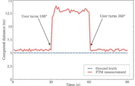
Fig. 1: Distance estimation with FTM. Ground truth at5 m.
point. It promises meter-level accuracy, inferior to some recent works [7], but sufficient for many applications, such as smart home occupancy [6] or shopping mall navigation. More importantly, a standardized and native firmware implementation using clocks with picosecond resolution, can make WiFi FTM a major turning point in the indoor positioning becoming a standard service on our mobile devices. While 802.11mc is not supported by all WiFi devices currently deployed, it has already gained the support of major WiFi manufacturers [11], and it is adopted by the Android operating system [12]. The recent Google Pixel 2 and 3 phones, for example, are 802.11mc-compliant.
While in theory WiFi FTM is looking like a breakthrough moment, the reality is more mixed. Consider the simple case of a user standing5 m from an access point with FTM support and collecting readings on a device with a WiFi FTM card. Fig. 1 shows that, for the first 30 s while the user is facing the access point and there is a clear line of sight (LOS), FTM estimates almost perfectly the distance between the user and the access point. It suffices, however, for the user to turn 180◦,
thus obstructing the line of sight between the client and the access point, for the FTM’s accuracy to collapse. This can be explained by the presence of multipath indoors. Starting at time 30 s, the signal following the line of sight is attenuated by the presence of the human body, leading FTM to estimate distance based on a (stronger) reflected signal. This weakness of WiFi FTM in non-line-sight scenarios (NLOS) was recently showed in [13], however, no solution was proposed. MUSIC (MUltiple SIgnal Classification) [14], may seem like the natural approach to resolving the multiple paths and compute the time-of-flight of the direct path. Unfortunately, multiple studies [15], [16]
have shown that it performs poorly on WiFi hardware. In this work we present FUSIC, an approach fusing FTM and MUSIC with the goal of extending FTM’s LOS accuracy to NLOS settings. FUSIC requires no changes to the standard – it simply takes as input the FTM ranging estimates, the WiFi channel state information (CSI) readings, and corrects the error when it detects that one has occurred. Thereby, FUSIC can be implemented as a stand-alone, user-level application on mobile devices and without requiring any modification to the access points.
To realize its goal, FUSIC faces several challenges. First, while the FTM performance in NLOS shown in Fig. 1 was thoroughly evaluated in [13], two key underlying questions were left open: 1) How do the multiple instances of the transmitted signal and their relative strengths impact the FTM accuracy, and 2) Do obstacles play an additional role in the observed inaccuracy. The radio-wave signal slows down when it crosses obstacles by a factor that depends on their relative permittivity. FTM transforms the ToF to distance by using the speed of light, leading to potential errors. The impact of such errors, however, on FTM has not been studied yet.
Second, FUSIC needs to detect when the value returned by FTM is inaccurate, even though this value and CSI are its only input. A straightforward approach might be to apply MUSIC on the CSI to obtain the power-delay profile and conclude there is an error when the direct signal is not the strongest. However, our measurements show that FTM can be accurate even when the direct signal is not the strongest; applying correction on an accurate result can make it erroneous. Finally, once FUSIC detects that FTM has returned an inaccurate result it needs to correct it while having as input only this value and MUSIC’s power-delay profile – both erroneous.
In short, we address these challenges by first conducting a measurement-based analysis on off-the-shelf hardware designed to shed light on the factors leading to the poor performance of WiFi FTM in NLOS. Coupling FTM output with MUSIC’s power-delay profile of the received signals, we develop a fine-grained understanding of the relation between multipath and FTM. We leverage this understanding for designing FUSIC’s two integral parts: a mechanism for identifying when FTM returns erroneous results, and an error correction mechanism fusing data from FTM and MUSIC.
Our main contributions may be summarized as follows:
• In Section III, we conduct a measurement analysis of WiFi
FTM and MUSIC using off-the-shelf hardware. We assess the magnitude of the FTM weaknesses in NLOS and study the underlying reasons at the signal level. Furthermore, we assess MUSIC’s ability to help improve the accuracy of FTM.
• In Section IV, we use the lessons learned in our measurement
analysis to design FUSIC, an algorithm that takes as input the FTM distance estimates and CSI and 1) is able to detect whether the FTM ranging result is inaccurate and 2) correct the FTM ranging result when necessary.
• In Section V, we use a testbed comprising off-the-shelf
hardware to conduct an extensive evaluation of FUSIC in
4 different physical settings, including a controlled setting, a university restaurant, a warehouse and a student lounge. Our experiments show that a) FUSIC extends FTM’s LOS ranging accuracy to NLOS settings – hence, achieving its stated goal; b) it significantly improves FTM’s capability to offer room-level indoor positioning.
II. BACKGROUND
This section presents the necessary background to understand our contribution.
A. Channel State Information (CSI)
In wireless systems, the signal that reaches a receiver is generally altered (eg. attenuated and reflected) by the channel in which it travels before reaching the receiver. If we denote by x the signal sent by the transmitter, the signal y that reaches the receiver is given by the equation
y = H ∗ x + n (1) where the matrix H represents the complex attenuation and phase shifts undergone by the signal while going through the channel, and n the ambient noise, often assumed to be white Gaussian with zero mean. H is called Channel State Information (CSI) and represents the properties of the channel between the sender and the receiver. Many research works [6], [7], [15]–[21] have used CSI in their solutions as processing them can give useful information about the signal propagation, including Time of Flight (ToF), Angle of Arrival (AoA) and Power Delay Profile (PDP).
B. MUSIC in the frequency domain: ToF estimation of multiple propagation paths
In the interest of brevity, we provide an intuitive summary of MUSIC (MUltiple SIgnal Classification) [14], necessary to understand our work. For an in-depth description we refer the interested reader to [14], [15], [18]. MUSIC algorithm distinguishes signals based on predictable variations of phase when it comes from a specific location. It relies on the measurements obtained from each subcarrier of an OFDM system (as is the case of WiFi, for example). This is feasible because for a given ToF, a difference in terms of signal frequency produces a difference in terms of phase at the receiving system. In fact, two signals that reach an antenna after having travelled during a ToFτ will reach that antenna with a predictable phase difference of −2π × (fj− fi) × τ ,
with fj and fi being the frequencies of those signals. This
means that, with the knowledge of signal measurements on different subcarriers of an OFDM WiFi band, it is possible to resolve the ToFs over different propagation paths. MUSIC uses this property to build a model that is able to resolve the ToFs of different propagation paths. MUSIC algorithm takes as input the CSI corresponding to the communication and returns a spectrum indicating the signal power perceived at each instant by the receiver, a kind of PDP. From such a spectrum, propagation paths can be identified by taking the peaks of the spectrum. This gives an estimate of their ToFs and Power.
C. Fine Timing Measurement (FTM)
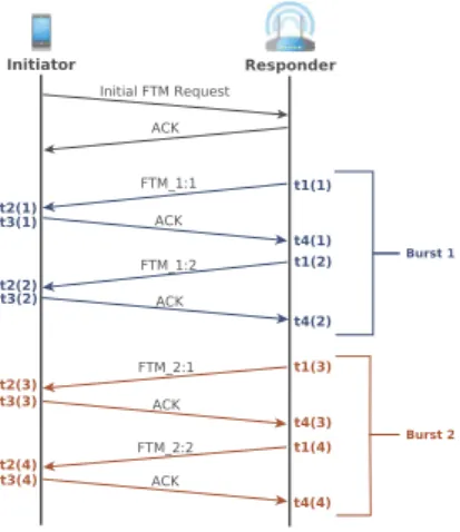
Fig. 2: FTM protocol overview.
The Fine Timing Measurement (FTM) protocol has been standardized in IEEE 802.11-2016 (included as part of the 802.11mc amendment) [9]. It enables a WiFi station to compute the distance to an access point in range without having to associate to the particular access point. The protocol works by estimating the ToF between the two WiFi devices, that is, the time it takes for a signal transmitted by one device to reach the other.
As summarized in Fig. 2, the process starts with a WiFi station (called initiator) which scans for access points sup-porting FTM. If an FTM-capable access point is detected, the initiator sends to the latter an FTM request frame. Upon the reception that request, the access point can choose to ignore it, or to become a responder. In the latter case, the two stations start a series of (FTM, ACK) packet exchanges, called burst, allowing the initiator to estimate the round trip time (RTT) with the responder. An FTM burst consists of the responder sending multiple FTM packets, which are all acknowledged by the initiator. Both stations capture the timestamps at which the burst packets are sent and received. The RTT is calculated as follows:
RT T = (t4− t1) − (t3− t2)
wheret1 andt2represent the time at which the FTM packet is
sent by the responder and received by the initiator, respectively, andt3,t4, the time the ACK is sent by the initiator and received
by the responder, respectively. Finally, the distance between the two devices is derived from the ToF (which is half the RTT) by multiplying the latter by the speed of light. Notice that, an FTM session may also consist of several bursts. In this case, the number of bursts is negotiated at the beginning of the process. The RTT over an FTM session with N bursts is the average of each burst RTT.
While the approach underlying FTM is not novel, its standardization by the IEEE and, therefore, its native imple-mentation in the firmware of WiFi network interface controllers (NICs) using timestamps with picosecond resolution [9] have
AP (Responder) Target (Initiator) Obstacle Reflector Time of arrival Amplitude
Fig. 3: The multipath problem.
the potential to make a significant difference in practice. In the next section, we use some of the first NICs with native FTM support placed on the market to evaluate its accuracy.
III. FTM,ITSMULTIPATHPROBLEM ANDMUSIC According to the WiFi Alliance, FTM provides ranging with meter-level accuracy [11]. However, a recent study [13] showed that while this claim is generally true for clear line-of-sight settings, it is not the case in non-line-of-line-of-sight (NLOS) scenarios. At the high level, the problem is due to the presence of obstacles and multipath, inherent to indoor settings. As illustrated in Fig. 3, the reflected signal may be stronger than the line-of-sight signal, leading the initiator to consider the length of the reflected path as the distance to the responder.
However simple and clear this explanation may seem, the reality, especially on real hardware, as we show in the following, is more nuanced. Questions left unanswered in [13], include: 1) How do the multiple instances of the transmitted signal and their relative strengths impact FTM accuracy, and 2) Do obstacles play an additional role in the observed inaccuracy. The radio-wave signal slows down when it crosses obstacles by a factor that depends on their relative permittivity. FTM transforms the ToF to distance by using the speed of light, leading to potential errors. The impact of such errors, however, on FTM in typical scenarios has not been studied yet.
Finally, considering that FTM limitations involve multipath, MUSIC may seem like the natural approach to resolving the multiple paths and compute the ToF of the direct path. Unfortunately, multiple studies [6], [15], [16] have shown that it performs poorly on WiFi hardware. What is unknown, however, is to what extent, if any, MUSIC can help improve the accuracy of FTM.
To answer these questions, we carry out a measurement-based analysis using off-the-shelf hardware (see § V-B for a full description of our testbed). The lessons learned will help drive the design of our solution, FUSIC, presented in § IV.
A. Problem assessment
Clear line of sight: To establish a baseline, we start our analysis with the simple case in which there is a clear line of sight between the initiator and the responder. We place the two stations in a long corridor and measure their distance with FTM while varying the actual distance between them from1 to 60 m. Each experiment is repeated 5 times, and we take as output the average and standard deviation of all the
Fig. 4: Accuracy of FTM in clear line-of-sight scenarios.
(a) Controlled multipath experimental setup
(b) Distance estimation with FTM as well as the actual reflected path length
Fig. 5: FTM accuracy in different settings: clear or obstructed line-of-sight.
experiments. As expected, Fig. 4 shows that FTM performs very well in this situation, with an average estimation error of 0.76 m and 1.56 m 90-percentile.
Obstructed line of sight in presence of multipath: To evaluate FTM accuracy in NLOS scenarios, we set up the following experiment, illustrated in Fig. 5(a). We place the two stations in a setting where there is a reflector (a wall). The distance between the two stations, L, is varied from 2 m to 10 m in steps of 2 m. The distance to the reflector, D, varies between two values: 6 m, 8 m. For every value of L and D, we perform experiments using two different configurations: one with clear line of sight and one with a person standing between the two stations.
Fig. 5(b) shows the obtained results. The straightforward observation is that FTM is inaccurate when the line of sight is obstructed – the error is up to3.03 m for D = 6 m and 7.62 m forD = 8 m.
A more subtle observation is that, in NLOS settings, FTM
(a) Experimental setup in open-space environ-ment
(b) FTM performance for different numbers of obstacles (per-sons) as well as the observed RSSI.
Fig. 6: Experiments in a multipath-free environment (football stadium). Adding people in the line of sight has negligible effect on FTM distance estimation even if it impacts the received signal strength (RSSI).
does not return the length of the path followed by the reflected signal. In Fig. 5(b), we have added the geometrical length (theoretical value) of the reflected path, which we can calculate because we have a semi-controlled setting with a single reflector. The data shows that FTM output is between the value of the direct path and the theoretical value of the reflected path. In § III-B, we explore the root causes of this observation and use the findings to drive our solution.
Obstructed line of sight with no multipath: We conduct a similar experiment in an outdoor open space (absence of multipath) in order to verify the source of FTM errors in NLOS settings: multipath effect or relative permittivity of the obstacle in the line of sight. To this end, we perform FTM measurements at different distances, while varying the number p of persons between the two devices, p ∈ 0, 1, 2, 3. Fig. 6(a) shows the experimental setup with one person as obstacle. In these experiments, we also record the received signal strength indication (RSSI) to observe how the signal strength varies with the number of persons as obstacles. As we can see in Fig. 6(b), the insertion of persons as obstacles on the LOS path has negligible effect on distance estimation when there is no multipath. This clearly shows that the effect of relative permittivity is negligible and that our observations when there is a reflector are mostly due to the multipath propagation.
(a) Strong LOS: almost no error
(b) Comparable strengths: low error
(c) Weak LOS: high er-ror
Fig. 7: Normalized MUSIC spectrums in three different situations
Fig. 8: Error vs relative strength of LOS
B. The origin of the issue in the multipath settings
To gain a better understanding as to the root causes of the FTM’s poor accurracy in the presence of multipath, we place ourselves in the multipath experimental environment of Fig. 5(a), with L = 5 m and D = 8 m. We run a series of experiments using up to 8 volunteers to act as obstacles. New to this round of experiments, we add near the responder a computer equipped with an Intel 5300 WiFi NIC and run the Linux CSI tool [22] to collect CSI during the experiment.
We start our analysis by aiming at understanding FTM results at the signal level. We place the two FTM devices in three different settings: short distance (L = 2m) and clear line of sight; medium distance (L = 6m) and obstructed line of sight (one person), and long distance (L = 10m) and highly obstructed line of sight (2 persons). In addition to FTM data, we collect CSI and use MUSIC to analyze the PDP. The data for the first setting, Fig. 7(a), are as expected: when the LOS is clear, the direct path is dominant and the error is negligible. On the other hand, the data of Fig. 7(b) and Fig. 7(c) provide a more nuanced understanding of what happens in NLOS. The accuracy of FTM is not a simple function of whether there is a clear LOS or not. Instead, it depends on the strength of the direct signal relative to the reflected signal. When the direct signal is similar in strength to the reflected signal, Fig. 7(b), FTM is still reasonably accurate. However, when the reflected signal is clearly stronger, FTM becomes inaccurate, Fig. 7(c).
To further validate these findings, we carry out a new series of experiments in which we change the level of obstruction by having up to 8 volunteers standing in the LOS between the two FTM devices, withL = 5 m and D = 8 m. Fig. 8 shows the FTM error as function of what we define as signal strength ratio. It captures the strength of the direct signal relative to the combined strength of all signals reaching the receiver. Formally,
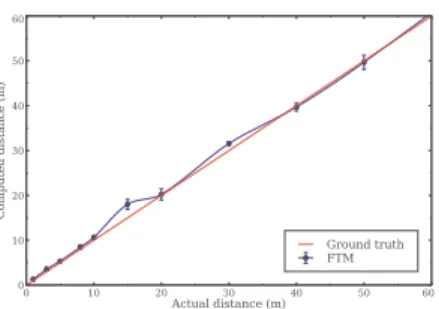
Fig. 9: Distance estimation based on CSI. Ground truth at5m.
the signal strength ratio is defined as: P (τ1)
PK
k=1P (τk)
where K is the number of resolved paths, τk and P (τk) are
the ToF and strength of pathk (k = 1 corresponds to the direct path), respectively.
As we can see in Fig. 8, the value of the FTM errors depend on the strength of the direct path relative to the NLOS paths. We leverage this finding in § IV as part of our solution for correcting FTM.
C. MUSIC and the inaccuracy problem
We evaluate the capability of MUSIC to accurately estimate the ToF using CSI from off-the-shelf WiFi network interface controllers. Towards this, we place a WiFi station and access point (AP) at a distance of5 m from each other. The station transmits a series of 100 packets while the AP records the CSI for each packet. The experiment is performed indoors with a reflector 8 m from the line of sight between the station and access point. In this setting, we expect to get two paths with lengths 5 m and 16.8 m, respectively. We apply MUSIC on each CSI entry and consider the delays of the first and second peak as the estimated ToF for the direct and reflected path, respectively. We convert the ToF to distance by multiplication with the speed of light. Fig. 9 shows that the distance estimation error is significant, varying between 32 m and 61.8 m. This corresponds to about 12-time the actual distance, on average. These observations are consistent with findings in [6], [16]. What is more, the values calculated by MUSIC are highly variable from one packet to another(6.9 m standard deviation), rendering ineffective any static calibration (which consists in averaging the error and removing it from the following ToF estimates).
Nevertheless, Fig. 9 points to a very interesting observation. While the direct and reflected paths estimated distances are highly erroneous,the difference in the estimates of the two path lengths is the same across all 100 packets and corresponds to the actual difference of paths lengths. In this particular experiment, we observe an almost constant offset of 12.3 m. This observation has also been pointed by other works [6], [7], [15], [16]. We leverage it in the design of FUSIC, our solution presented in the next section.
IV. FUSIC
In this section, we present FUSIC, an algorithm fusing WiFi FTM and MUSIC for delivering accurate ranging even in the presence of multipath. FUSIC takes as input the potentially erroneous, FTM output, and the CSI matrix and returns the distance between two WiFi FTM devices. FUSIC requires no changes to the standard, no changes to the access points and can be implemented as an application on the user’s device.
FUSIC faces two key challenges. First, it needs to identify when FTM is mislead into calculating the distance based on the reflected signal. Second, when FTM is mislead, it faces the challenge of correcting the error and returning the length of the direct path.
The key intuition driving the design of FUSIC is that FTM is mislead when the LOS path is not the most dominant path (§ III-B, Fig. 7). MUSIC, on the other hand, provides the power-delay profile of all paths, allowing to identify when the direct path is not the dominant one. A fusion of the two can pave the way for an approach identifying when FTM is incorrect and correcting its output as necessary. However, turning this intuition into a practical solution addressing our two key challenges is not trivial. First, as our data shows (Fig. 7(b)), FTM can return accurate distance estimates even if the LOS path is not the most dominant path. In this case, trying to correct can lead to worse results. Second, even knowing when FTM is erroneous, is it not clear how fusing it with results from MUSIC, shown to be highly inaccurate, will somehow lead to accurate results. Algorithm 1 summarizes how FUSIC addresses all these challenges. Next, we describe the key contributions of the algorithm.
A. Detecting when FTM needs correction
As our measurement data in § III-B, Fig. 7 showed, the question of whether FTM is correct cannot be reduced to simply knowing whether the direct path is the most dominant or not. There are cases in which the direct path is not the most dominant and yet FTM returns accurate results. Therefore, deciding when to correct FTM is more challenging that it may seem at first look.
To address this challenge, FUSIC introduces a new parameter, R, which quantifies the contribution of the direct path to the overall MUSIC spectrum (line 2, Algorithm 1).R is defined as:
R = PKP (τ1)
k=1P (τk)
and is similar to lfactor metric used in CUPID [17].
When the value of R is above a threshold, Rthreshold,
FUSIC does not perform any correction (line 4, Algorithm 1). Otherwise, it will trigger the correction algorithm introduced in § IV-B. Selecting the right value for Rthreshold requires
addressing an interesting tradeoff: If the threshold is too low, FUSIC may alter accurate FTM measurements, leading to unnecessary errors. On the other hand, if it is too high, FUSIC may fail to correct erroneous FTM measurements. In our prototype, we have selected Rthreshold to be conservative on
the side of applying the error correction algorithm less often. Extensive evaluation in § V, usingRthreshold= 0.5, show that
our approach leads to significant improvements. Algorithm 1: FUSIC
Input:csi matrix: The measured CSI matrix df tm: The distance measured by FTM
Output: df usic: The corrected distance estimation 1 Identify the dominants paths using MUSIC algorithm
{(tk, Pk)}1≤k≤K= music spectrum(csi matrix),
withtk andPk being respectively resolved ToF and
Power of pathk;
2 Compute the relative strength of direct path with
respect to others asR = PP(τ1) K
k=1P(τk) ;
3 ifR ≥ Rthreshold then
4 Conserve the FTM distance estimatedf usic= df tm; 5 else
6 Compute the mean excess delay as
¯ τ = P K k=1PP(τk)(τk−τ1) K k=1P(τk) ;
7 Compute the corrected distance estimate as
df usic= df tm− ¯τ × c, with c ≈ 3 × 10⁸m s−1
being the speed of light;
8 end
9 returndf usic;
B. Correcting the FTM output
To introduce our error correction algorithm, we first consider a special case and use it as springboard for introducing our general-purpose algorithm.
Error correction for a special case: Let us start by considering the special case in which there are only two propagation paths between an initiator and a responder: a LOS path which is strongly obstructed and a reflected path. This case corresponds to something we observed in Fig. 7(c). In this instance, FTM will output the length of the reflected path. The FTM error can be expressed as the difference between its output and the length of the LOS path. The idea behind FUSIC is to leverage MUSIC to estimate the FTM error and thereby correct its output. The challenge is how can MUSIC, highly erroneous on WiFi hardware, help estimate the error of FTM, which actually works better.
To address this challenge, we leverage a key observation we made in § III-C: Despite its inaccuracy, the difference in estimated ToFs (thus distances) generated by MUSIC for any two paths is actually accurate. Hence, FUSIC can use the inaccurate ToF estimates of the propagation paths resolved by MUSIC to compute the FTM measurement error. ¯dǫ =
(τref lected− τdirect) × c, with τdirect andτref lected being the
ToF estimates of the direct and reflected paths, respectively.c ≈ 3 × 10⁸m s−1 represents the speed of light. The direct path is
taken from the MUSIC spectrum as the one with the minimum estimated ToF. With the knowledge of ¯dǫ, FUSIC computes an
accurate value of the direct path ToF by subtracting this value from the FTM distance measurement:df usic= df tm− dǫ.
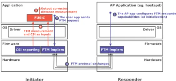
Fig. 10: An example of a product-level implementation of FUSIC, implemented in the initiator’s wireless driver.
General-purpose algorithm: In the general case, we may have several propagation paths between an initiator and a responder and we cannot make any assumptions as to the relative power levels of the different signals reaching the receiver. Under such circumstances, as we observed in § III-A, Fig. 5(b), the FTM measurements do not necessarily reflect the length of a particular propagation path. Instead, FTM returns a value between the length of the direct path and that of the reflected path. What is more, the FTM errors increase as the LOS signal gets weaker relative to the NLOS signals (Fig. 8).
We model this phenomenon by considering the FTM output as not being the length of an actual reflected path but of a virtual
path whose length is influenced by the lengths and relative strengths of the most dominant propagation paths. Therefore, FUSIC takes into account all the path length differences relative to the direct path computed by MUSIC and assigns them weights proportionally to their power levels. The estimated FTM measurement error,τ , in terms of ToF (= ¯¯ dǫ/c), is then
computed as the weighed average of ToF differences to the direct path’s ToF (line 6, Algorithm 1):
¯ τ = PK k=1P (τk)(τk− τ1) PK k=1P (τk)
a quantity also referred to as the mean excess delay [23], [24]. FUSIC finally removes the effect of the error (line 7, Algorithm 1) and outputs the corrected distance estimate as: df usic= df tm− ¯τ × c.
V. PERFORMANCE EVALUATION
After a quick presentation of a prototype of FUSIC, this section focuses on the evaluation results of FUSIC. We first evaluate its accuracy, followed with its utilization for indoor localization. The latter is the most common use case for WiFi-based ranging solutions. For this use case, we implement a classical non-linear trilateration algorithm [25]. For all experiments we compare FUSIC with vanilla FTM.
A. FUSIC implementation
One of the strengths of FUSIC is that it requires no modification to the standard. It just takes the output of FTM and processes it with the knowledge of CSI. This process should be done on the initiator’s side because only the initiator knows the output of the FTM protocol. There are many ways FUSIC can be implemented: either as a user-space application,
or beforehand in the wireless driver or firmware (directly by Original Equipment Manufacturers) in such a way to be totally transparent to upper-layer applications. Fig. 10 shows an example of such an implementation which fits well with indoor localization purposes. There, FUSIC, implemented at the application layer, intercepts FTM output and performs the eventual correction before actually using the results. Our prototype follows this implementation choice.
B. Experimental Setup
Hardware. Our experimental setup is similar to [13]’s open platform. We use one Dell Latitude 5480 laptop equipped with an Intel 8260 WiFi NIC chipset as the initiator and three Asus Wireless-AC1300 RT-AC58U routers (access points) with the Qualcomm IPQ4018 chipset as the responders. Both Intel 8260 and Qualcomm IPQ4018 chipsets are FTM-capable and have the WiFi Location certification from the WiFi Alliance [11]. All stations use 80 MHz bandwidth at 5 GHz as in [13]. To simplify the experimentation process (which consists of several measurements), we choose to run FUSIC on the router side instead of the client as it should be in practice (see Fig. 10). Notice that this setup does not impacts the results because CSI and FTM data are the same in both sides. Knowing that our testbed routers do not allow CSI reporting, we emulate the ideal router by attaching to each Asus Wireless-AC1300 RT-AC58U router a device which allows CSI reporting (see Fig. 11(a)). We use Dell Vostro 15 3000 series computers, equipped with Intel 5300 WiFi NICs and running the well-known Linux CSI tool [22] for this purpose. Notice that such a combination of devices to enable CSI reporting in research works is not new [17]. We also believe CSI reporting is going to become a common feature in new WiFi NICs drivers, as many new applications rely on them. Intel’s iwlwifi wireless driver, for example, has already integrated CSI reporting as a feature to come in its next releases [26].
Software. The initiator runs Ubuntu 16.04 operating system with Linux kernel 4.14.0 and a modified version [13] of the backported LinuxCore30 release of Intel’s iwlwifi wireless driver. Concerning the routers, they run OpenWrt Snapshot r1834-0f04829 with Linux kernel 4.9.86 which includes FTM-capable Qualcomm Atheros ath10k driver and firmware. For FTM request initiation, we use a modified version of iw command line tool in which FTM protocol capabilities has been added1. All the measurements are repeated 30 times and
averaged. Finally, to evaluate omnidirectional communications (which are more common), we make sure that beamforming is disabled during all the experiments by setting ath10k’s parameters accordingly on the AP side.
Spatial contexts. We evaluate FUSIC in four spatial contexts. The first context, which is a synthetic one, is the controlled multipath setup presented in Section § III and summarized in Fig. 5(a). The three other contexts are indoor buildings, representing real human living environments: a university restaurant (23 m × 13.5 m, Fig 11(b)), a technical warehouse
(a) The receiving sys-tem
(b) Setup in the uni-versity restaurant
(c) Setup in the ware-house
(d) Setup in the lounge
(e) University restau-rant map
(f) Warehouse map (g) Lounge map
Fig. 11: Experimental setup
Fig. 12: FUSIC vs FTM in time-variant experiment.
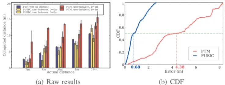
(a) Raw results (b) CDF
Fig. 13: FUSIC vs FTM at different distances, with obstructed LOS.
(13 m × 12.5 m, Fig. 11(c)), and a lounge (15 m × 13.5 m, Fig. 11(d)). Fig. 11(e), 11(f), and 11(g) respectively show the maps of the different rooms. The three responders have fixed positions in the spatial contexts (represented by blue circles on the maps). Concerning the initiator, we experiment several positions in each spatial context (represented by red circles on the maps), for a total of 122 tested target locations. In addition to the user holding the target device, these indoor contexts include two other people walking, standing and sitting in a random way. The ground truth is obtained using a30 m long measuring tape.
C. Accuracy in the synthetic spatial context
This experiment is realized in the first spatial context (Fig. 5(a)). We first place the initiator and responder at a distance of L = 5 m from each other and D = 8 m from the wall. We conduct the same time-variant experiment described in Section § III: the user make a 180° turn at time t = 30 s and a 360° turn at t = 60 s. Fig. 12 presents the results. We can see that FUSIC is able to accurately estimate the distance during all the
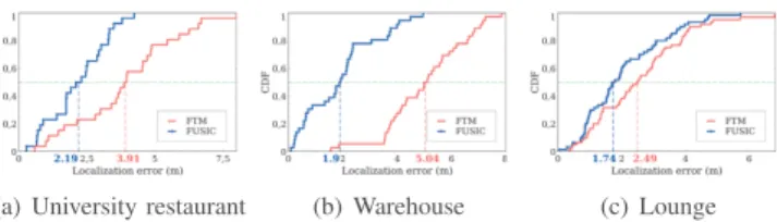
(a) University restaurant (b) Warehouse (c) Lounge
Fig. 14: FUSIC and FTM accuracy in three real indoor rooms.
experiment. This is not the case for FTM when the user stands between the initiator and the responder, as already stated in Section III.
Next, we vary the distanceL between the equipments and the distanceD from the wall, as in Section § III. Fig. 13(a) presents the estimated distances while Fig. 13(b) presents the Cumulative Distribution Function (CDF) of the estimation error for all the evaluated positions. FUSIC achieves a median and 90-percentile of 0.68 m and 2.12 m respectively while FTM ones are4.38 m and 7.8 m respectively. These results clearly show that FUSIC is able to bring back the estimated distances to almost the clear LOS FTM measurement and validate the effectiveness of the approach introduced by FUSIC.
D. Accuracy in real indoor environments
Here, we perform experiments in the three indoor spatial contexts (Figs. 11(b), 11(d) and 11(c)). For each of the spatial contexts, and for each of the target locations (red dots on the maps), we perform FTM measurements and collect CSI on the routers sides. We later on apply FUSIC on these data and compute the error with respect to the ground truth. Fig. 14 presents the CDFs of the distance estimation errors for each of the three rooms. We can see that FUSIC beats FTM in accuracy in all the three spatial contexts. This is normal because FTM is influenced by the complexity of propagation environment while FUSIC takes it into account in order to output accurate distance estimations. We can also notice that the minimal difference between FUSIC and FTM is achieved in the lounge. This is explained by the fact that it is the spatial context with the less obstacles, thus the less challenging multipath environment. Taking all the data into account, FUSIC achieves a median and 90-percentile of1.27 m and 3.41 m respectively, outperforming FTM, whose overall performance is2.32 m for the median and 5.28 m for the 90-percentile.
(a) University restaurant (b) Warehouse (c) Lounge
Fig. 15: Indoor localization using FUSIC and FTM.
E. Use case: Indoor localization
Here we evaluate FUSIC’s ability to yield accurate local-ization. For this evaluation, we compute target’s locations using the data obtained during the experiments presented in the previous section. This is done using the classical Least Square Optimization approach [25] which consists in looking for the location that minimizes the sum of squared errors to the observed distances to the routers. We then compare the outputted locations to the known ground truth. Fig. 15 presents the CDFs of the location estimation errors for each spatial context. As we can see, localization based on FUSIC is more accurate than the one with vanilla FTM. This is not surprising since FUSIC proved itself being more accurate in distance estimation than FTM, especially in challenging multipath environments (See Section V-D). In the technical warehouse for example, which is the most challenging multipath setting, the difference is impressive:1.9 m of median localization error with FUSIC versus5.04 m with FTM. Overall, taking all the locations estimates into account, FUSIC achieves a median and 90-percentile of1.94 m and 3.77 m respectively. Concerning FTM, it achieves a median and 90-percentile of 3.64 m and 5.79 m respectively.
VI. RELATED WORK
Ranging using WiFi is a well studied problem. We present only a set of representative works and refer the interested readers to [27] and [28] for more complete surveys.
The existing approaches for WiFi based ranging can be classified in two main categories: Received Signal Strength Indicator (RSSI) based and Time of Flight (ToF) based. We also dedicate a special paragraph to Fine Timing Measurement (FTM).
RSSI-based approaches. Many research works have used RSSI, which characterizes the attenuation of a radio signal during its propagation. Those works generally use the well-known path-loss propagation model [1], [29]. Some other works combine this model with classical filtering techniques like Kalman filter [30] or with more sophisticated algorithms like Gaussian Process Latent Variable Models [31], [32]. Similar to pure RSSI-based techniques, works like [33] build CSI-based path-loss like relations in order to improve the accuracy. However, as the received signal strength depends on many environmental factors including the existence or not of obstacles and their natures, the density of multipath reflections and even the ambient temperature and humidity, these approaches include limitations due to the difficulty to build propagation models
that perfectly fit the reality of different indoor environments. Compared to those solutions, FUSIC relies on FTM which is a ToF-based solution, and thus does not suffer from these problems.
ToF-based approaches. Multiple works in this category use timestamp-based techniques on top 802.11 MAC protocol, either with the packets echoing technique [34], [35] or with custom-made synchronization-free protocol [36]. [37] and [10] also proposed methods for filtering out the measurement noises due to multipath propagation. On the other hand, some recent works like [16] and [38] focused on removing the errors inherent to CSI obtained from commodity WiFi NICs in order to perform accurate ranging via super-resolution techniques like MUSIC algorithm. [6], [18], [19] combined the measurements on multiple WiFi bands to form a virtual wider bandwidth, aiming at achieving finer resolution. Although some of those systems achieve remarkable accuracy, the lack of standardization makes them difficult to adopt in real world usage as there is no guarantee of interoperability between them. FUSIC, on the other hand, leverages the standardization of FTM protocol and is designed to be deployed in such a way to be transparent and stay compliant with the standard.
Fine Timing Measurement. As a new algorithm in 802.11 standard (late 2016), FTM has so far gained the attention of only few research works. [13] studied FTM accuracy in different real world scenarios including indoors and outdoors, and proposed a measurement framework for evaluating such time-based ranging systems. Some other works use FTM measurements as inputs to their system either to improve their sensor fusion based Pedestrian Dead Reckoning [39] or to perform collaborative positioning in a wireless network [40].
While these works either only discuss the accuracy of FTM algorithm or use it as is, the challenge addressed by the present work is to make FTM accurate in Non-Line-Of-Sight conditions as it does in Line-Of-Sight ones. FUSIC, has been shown to give a solution to that challenge, making FTM work well even in highly challenging indoor environments.
VII. CONCLUSION
We presented FUSIC, an approach fusing FTM and MUSIC with the goal of extending WiFi FTM line-of-sight (LOS) accuracy to non-line-of-sight (NLOS) settings. FUSIC is the first approach which tackles this issue. It requires no changes to the standard and can be implemented as a stand-alone, user-level application on mobile devices. We implemented FUSIC on a testbed consisting of off-the-shelf hardware and through experiments in 4 different physical locations demonstrated that it can provide ranging in NLOS of the same accuracy as FTM’s in LOS – hence, achieving its goal. Furthermore, our experiments demonstrate that FUSIC significantly improves FTM’s capability to offer room-level indoor positioning. We believe FUSIC can also be an effective solution for other ranging-based applications and services, including device tracking and indoor mapping, which are among our future works.
ACKNOWLEDGMENT
This work was supported in part by the Agence Nationale de la Recherche under the ANR JCJC CiTADEL grant.
REFERENCES
[1] P. Bahl and V. N. Padmanabhan, “Radar: an in-building rf-based user location and tracking system,” in Proceedings IEEE INFOCOM 2000.
Conference on Computer Communications. Nineteenth Annual Joint Conference of the IEEE Computer and Communications Societies (Cat. No.00CH37064), 2000, pp. 775–784 vol.2.
[2] Y. Ma, N. Selby, and F. Adib, “Minding the billions: Ultra-wideband localization for deployed rfid tags,” in ACM MobiCom, 2017, pp. 248– 260.
[3] S. Shen, M. Gowda, and R. Roy Choudhury, “Closing the gaps in inertial motion tracking,” in ACM MobiCom, 2018, pp. 429–444.
[4] S.-M. Moosavi-Dezfooli, Y.-A. Pignolet, and D. Dzung, “Simultaneous acoustic localization of multiple smartphones with euclidean distance matrices,” in EWSN, 2016, pp. 41–46.
[5] D. Vasisht, G. Zhang, O. Abari, H.-M. Lu, J. Flanz, and D. Katabi, “In-body backscatter communication and localization,” in ACM SIGCOMM, 2018, pp. 132–146.
[6] D. Vasisht, S. Kumar, and D. Katabi, “Decimeter-level localization with a single wifi access point,” in USENIX NSDI, 2016, pp. 165–178. [7] E. Soltanaghaei, A. Kalyanaraman, and K. Whitehouse, “Multipath
triangulation: Decimeter-level wifi localization and orientation with a single unaided receiver,” in ACM MobiSys, 2018, pp. 376–388. [8] (2017, July) Path guide: A new approach to indoor navigation.
[Online]. Available: https://www.microsoft.com/en-us/research/blog/path-guide-new-approach-indoor-navigation/
[9] IEEE, “Ieee draft standard for information technology– telecommunications and information exchange between systems -local and metropolitan area networks–specific requirements part 11: Wireless lan medium access control (mac) and physical layer (phy) specifications,” IEEE P802.11-REVmc/D6.0, June 2016, pp. 1–3774, 2016.
[10] M. Rea, A. Fakhreddine, D. Giustiniano, and V. Lenders, “Filtering noisy 802.11 time-of-flight ranging measurements from commoditized wifi radios,” IEEE/ACM Transactions on Networking, pp. 2514–2527, 2017. [11] W.-F. Alliance®. (2017, Feb.) Wi-fi certified location™ brings wi-fi® indoor positioning capabilities. [Online]. Available: https://www.wi-fi.org/news-events/newsroom/wi-fi-certified-location-brings-wi-fi-indoor-positioning-capabilities
[12] A. developers documentation. (2018) Wi-fi lo-cation: ranging with rtt. [Online]. Available: https://developer.android.com/guide/topics/connectivity/wifi-rtt [13] M. Ibrahim, H. Liu, M. Jawahar, V. Nguyen, M. Gruteser, R. Howard,
B. Yu, and F. Bai, “Verification: Accuracy evaluation of wifi fine time measurements on an open platform,” in ACM MobiCom, 2018, pp. 417– 427.
[14] R. Schmidt, “Multiple emitter location and signal parameter estimation,”
IEEE Transactions on Antennas and Propagation, pp. 276–280, 1986. [15] M. Kotaru, K. Joshi, D. Bharadia, and S. Katti, “Spotfi: Decimeter level
localization using wifi,” in ACM SIGCOMM, 2015, pp. 269–282. [16] W. Gong and J. Liu, “Sifi: Pushing the limit of time-based wifi localization
using a single commodity access point,” ACM UbiComp, pp. 10:1–10:21, 2018.
[17] S. Sen, J. Lee, K.-H. Kim, and P. Congdon, “Avoiding multipath to revive inbuilding wifi localization,” in ACM MobiSys, 2013, pp. 249–262. [18] J. Xiong, K. Sundaresan, and K. Jamieson, “Tonetrack: Leveraging
frequency-agile radios for time-based indoor wireless localization,” in
ACM MobiCom, 2015, pp. 537–549.
[19] Y. Xie, Z. Li, and M. Li, “Precise power delay profiling with commodity wifi,” in ACM MobiCom, 2015, p. 53–64.
[20] A. T. Mariakakis, S. Sen, J. Lee, and K.-H. Kim, “Sail: Single access point-based indoor localization,” in ACM MobiSys, 2014, pp. 315–328. [21] Z. Tian, Z. Li, M. Zhou, Y. Jin, and Z. Wu, “PILA: sub-meter localization
using CSI from commodity wi-fi devices,” Sensors, 2016.
[22] D. Halperin, W. Hu, A. Sheth, and D. Wetherall, “Tool release: Gathering 802.11n traces with channel state information,” ACM SIGCOMM Comput.
Commun. Rev., pp. 53–53, 2011.
[23] R. Bharadwaj and S. K. Koul, “Study and analysis of channel character-istics of ultra-wideband communication links using wearable antennas,” in 2017 IEEE Asia Pacific Microwave Conference (APMC), 2017, pp. 45–48.
[24] S. Forcellini and L. C. Trintinalia, “Location estimation using relationship between delay spread and mean excess delay,” in Proceedings. 2005
IEEE Networking, Sensing and Control, 2005., 2005, pp. 638–643. [25] F. Izquierdo, M. Ciurana, F. Barcelo, J. Paradells, and E. Zola,
“Perfor-mance evaluation of a toa-based trilateration method to locate terminals in wlan,” in 2006 1st International Symposium on Wireless Pervasive
Computing, 2006, pp. 1–6.
[26] Intel. (2019, Jan.) iwlwifi: mvm: implement csi reporting. [Online]. Available: https://git.kernel.org/pub/scm/linux/kernel/git/iwlwifi/iwlwifi-fixes.git/commit/?id=5213e8a8a28d2c4c143fec94e57c866a958ed52d [27] F. Zafari, A. Gkelias, and K. K. Leung, “A survey of indoor localization
systems and technologies,” CoRR, 2017.
[28] Z. Yang, Z. Zhou, and Y. Liu, “From rssi to csi: Indoor localization via channel response,” ACM Comput. Surv., pp. 25:1–25:32, 2013. [29] P. Kumar, L. Reddy, and S. Varma, “Distance measurement and error
estimation scheme for rssi based localization in wireless sensor networks,” in WCSN, 2009, pp. 1–4.
[30] I. Guvenc, “Enhancements to rss based indoor tracking systems using kalman filters,” in In GSPx International Signal Processing Conference, 2003.
[31] B. Ferris, D. Fox, and N. Lawrence, “Wifi-slam using gaussian process latent variable models,” in Proceedings of the 20th International Joint
Conference on Artifical Intelligence, 2007, pp. 2480–2485.
[32] A. Goswami, L. E. Ortiz, and S. R. Das, “Wigem: A learning-based approach for indoor localization,” in ACM CoNEXT, 2011, pp. 3:1–3:12. [33] K. Wu, Jiang Xiao, Youwen Yi, Min Gao, and L. M. Ni, “Fila: Fine-grained indoor localization,” in IEEE INFOCOM, 2012, pp. 2210–2218. [34] S. A. Golden and S. S. Bateman, “Sensor measurements for wi-fi location with emphasis on time-of-arrival ranging,” IEEE Transactions on Mobile
Computing, pp. 1185–1198, 2007.
[35] D. Giustiniano and S. Mangold, “Caesar: Carrier sense-based ranging in off-the-shelf 802.11 wireless lan,” in ACM CoNEXT, 2011, pp. 10:1– 10:12.
[36] M. Youssef, A. Youssef, C. Rieger, U. Shankar, and A. Agrawala, “Pinpoint: An asynchronous time-based location determination system,”
in ACM MobiSys, 2006, pp. 165–176.
[37] M. Ciurana, F. Barcelo-Arroyo, and F. Izquierdo, “A ranging system with ieee 802.11 data frames,” in 2007 IEEE Radio and Wireless Symposium, 2007, pp. 133–136.
[38] N. Tadayon, M. T. Rahman, S. Han, S. Valaee, and W. Yu, “Decimeter ranging with channel state information,” IEEE Trans. Wireless
Commu-nications, pp. 3453–3468, 2019.
[39] Y. Yu, R. Chen, L. Chen, G. Guo, F. Ye, and Z. Liu, “A robust dead reckoning algorithm based on wi-fi ftm and multiple sensors,” Remote
Sensing, 2019.
[40] L. Banin, O. Bar-Shalom, N. Dvorecki, and Y. Amizur, “Scalable wi-fi client self-positioning using cooperative ftm-sensors,” IEEE Transactions