Development of a Reusable Practice Device
to Measure the Power, Accuracy, and Placement of a Golf Shot
by
Severiano R. Canales
Submitted to the Department of Mechanical Engineering In Partial Fulfillment of the Requirements of the
Degree of Bachelor of Science
at the
Massachusetts Institute of Technology June 2005 MASSACHUSETTS INSTiTUTE OF TECHNOLOGY
:
.. ~
JUN O 8 2005LIBRARIES
©c 2005 Severiano R. CanalesAll rights reserved
The author hereby grants to MIT permission to reproduce and to
distribute publicly paper and electronic copies of this thesis document in whole or in part.
Signature of Author ... ...
Department of Mechanical Engineering May 6, 2005
Certified by C ertifed bv ... ;.. . ~,·~ ~~~~~ .. . v . - f.
~
~ui [:-
-- rnestoE-E'l
Adjunct Professor Thesis Supervisor
Accepted
by ...
.
... ... ...
Ernest G. Cravalho Chairman, Undergraduate Thesis CommitteeDevelopment of a Reusable Practice Device
to Measure the Power, Accuracy, and Placement of a Golf Shot
by
Severiano R. Canales
Submitted to the Department of Mechanical Engineering On May 6. 2005 in Partial Fulfillment of the Requirements for the Degree of Bachelor of Science in
Mechanical Engineering
ABSTRACT
The purpose of this thesis was to develop a reusable practice device that could help golfers analyze their shots. A Magic Pad, consisting of a translucent. plastic top layer and a statically charged thin layer of cardboard, was modified and placed on the clubface. When the clubface strikes the ball, the top plastic layer attaches itself to the bottom layer creating a noticeable impression. By peeling the top layer, the device could be reset and used again several times. A series of tests was conducted to prove the viability of this device.
The device was effective in analyzing several aspects of a golf shot. The marks made on the dev ice from impact with the ball were clear and dark. This device is most effective in determining the placement of the ball on the clubface, but it is also successful in identifying inaccurate shots. Slices occur when the club head does not hit the ball squarely, and this is translated unto the device. A few characteristic marks signal a slice. The most obvious is a mark with amorphous shape, favoring one side of the ball, instead of a circular indentation. Shear streaks, straight diagonal lines at the angle of impact, are also apparent and allow the golfer to adjust their swing to compensate. The third aspect of the shot that the device could have
measured was the power. A bigger indentation did not necessarily produce the greatest yardage, however. The most impressive indentations were produced by a combination of accuracy and power. In this way. the golfer can clearly identify a quality shot. This fact, coupled with the inexpensive materials, makes the device a viable product.
Thesis Supervisor: Ernesto Blanco
Table of Contents
1.0 Introduction ... 4
1.1 State of Sports Innovation
...
4
1.2 Todlay's Golf Environment. ... 4
1. 3 Overview of Prochct Function ...
4
2.0 Development ... 4
2. 1 0ver,'iew of Golf Swing ...
4
2.2 Development Process ... 5
3.0 Data Gathering ... 8
3.1 The Swing Groover...8
3.2 Testing Equipment ... 8 4.0 Results ... 9 4.
l
Device Interference ... 94.2 Ball Placenment...9
4.3 Accuracy ... 104.4 Power...13
5.0 Product in Use ... 146.0 Conclusions and Recommendations ... 15
7.0 Appendix ... 17
7. Supporting Materials
...
1...
7
7. 2 Indentations on Device Face...18
1.0 INTRODUCTION
1. 1 State of Sports In7lovation
MIT's own magazine, Technology Review, recently ran a story about the development of a new basketball with the air pump attached and hidden inside. This recent case is rare because the sporting goods industry has neglected innovation for some time. The exception, as noted in the article, is the golf industry. The golf industry has always been on the cutting edge of technology. Over the years, development in materials has altered the landscape of golf equipment. Shafts
have changed from steel to graphite. The club heads were once wood, but now they are titanium. 1.2 Today 's Golf Environmenl
As golf equipment has gotten better, the price of playing golf has also risen. However, this has not deterred new golfers from coming to the game in droves. Since the late 1990s, the popularity of golf has skyrocketed. The tremendous success of Tiger Woods has made golf accessible to a newv audience, especially minorities and young people.
With such a surge of new amateurs, the demand for practice equipment is greater than ever. As with the golf clubs and balls, this practice equipment is expensive and complicated. Therefore, the goal of this thesis is to develop and easy to use, cheap alternative to golf practice equipment.
There are several methods of analyzing a golf shot. They range from observing the rotation of a ball tied to a post to computer-aided video equipment that captures the motion of a golfer's swing. An easier and cheaper solution would benefit golfers everywhere.
1. 3 Overview oJ Prodluct Funmction
The device will capture the moment when the club head strikes the ball. The indentation of the ball left on the device will be used to determine the position, power, and angle at which the ball was hit. This information can be a huge help to golfers by helping them understand the result of the shot. To ensure the viability of the product, it must be inexpensive, easy to use, and reusable. The steps to creating the product and its effectiveness are related below.
2.0 DEVELOPM[ENT
2.1 Overview of Golf Swing
The typical golf' swing is displayed in Figure 1. A golf swing consists of three parts: the back swing, the down swing, and the follow through. Figure displays a perfect down swing and follow through. It is important to understand the mechanics of a golf swing before any device is developed. The device will be useless if the golfer does not understand what should happen and compare it to what the device shows.
Figure 1: Phases of a Golf Swing
Before starting the swing, the golfer addresses the ball. The golfer's stance is important because the down swing should end at the same position which it started. For tee shots, the golfer plays
the ball near his; front foot, as shown in Figure 1. His knees are bent, and he takes his position at a comfortable distance behind the ball. The club face is placed behind the ball, and the golfer is now ready to begin the back swing.
During the backswing, the golfer shifts his weight to his back foot and takes the club back smoothly, not allowing his front elbow to bend until the last possible instant. At the end of the back swing. the club should be parallel with the ground and pointing towards the target, as seen in Figure 1. The down swing begins as the golfer shifts his weight back, turns his hips and lets the club fall to his side. As the club falls, the golfer turns his wrist in order to get the club back to the same angle that it began. This is accomplished all with timing. It is very important that the hips, arms and wrist all work together. For example, if the hips lead the hands by too long, the club face does rnot have enough time to turn before impact. Therefore, the club hits the ball with an open face, and the ball flies to the right.
The device will take advantage of the fact that any swing deficiency will be apparent when the ball meets the club. The product will record an indentation of the ball on the clubface, there by, preserving the moment of impact. By analyzing this "snapshot," the golfer can make informed judgments on his swing and try to correct it appropriately.
2.2 Development Process
The first step in the development process was to find a material that could display a clear impression for a significant amount of time. The material also had to be able to be reset and reused, quickly and easily. A few materials were tested. First of all, contact paper was tested, but it was determined that it was too thick. Only very faint markings could be observed, and the deformed plastic could not be reused or reset. Saran wrap was tested next. A sheet of saran wrap was placed over black contact paper. The indentations were clear, but the saran wrap was too sensitive. The device could not be handled without making more impressions on it and ruining the shot sample. Finally, a Magic Pad was chosen as the basic material. Magic Pads are a novelty toy made up of two layers: a translucent plastic top and black statically charged cardboard
bottom. Applying pressure to the surface of the Magic Pad makes the top layer stick to the bottom layer through static electricity. In this way, the Magic Pad can be used for drawing. writing, or transferring the shape of an impact. This toy is also attractive because it is reusable. By simply peeling the top layer and replacing it, the Magic Pad can be reset and used again. The Magic Pad was cut into the shape of the driver face and attached using double sided tape (shown in Figure 2). This set Iup led to immediate problems. The transfer layer of the Magic Pad was attached at one side by a staple to allow for easy resetting, but the device was unconstrained, which led to the tearing of the top layer.
Figure 2: Device on Club Head
On the back swing, the static cling between the two layers of the Magic Pad was not enough to hold them in place. The top layer peeled off and did not have sufficient time to reset before the ball was struck. The angle at which the top layer struck the ball and the velocity at which the contact was made ripped the bottom half of the device. This effect can be seen in Figure 3.
Figure 3: Torn Top Layer
Therefore, this s;et up could not be used for serious analysis. A low velocity test was performed to confirm the initial viability of the device. The contact was not powerful enough to produce data. but the preliminary test confirmed that the form of the ball could be transferred onto the surface of the modified Magic Pad. This result is seen in Figure 4. The golf ball dimples translated well, even though the surface area of the indentation is small.
Figure 4: First Test
The device was modified for the second session of tests. Another Magic Pad was cut into the shape of the club and installed in the same way as before. This time, the free side of the top layer was taped down. The new set tip worked for several times, but eventually tore in a similar manner as before. The next round of tests involved a similar set up, but the device was further constrained.'The flap was fastened with a staple at the side and corner of the device, and the other end was held down with tape. The tape caused the top flap of the device to stay on the cardboard surface and a large, visible impression was left on the device. A typical impression is displayed below.
Figure 5: Typical Result
By taping each side of the device down, any areas of high shear around the staples were
eliminated, and the device could be used for much longer. Towards the end of the testing phase, a single device lasted at least fifteen shots before tearing. Even after tearing, there is still a possibility of gathering useful data for a few more shots, as long as the torn area does not make contact with the ball.
C)nce an impression is made on the device, the statistics of the shot were recorded and matched to the image. Bys analyzing trends in the impressions, it is likely that the result of the shot could be determined. The results of this testing are discussed below.
3.0 DATA GATHERING 3. 1 The Swing Groover II
Measurements were made indoors with the Swing Groover 11. The use of this practice device is appropriate because the device in development will perform a similar operation for 0.1% of the cost. The Swing Groover I is a powerful tool because it provides the yardage. accuracy, and club head speed at which the ball is hit. These elements are the most important factors in the club swing. The Swing Groover 11 achieves this with sensors on the neck that analyze the rotation of the struck ball. A digital display shows the information of the shot. This data was recorded and matched to the picture of the used device.
Figure 6: Swing Groover If
3.2 Testing Equipment
The golf club used in the tests was the Affinity Pro Series 450 Driver, which has a forged 7075 Aluminum club head and graphite intermediate flex shaft. The driver was chosen for many reasons. First of all, amateurs are mainly concerned with hitting the driver well, since it is the longest and most powerful club. The driver is also a practical choice for testing the practice device. Its face is only angled 10.5° .Therefore, the head provides an almost flat surface to impact that makes the markings on the device more prominent. Other tests on clubs with angled heads produced no identifiable marks because the club does not hit the ball at a normal angle.
4.0 RESULTS
4. Device Interference
The average performance of the golfer with and without the device was assessed. Although the device is meant to be solely for practice and not for competitive play, it is important that the device itself does not affect the result of the shot. The average yardage of the golfer without the device was 1 7CI yards, and the average shot with the device traveled 160 yards. This result yields just a 6% reduction in yardage, which is negligible when simply practicing.
4.2 Ball Placcement
Perhaps one of the most important factors affecting a golf shot is the place where the clubface makes contact with the ball. The device is immediately effective because it clearly displays the contact area on the club's face. Golf clubs are designed to strike the ball right at the center of the clubface. If the golfer's swing is perfectly timed, the center of the clubface will strike the ball. The device was very etffective in clearly denoting the location at which the club met the ball. The effect of ball placement was analyzed.
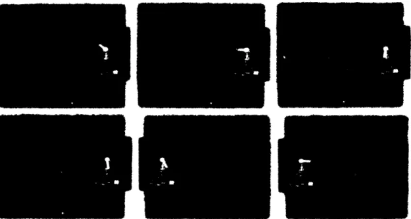
Figure 8: Various Impact Locations
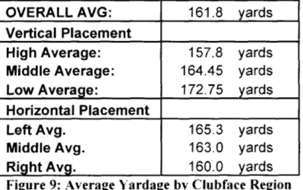
After carefully examining all of the pictures taken during the tests (displayed in the Appendix), the clubface was separated into nine regions, and the shots were categorized according to the strike location. The average power of each position was determined, and the results are shown in
impact. Hitting the ball in the center of the clubface produces a result that is slightly higher than the overall average yardage. The data shows that hitting the ball on the heel of the club, the lower
left, is extremely effective. This result can be attributed to anomalies. Most of the samples taken were hit around the center of the face. Therefore, poor shots and fantastic, rare shots were averaged out. Shots hit with other areas of the clubface were less common, and individual shots affected the average more.
OVERALLAVG: 161.8 yards
Vertical Placement
High Average: 157.8 yards
Middle Average: 164.45 yards
Low Average: 172.75 yards
Horizontal Placement
Left Avg. 165.3 yards
Middle Avg. 163.0 yards
Right Avg. 160.0 yards
Figure 9: Average Yardage by Clubface Region
There is a second factor that cannot be taken into account due to the setup of the tests. The Swing Groover 11 allows for the analysis of the accuracy of the hit but does not display its trajectory. It is possible that a Low-Left hit could travel 185 yards. However, it could have made it that far on the ground. Further tests are necessary to determine how the device accurately predicts the flight of the ball.
4.3 Accuracy
At this time, it is important to discuss the meaning of a straight shot in golf. In its broadest sense, a straight golf shot is one in which that ball travels in the air and lands a certain distance directly in front of the golfer. That is to say, a basic straight shot does not travel left or right of where it is aimed. This definition may be too constricting, however, because of the way a golf course is set
up. Figure 10 displays a typical golf hole. A golf hole consists of five main elements: the tee box, the fairway. the rough, the green, and hazards. Depending on the yardage of the hole, the goal of
the golfer is to hit the ball from the tee box and land on the fairway or the green. Any shot that accomplishes this is considered straight. As Figure 10 shows, the fairway usually takes uip most of the width of the golf hole. Any shot within the light green area would be considered a success. According to Northern California Golf Association, the average width of the fairways used in the 2000 U. S. Open tournament was 32 yards. This, of course, is a minimum since professional golfers are expected to be more accurate than the average player, and non-competitive courses will reflect this.
I ...
Figure 11: Fairway Analysis
If the professionals can hit a shot 5-10°and still be on the fairway, then, it is reasonable to assume that any shot hit up to 10°can be considered to straight.
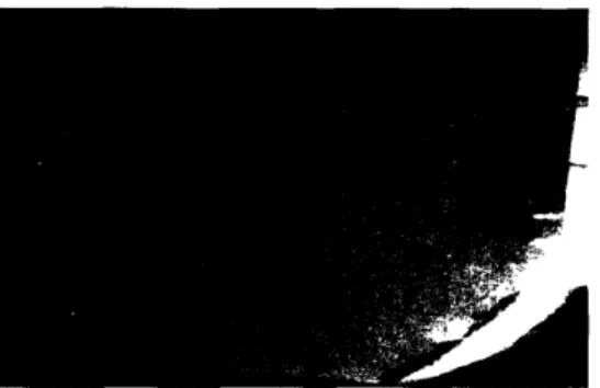
The Swing Groover 11 is capable of determining the accuracy of a golf shot up to thirty degrees in either direction. All of the sample shots taken consisted of either straight or sliced shots. This was a result of the test golfer's skill, but it also reflects the shot pattern of the typical amateur golfer. Amateurs are not known to hook the ball, i. e. make the ball drift left. but the cause of a hook could be determined by the same method that was used to investigate the sliced shots. There was a clear difference between some of the shots of varying accuracy. Two types of phenomenon were consistently present on the device as a result of a high angle slice: shear streaks and bubbling.
Shear streaks are particularly useful in analyzing a poor shot because they seem to indicate the angle at which the ball was hit. In a perfectly timed golf swing, the clubface will be normal to the ball at the point of impact. The shear streaks display the angle that the club head struck the ball and, therefore, are only present in sliced shots. A close uip picture of shear streaks is displayed below. I I I I I I I I I I I I I I I I I
Figure 12: Shear Streak Close Up
In Figure 12. it is evident that the indentation pattern points toward the bottom right of the clubface. This impression was made by a shot that was hit over 30° to the right. The ball flies to the right because at the moment of impact the clubface was at an angle. as the shear streaks suggest. The second type of accuracy related marking is referred to as bubbling. Bubbling is caused by the same missed shots as shear streaks.
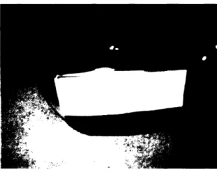
Figure 13: Bubbling Produced by a Slice
Bubbling is both welcomed and undesirable. It is the clearest sign of the result of a shot. The shear streaks can be difficult to observe, but bubbling is apparent because it actually changes the shape of the device. The club strikes the ball at an angle that causes the plastic layer of the device to push up, as displayed in Figure 13. This effect could be detrimental for the life of the product. however. The most common cause of failure during testing is the tearing of the top, plastic layer. Bubbling raises the plastic layer over the cardboard and exposes it to breaking. Making sure that the plastic layer lies perfectly against the cardboard will reduce risk of tearing and extend the device's life, but it will also reduce the amount of bubbling, which will make some shots harder to read.
Shear streaks and bubbling are the most apparent accuracy markers present in the tests, but these are not the only indentations that are useful to the golfer. A straight tee shot can leave as unique a mark as a bad slice. A straight shot is characterized by a perfectly round indentation on the device. Moreover, the dimples are distinct and circular as well, as observed in Figure 14.
Figure 14: Indentation Made by a Straight Shot
Even though the ball was struck on the edge of the face, it is clear that the indentation made is circular and a result of the club being completely normal to the ball. This denotes that the timing of the golfer's swing was just right. The most striking thing about the mark is the appearance of the dimples. Although dimples are common on the device, they are usually blended together. The dimples on a straight shot are distinct and perfectly circular. They also are consistent throughout the indentation. Another common phenomenon present in markings resulting from slices is a change in the shape of the dimples, denoting the angle at which the ball was hit.
Figure 15: Corrected Picture Showing Dimple Fading
The indentation on Figure 15 looks fine at first. The marking made is almost circular, and circular dimple impressions are present. However, they are not consistent throughout. The result of this shot was a 300 slice, the most severe that can be determined. Upon closer inspection, it is clear that the clubface did not strike the ball squarely. The indentation is defined at the top of the ball but fades toward the bottom. The ball was not struck at the center but at the top right, causing a slice.
The markings mentioned above are by no means the only indicators of a shot's accuracy. These are simply examples of how the accuracy of shots can be determined. The phenomenon above is simply the most notable and recurring throughout the testing phase.
4.3 Power
As shown in the preliminary test, the impression left from just tapping the device with the ball is smaller than the marking from a full shot. Therefore, it is reasonable to assume that the harder shot, the larger the impression will be. However, the device turned out to be inconclusive when
determining the power of the shot. This could simply be a result of using the same club and the yardage not varying greatly. In order to analyze the effect of indentation size on shot yardage, the size of the indentation in the photographs was normalized by dividing the marking diameter with the device length, and the ratio was plotted against the yardage of the shot. This graph is
presented below in Figure 16.
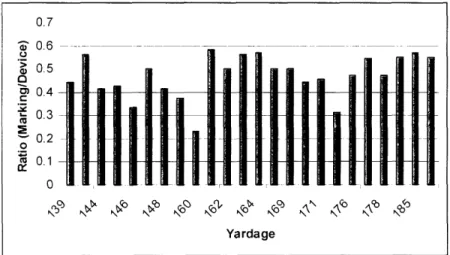
Figure 16: Graph of Power vs. Marking Size
The graph shov,,s that there is no direct correlation between the size of the indentation and the length of the shot. It is true that the shortest shot leaves a smaller indentation than the longest shot. but there is great variety in between. From this data, it can be postulated that the size of the indentation does not necessarily mean a longer shot. Figure 16 does seem to indicate that a large ball impression indicates a quality shot.
In Figure 16, shots of the same yardage are arranged in order of accuracy from left to right. There seems to be a trend on the graph that the most accurate shot of any given yardage generally produces the biggest, most clearly defined indentation. This is an interesting observation because it can be very useful to the golfer using the product. A big clear mark is easily identifiable and also satisfying. Therefore, a huge mark just means that good contact has been made, which is the goal of any golfer.
5.0 PRODUCT IN USE
The true test of any practice tool is whether it actually improves play. During the testing process, the shot statistics were recorded in order to compare it to indentations on the device, but another use for this data was found. By ordering the data in chronological order, the golfer was able to observe his improvement over time. A chart with all the shots and yardage achieved during these tests is displayed in Figure 17.
07 > 0.5 4 04 0.3
0.2 ...
'~ 01-Yardage250
200
+
150 * . . 100 __ ___ -50 0 0 10 20 30 40 50 Shot NumberFigure 17: Yardage Improvement Over Time
Figture 17 displays all of the shots and their yardage in chronological order. There is noticeable improvement in this chart. At the beginning of the testing, it was common to have tee shots that traveled less than 150 yards. Short yardage shots became rarer as testing went on, and the longer tee shots became more common. In fact, the last session of testing contained the two longest shots of the period. This improvement was achieved through observations made from the device. As the pictures in the Appendix show, there was a tendency for the golfer to hit the ball at the heel of the club. The only way that the golfer could have reliably learned this was through the use of the product. The golfer determined that either his stance was too far away from the ball I or he was over extending at the follow through. By the end of testing, the problem was still
prevalent. However, it was identified, and on the whole, the shots were higher quality.
Slicing was also rampant in the data. After observing this trend, the golfer tried to turn his wrist more quickly at the follow through to prevent the club head from opening at impact and caLlusing
a slice. There was also some improvement in this area, which is clear by the occurrence of straight shots toward the end of the testing. These details demonstrate the viability of the device as a practice tool. After an even longer period of use, it can be assumed that more problems could be identified and fixed.
6.0 CONCLUSIONS AND RECOMMENDATIONS
The modified Magic Pad was successfully used to record golf shots on the clubface. The device was successful because the indentations caused by the ball striking the clubface were clear and observable. They varied with the shot type and performance. The placement of the ball on the club face is easily determinable, but the accuracy and power of the shot can be harder to distinguish. Upon close inspection, some patterns do arise. The worst of shots leave skewed markings that include shear streaks and bubbling, but these do not become apparent until after close compariscon with shots of different qualities.
The advantage osf using this product is the relatively low cost compared to other golf equipment. The materials involved are just a few cents. The device lasts at least fifteen shots before the top
11 1
plastic layer tears. A profit could be made by selling the product at a penny a shot. Since driving ranges charge ten cents for every ball, the device would add very little cost to the price of practicing. and the device does not interfere with performance in a considerable way. Golfers would easily pay for the opportunity to know where their club is striking the ball. The
determination
of
the accuracy and power are bonuses, but such observations are clearly possible with this device. The most important result is that, in general, the best looking indentation is produced by the best shot. This makes it extremely easy and satisfying for the golfer using the device.Further development of the device should include doing away with the cardboard back of the device. If the device was thinner, it would affect performance less, and it could be used for all practices and even play. Since it often tears at the staples, a better binding strategy would also allow the device to have a longer life. It would also be helpful to include guidelines on the device. By separating the device into regions and providing guidelines to identify the angle impact. the result of the shot will be clearer to the golfer. and the product will be even more desirable.
7.0 APPENDIX
7.1 Supporting Mciterials
Dann, Jeremy 13. "Spalding: An Idea with Bounce." Technology Review. April 2005. Northern California Golf Association. "Inside the Ropes at the U. S. Open."
<http://www. ncga.org/turf/turf5.htm>
Brampton Technology Ltd. <http://www.bramptontechnology.com/index.html> Golf Encyclopedia Article. "The Golf Swing."
<http://search. Iocalcolorart.com/search/encyclopedia/GoIf/#The_golfswing> Picture Credits:
Figure 1. <http://www.paulwilsongolfcom/golfswingtechnique.htm> Figure 6 and 7. <http://www.amazon.com>
/71
Photographs of
Iclentations
on Device Face
The following pictures chronicle the markings produced on the device and offer descriptions on how to read the indentations.
r
Yardage: 119 Accur 51
Description: The low power of the shot and the slice create a skewed indentation.
Yardage: 146 Accuracy: Slice, 200 Clubhead Sneed: 63 Description: The marking clearly leans to the right and
confirms the slice.
Yardage: 160 Accuracy: Slice, 10U Clubhead Speed: 69 Description: Even though the device tore, a circular
indentation can be observed and reflects a relatively straight shot.
Yardage: 139 Accuracy: Slice, 30vClubhead Speed: 60 Description: The indentation clearly reflects a bad
slice because of its small, askew shape.
Yardage: 142 Accuracy: Slice, 20U Clubhead Speed: 61 Description: The shape of the indentation shows that the ball was
Yardage: 160 Accuracy: Slice, 10" Clubhead Speed: 69 Description: This shot clearly displays the variety of places
a shot could be hit from. Even though there is only half a mark on the device, it is clear that it is a round
and relatively straight.
Yardae: 171 Accuracy: Slice, 20°Clubhead Speed: 74 Description: This shot is more oval than round and reflects the high angle of slice. There is also some bubbling
Yardage: 187 Accuracy: Slice, 20°Clubhead Speed: 81 Description: This shot was the prime example of bubbling, and it shows the affect of dimple fading. The dark mark is a
result of a powerful hit.
Yardage: 169 Accuracy: Slice, 10" Clubhead Speed: 73 Description: The circular dimples reflect a relatively straight
shot. This shot continues the golfer's trend of hitting the
ball on the heel, which is apparent after some comparison.
Yardae: 148 Accuracy: Slice, 10" Clubhead Speed: 64 Description: The light mark reflects the low power of the shot.
-s >- tf-;Y-T4s
.~
Yardage: 148 Accuracy: Slice, 10" Clubhead Speed: 64 Description: This shot produced exactly the same result
as the previous one, and looks similar. The clearly defined dimples suggest a relatively straight shot.
Yardage: 167 Accuracy: Slice, 10" (Clubhead Speed: 72 Description: The marking is rounded but contains dimple
fading, which explains the slight slice.
Yardage: 176 Accuracy: Slice, 20°Clubhead Speed: 76 Description: This shot can be compared to the one above.
They were both struck at the same place, but the greater slice causes this marking to be less round. The extra
power also produces a darker indentation.
-Yardage: 162 Accuracy: Slice, 20u Clubhead Speed: 70 Description: This shot continues the heel tendency and Shows how the device eventually breaks at the binding,
Resulting in lighter indentations.
Yardage: 164 Accuracy: Slice, 10vClubhead Speed: 71 Description: This shot is skewed mostly vertically,
denoting the small amount of slice.
-I
F*. 4
Yardage: 176 Accuracy: Slice, 20°Clubhead Speed: 76 Description: This shot resulted in a reasonable slice, as
Yardage: 164 Accuracy: Slice, 30° Clubhead Speed:71 Description: This shot was shown as the perfect example of dimple fading. It is a dark mark, but it gets light on the
lower left, denoting the slice.
Yardage: 155 Accuracy: Straight Clubhead Speed: 67 Description: The round indentation indicates a straight
shot, but the small marking with bad placement resulted in low yardage.
Yardage: 142 Accuracy: Slice, 20°Clubhead Speed: 61 Description: This looks like good contact, which is inconsistent. However, the slight ellipse of the shape confirms that it was a slice.
Yarda e: 144 Accuracy: Slice, 30° Clubhead Speed: 62 Description: The marking on the device is clearly distorted. It starts off round at the bottom left but deforms signaling a massive slice. This can also be seen by the irregular dimples.
Yardage: 183 Accuracy: Slice, 30" Clubhead Speed: 79 Description: This was used as the example for shear streaks. The shot is powerful, which accounts for the clear indentation, but there are diagonal lines on the marking that show the slice.
Yardage: 185 Accuracy: Slice, 10" Clubhead Speed: 80 Description: The large, dark impression is a result of a powerful shot, but the askew dimples point to the slight
Yardae: 178 Accuracy: Sice, j3 vSlubhead peed: 77 Description: There is slight bubbling over the mark,
Flat top corner, and blending of the dimples; all signs
of a huge slice.
Yardage: 178 Accuracy: Slice, 30" Clubhead Speed: 77 Description: This yielded the same result as the shot
above, but the ball's more central strike location
produces a bigger mark.
Yardage: 160 Accuracy: Slice, 30" Clubhead Speed: 69 Description: The marking is clearly a result of a slice because of the elliptical shape and skewing of the dimples.
r __
1. - - .,
I - .. ...
Yardage: 169 Accuracy: Straight Clubhead Speed: 73 Description: This can be quickly determined to produce
a straight shot because of the round shape and uniform
dimples.
Yardage: 146 Accuracy: Slice, 20°Clubhead Speed: 63 Description: The partial marking on the device is caused
By a combination of low power and significant slice.
Yardage: 139 Accuracy: Slice, 30°Clubhead Speed: 60 Description: Once again, an amorphous shape and deformed
Yardage: 144 Accuracy: Slice, 20" Clubhead Speed: 62 Description: The poor shot resulted in askewed, asymmetrical
7.2 Shot Data Spreattsheet
Club head Speed (mph)
51 63 69 60 61 69 74 81 73 64 64 72 76 70 71 76 71 67 61 62 79 80 80 77 77 69 73 63 60 62 73 69 65 70 67 68 86 79 66 86 66 78 61 66 Shot Location Middle-Middle High-Right Middle- Left High-Right High-Middle Low-Middle Middle-Middle Low-Left Low-Left Middle-Middle Middle-Middle Middle-Left Middle-Left Low-Left Middle-Middle High- Middle Middle-Middle Low-Middle High-Middle High-Middle Low-Middle Middle-Middle Low-Left Middle-Left High-Middle Middle- Right Middle-Left High-Middle Middle-Left High-Left High- Middle Middle- Left Middle- Left Middle- Left High- Middle Middle- Middle Low- Left Low- Left High- Middle Middle- Middle Middle- Middle High- Middle Low- Left Middle- Left Shot Number 1 2 3 4 5 6 7 8 9 10 11 12 13 14 15 16 17 18 19 20 21 22 23 24 25 26 27 28 29 30 31 32 33 34 35 36 37 38 39 40 41 42 43 44 Yardage 119 146 160 139 142 160 171 187 169 148 148 167 176 162 164 176 164 155 142 144 183 185 185 178 178 160 169 146 139 144 160 151 164 162 155 158 199 183 153 199 153 180 142 153 ShotType SLICE SLICE SLICE SLICE SLICE SLICE SLICE SLICE SLICE SLICE SLICE SLICE SLICE SLICE SLICE SLICE SLICE STRAIGHT SLICE SLICE SLICE SLICE SLICE SLICE SLICE SLICE STRAIGHT SLICE SLICE SLICE SLICE SLICE SLICE STRAIGHT SLICE SLICE SLICE SLICE SLICE STRAIGHT SLICE SLICE SLICE STRAIGHT Angle 20 20 10 30 20 10 20 20 10 10 10 10 20 20 10 20 30 0 20 30 30 10 30 30 30 30 0 20 30 20 10 10 30 0 20 10 20 30 20 0 30 10 30 0 _ _._