Development of an Incremental and Iterative Risk Reduction
Facility for Robotic Servicing and Assembly Missions
by
David Charles Sternberg
S.B. Aerospace Engineering (Course 16-1) Massachusetts Institute of Technology (2012)Submitted to the Department of Aeronautics and Astronautics in partial fulfillment of the requirements for the degree of
Master of Science in Aeronautics and Astronautics at the
MASSACHUSETTS INSTITUTE OF TECHNOLOGY June 2014
© 2014 Massachusetts Institute of Technology. All rights reserved.
Author... Department of Aeronautics and Astronautics
May 22, 2014
Certified by... David W. Miller Professor of Aeronautics and Astronautics Thesis Supervisor
Certified by... Alvar Saenz-Otero Director of Space Systems Laboratory Thesis Supervisor
Accepted by... Paulo C. Lozano Associate Professor of Aeronautics and Astronautics Chair, Graduate Program Committee
2
Development of an Incremental and Iterative Risk Reduction
Facility for Robotic Servicing and Assembly Missions
by
David Charles Sternberg
Submitted to the Department of Aeronautics and Astronautics on May 22, 2014, in partial fulfillment of the
requirements for the degree of
Master of Science in Aeronautics and Astronautics
Abstract
A means for reducing the risk for an on-orbit robotic servicing and assembly mission through the development of a series of testbeds that build successively upon one another is investigated. Robotic Servicing and Assembly (RSA) missions are believed to enable life extension programs for existing spacecraft while also enabling much larger and more complex satellites to be developed through on-orbit construction. Unfortunately, many of the new and innovative technologies required for RSA to be economically and technically feasible are still in their formative development stages. Consequently, such RSA missions are highly risk prone.
This thesis investigates the development of an incremental and iterative testing facility which can be used to reduce these RSA risks by conducting demonstration testing in authentic operational environments while leveraging existing infrastructures to reduce the costs associated with testing. The Defense Advanced Research Project Agency’s (DARPA) Phoenix project, a satellite repurposing mission, serves as an example of a full-scale flight mission requiring risk-reduction testing. The thesis presents research that shows how the newly developed testing facility, which expands on the Synchronized Position Hold Engage and Reorient Experimental Satellites (SPHERES) facility, can reduce the risk of many technologies required for Phoenix. In particular, testing is discussed and analyzed for the risk reduction of resource aggregation and physical reconfiguration technologies.
This testing is both incremental and iterative in nature as part of two ground test programs and a flight program aboard the International Space Station. The testing progression matures these technologies from base principles tested in the ground environment at the MIT Space Systems Laboratory to the planned implementation aboard the International Space Station prior to the final flight mission. The newly developed testing facility is small in scale as compared to the final RSA flight satellites, so newly developed scaling laws are presented. This process relies on the scaling of testbed results using the combined application of hybrid scaling laws and nondimensional parameters. In doing so, the results from the new testing facility can be applied to the Phoenix mission to raise the probability of mission success.
Thesis Supervisor: David W. Miller
Title: Professor of Aeronautics of Astronautics Thesis Supervisor: Alvar Saenz-Otero
3
Acknowledgments
There are innumerable individuals and groups who have helped make this thesis possible. First and foremost, I am forever indebted to my family and grandparents for their ever-constant support in all of my endeavors. You have shaped my education and career in ways that are just beginning to be comprehended, and I will always love you. You have done so many things for me, and I hope that this thesis is another way for me to show my appreciation. My friends have also stuck with me through both the good and bad times. While many undergraduate peers dispersed after graduation throughout the country, Angelica Ceniceros, Jesus Zuniga, Gina Noh, Zoe Rogers, and Tess Smidt have remained unwavering friends. I am especially grateful for the continued friendship of Pearle Lipinski through my graduate experience thus far at MIT. Of course, I will never forget the other members of the SPHERES team, particularly those of the original AMP team, the Wolf Pack: Chris Jewison and Bryan McCarthy. I eagerly look forward to working with Chris, the other SPHERES team members, and the rest of the SSL in the coming years as a doctoral student. Lastly, I would like to say that I am deeply honored to work with Dr. Alvar Saenz-Otero and Prof. David Miller. Their seemingly limitless knowledge and instructional capacity has paved the way for me to transition from freshman UROP to graduate student on the SPHERES team.
The work performed and detailed in this thesis was financially supported by several organizations, and I am deeply grateful for their support. The National Aeronautics and Space Administration (NASA) and the United States Air Force Space and Missile Systems Center (SMC) supported the Agile Reconfigurable Modules with Autonomous Docking for Assembly and Servicing (ARMADAS) project under NASA Contract #NNH11CC25C. Additionally, Aurora Flight Sciences (AFS), NASA, and the Defense Advanced Research Projects Agency (DARPA) supported the InSPIRE II program though NASA Contract #NNH11CC26C and the Phoenix projects under DARPA-BAA-13-12.
4
1
Table of Contents
Abstract ... 2 Acknowledgments... 3 List of Figures ... 6 1 Chapter 1 – Introduction ... 101.1 Motivation: Robotic Servicing and Assembly (RSA) and the DARPA Phoenix Project, Testbed Development, and Scaling ... 10
1.2 Development Process Overview and Rationale ... 16
1.3 Literature Review and Research Gap Analysis ... 18
1.4 Thesis Research Questions ... 33
1.5 Thesis Roadmap ... 34
2 Chapter 2 - Determine RSA Testbed Requirements ... 37
2.1 Summary of Requirement Definition Process ... 37
2.2 Testbed Traceability ... 38
2.3 Leverage Existing Infrastructure ... 39
2.4 Incremental, Iterative Testing Opportunities ... 40
3 Chapter 3 – Create or Modify a Testbed ... 42
3.1 Make or Buy Decision ... 42
3.2 SPHERES Testbed ... 45
3.3 SWARM Components ... 50
3.4 ISS Flight Hardware ... 52
3.5 Summary of Final RSA Testbed Design ... 59
4 Chapter 4 – Incremental Testing of RSA Technologies ... 63
4.1 Introduction to Testing Process ... 63
4.2 Test Unknown Dynamics in 1g ... 66
4.2.1 Phase I Testing: Rotation Control ... 67
4.2.2 Phase II Testing: Tipoff Control in 1g ... 71
4.2.3 Unknown Dynamics in 1g Conclusion ... 78
4.3 Test Path Planning and Changing Dynamics in 1g ... 79
4.3.1 Resource Aggregation ... 80
4.3.2 Reconfigurable Control ... 82
4.3.3 Autonomous Path Planning... 84
5
4.3.5 RARC and Path Planning Increment Results... 89
4.3.6 Path Planning and Changing Dynamics in 1g Conclusion ... 96
4.4 Test Multi-Vehicle Dynamics in 0g ... 97
5 Chapter 5 – Scalability of Test Results ... 103
5.1 Review of Buckingham Pi Theorem and Dimensional Homogeneity ... 103
5.2 Scalability Factors ... 106
5.3 Hybrid Scaling of Testbed Parameters ... 107
5.4 Combination Process for Nondimensional Hybrid Modeling ... 110
5.5 Scaling of Existing and New Pi-Numbers ... 114
5.6 Control Law Scaling ... 118
5.7 SPHERES Simulation Implementation ... 126
6 Chapter 6 - Conclusion ... 132
6.1 Summary of Thesis Results ... 132
6.2 Limitations of Research ... 133
6.3 Research Contributions ... 135
6.4 Future Work ... 135
6
List of Figures
Figure 1: On-Orbit Telescope Assembly Process (Mohan, 2010) ... 11
Figure 2: Current RSA Task Confidence (Moyer and Mauzy, 2011) ... 13
Figure 3: Artist Conception of DARPA Phoenix Mission ... 14
Figure 4: Diagram of Satlet Concept (Barnhart, 2012) ... 19
Figure 5: Projected Impact of Cellularized Spacecraft on Mission Cost (Barnhart, 2012) ... 20
Figure 6: Proposed 2015 Fractionated Spacecraft Demonstrations (Eremenko, 2011) ... 22
Figure 7: Space Harbor Concept [Top], Corresponding Servicing Concept [Bottom] (Horsham, 2010) ... 23
Figure 8: Proposed Micro-Satellite On-Orbit Servicing Platform (Wang, 2013) ... 24
Figure 9: Robotic Construction Crew and Lemur IIa (Stroupe, 2005) ... 25
Figure 10: Mini AERCam External View (Fredrickson, 2003) ... 26
Figure 11: Formation Control Testbed and Formation Algorithms Simulation Testbed (Sohl, 2005) ... 27
Figure 12: Ground Floating Beam Docking Demonstration (Barnhart, 2009) ... 27
Figure 13: Motor Scaling Law Based on Output Torque (Dermitzakis, 2011) ... 30
Figure 14: Replica, Multiple, and Hybrid Scaling Geometry (Gronet, 1989) ... 32
Figure 15: Orbital Express Mission Concept of Operations Diagram (Shoemaker, 2003) ... 33
Figure 16: Thesis Roadmap ... 35
Figure 17: ISS Testing Environmental Conditions (Adapted from Halo System Requirements Document, 2013) ... 41
Figure 18: Make/Buy Decision Flowchart (Padillo, 1999) ... 43
Figure 19: Risk Categories (Cardin, 2010) ... 44
Figure 20: A SPHERES Satellite ... 47
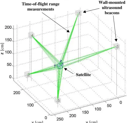
Figure 21: SPHERES Metrology System (Mohan, 2010) ... 48
Figure 22: SPHERES Expansion Port V2 ... 49
Figure 23: SWARM Hardware (ARMADAS Test Results, 2013) ... 51
Figure 24: Labeled Halo System... 54
Figure 25: Halo System Mounted on SPHERES/VERTIGO Assembly ... 54
Figure 26: Functional Halo Prototype ... 55
Figure 27: SolidWorks Model of UDP with Protective Pieces Installed ... 56
Figure 28: SolidWorks Model of UDP with VERTIGO Avionics Stack Standoff ... 56
Figure 29: UDP Prototype Mounted to VERTIGO Avionics Stack (Photo Credit: Duncan Miller) ... 57
Figure 30: Two UDPs Mounted to Halo ... 59
Figure 31: RSA Testbed Testing Increments ... 65
Figure 32: First Testing Increment Hardware Setup (Phoenix Testing Summary, 2013) (Photo Credit: David Sternberg) ... 68
Figure 33: First Testing Increment Schematic (Phoenix Testing Summary, 2013) ... 69
Figure 34: Angular Displacement vs. Time (Asymmetric Case) for Phase I Testing (Phoenix Testing Summary, 2013) ... 71
Figure 35: Time Response and Tracking Error to Step Input for Direct Adaptive Controller (Phoenix Testing Summary, 2013) ... 73
Figure 36: Time Response and Tracking Error to Step Input for Direct Adaptive Controller with Doubled System Mass, but Controller has No A Priori Mass Change Knowledge (Phoenix Testing Summary, 2013) ... 74
Figure 37: Reference Model and Z-Axis Rotation Rate: Test 1b (Phoenix Testing Summary, 2013) ... 77
Figure 38: Reference Model and Z-Axis Rotation Rate: Test 2b (Phoenix Testing Summary, 2013) ... 77
Figure 39: Reference Model and Z-Axis Rotation Rate: Test 3b (Phoenix Testing Summary, 2013) ... 78
Figure 40: Reference Model and Z-Axis Rotation Rate: Test 4b (Phoenix Testing Summary, 2013) ... 78
Figure 41: Example RARC Business Card Contents (ARMADAS Test Results, 2013) ... 81
Figure 42: Diagram of RARC Business Card Communication (ARMADAS Test Results, 2013) ... 82
Figure 43: p-Sulu to SPHERES Satellite Communication Architecture (ARMADAS Test Results, 2013) ... 86
Figure 44: Top-down view of test area where (1) is the p-Sulu path-planning phase (2) is the docking phase (3) is a RARC translation and (4) is a RARC rotation (ARMADAS Test Results, 2013) ... 87
Figure 45: Simulated SPHERES Satellite State Data over Multiple p-Sulu Trials (ARMADAS Test Results, 2013) ... 90
7
Figure 47: Multiple primary SPHERES Satellite Trajectories Following Fixed Horizon p-Sulu Waypoints
(ARMADAS Test Results, 2013) ... 92
Figure 48: Comparison of Actual (Blue) vs. Expected (Green) Response Curves to 0.5m Step Input (ARMADAS Test Results, 2013) ... 94
Figure 49: Comparison of Actual (Blue) vs. Expected (Green) Response Curves to 180 Degree Step Input (ARMADAS Test Results, 2013) ... 95
Figure 50: Actual Angular Response Curves over Multiple Testing Iterations (ARMADAS Test Results, 2013) 96 Figure 51: Tradespace of On-Orbit RSA Testing Demonstrations ... 100
Figure 52: Scaling of RSA Satlet to SPHERES Satellite Using Hybrid Scaling Parameters ... 110
Figure 53: SPHERES Satellite on SWARM Propulsion Unit Scaling Schematic ... 112
Figure 54: Docked Halo Scaling Schematic ... 112
Figure 55: Newton Number as a Function of ... 116
Figure 56: Example Basic Control Loop ... 119
Figure 57: Transient Response Properties (Ogata, 2010) ... 122
Figure 58: Step Response for Position Control with Original and Scaled Inputs ... 124
Figure 59: Step Response for Attitude Control with Original and Scaled Inputs ... 125
Figure 60: Effect on Step Response: Scaling of Control Gains and Physical Parameters in the SPHERES Simulation ... 128
Figure 61: Scaled Controller Step Response Parameters from SPHERES Simulation ... 129
Figure 62: Step Response Parameter Ratios for Simulated Scaled Satellite to SPHERES Satellite ... 130
8
List of Tables
Table 1: Technology Readiness Levels (Wertz, 2011) ... 17
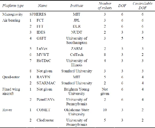
Table 2: Existing Testbeds for Distributed Space Systems (Chu, 2013) ... 45
Table 3: SPHERES Satellite Physical Properties... 47
Table 4: Principal Halo Properties... 62
Table 5: Principal UDP Properties... 62
Table 6: Initial Rates and Total Rotations during Phase II Testing ... 76
Table 7: Possible On-Orbit Tests with the RSA Risk Reduction Facility ... 101
Table 8: Hybrid Model Equivalents for Common Physical Parameters ... 108
Table 9: Expected Scaling Parameters for Docked Halo System ... 113
Table 10: Common Nondimensional Parameters from Multiple Disciplines (Schuring, 1977) ... 117
Table 11: Common Nondimensional Parameters from Dynamics (Kunes, 2012) ... 118
Table 12: Scaling of Strain Energy (Crawley, 1990)... 121
Table 13: Transient Response Properties (Ogata, 2010) ... 123
Table 14: Position and Attitude Control Step Response Scaling Results ... 125
9
Key Nomenclature
AFS Aurora Flight Sciences
ARMADAS Agile Reconfigurable Modules with Autonomous Docking for Assembly and Servicing
ATLAST Advanced Technology Large-Aperture Space Telescope
CAD Computer Aided Design
DARPA Defense Advanced Research Projects Agency
DOF Degrees of Freedom
ExpV2 Expansion Port Version 2
GEO Geosynchronous Earth Orbit
GSP Guest Scientist Program
HL/FFS Hybrid Length/Force Frequency Strain
ISS International Space Station
MIT Massachusetts Institute of Technology
NASA National Aeronautics and Space Administration
RARC Resource Aggregated Reconfigurable Control
RINGS Resonant Inductive Near-Field Generation System
RSA Robotic Servicing and Assembly
SMC United States Air Force Space and Missile Systems Center
SPHERES Synchronized Position Hold Engage and Reorient Experimental Satellites
SSL Space Systems Laboratory
SWARM Self-assembling Wireless Autonomous Reconfigurable Modules
TRL Technology Readiness Level
UART Universal Asynchronous Receiver/Transmitter
UDP Universal Docking Port
10
1
Chapter 1 – Introduction
1.1 Motivation: Robotic Servicing and Assembly (RSA) and the DARPA Phoenix Project, Testbed Development, and Scaling
The demand for on-orbit servicing and assembly capabilities has been increasing as space systems grow in size, complexity, and capability scope. There already are several projects which will utilize new robotic servicing and assembly (RSA) technologies. For example, the Optical Testbed and Integration on ISS eXperiment (OpTIIX) program, a joint project between the National Aeronautics and Space Administration (NASA) Jet Propulsion Laboratory, Goddard Space Flight Center, Johnson Space Flight Center, and the Space Telescope Science Institute, aims to assemble a 1.5m telescope aboard the ISS robotically. This demonstration would require moving beyond simple formation flight control into the realm of resource aggregated reconfiguration. Another telescope project which will rely heavily on RSA technologies is NASA Goddard’s Advanced Technology Large-Aperture Space Telescope (ATLAST) program, which plans to develop a highly scalable architecture suite for assembling telescopes much larger than currently feasible by exploiting new RSA technologies and economies of scale. On-orbit assembly of large space telescopes reduces risks and overcomes difficulties associated with launch vehicle constraints, integration and testing cycle times, servicing and maintenance capabilities, and ground testing constraints. Figure 1 shows an example of an on-orbit assembly process which relies on satellite reconfiguration and assembly technologies yet to be fully developed.
11
Figure 1: On-Orbit Telescope Assembly Process (Mohan, 2010)
The function of on-orbit servicing can be applied to spacecraft already in orbit today because servicing enables the repair or replacement of components, subsystems, and fuel or cryogenics to extend the operational lifetime of a satellite system. Additionally, the ability to conduct on-orbit servicing can enable the deorbiting or end of life disposal of defunct satellites which cannot be repaired back to a fully operational status or those which are no longer economically viable. Servicing techniques have been explored with humans in Low Earth Orbit, but little has been tested with respect to fully robotic servicing. Further discussions can be found in Guo (2009), Wang (2013), Fredrickson (2003), Reintsema (2012), and in Section 1.3.
The function of on-orbit assembly, however, can primarily be applied to spacecraft yet to be launched, since on-orbit assembly typically entails designing a system to be assembled from the start of a space project. There are many advantages, though, which counter the required added design effort. On-orbit assembly enables the launch of satellites which could not be nominally launched monolithically. Launch vehicle constraints drive most of the structural design requirements for space systems. The ability to assemble multiple modules reduces the direct impact of these launch vehicle constraints, since the spacecraft can be launched in multiple pieces and subsequently assembled on-orbit. Consequently, spacecraft can be developed that would never have been feasible without assembly capabilities. Furthermore, the assembly process and multiple-launch sequence
12
enables the development of staged deployment of system capabilities. Launches after the spacecraft begins operations can provide upgrades or additions to the spacecraft, such as new or improved instruments, actuators, or sensors. The expansion of a spacecraft’s functionality over time increases the productivity and return on investment, improving the spacecraft’s net worth. The decision to launch these upgrades based on need or on a fixed schedule can be treated as an architectural decision during the spacecraft system design process, thereby increasing the potential versatility of the system as a whole. Further discussions of on-orbit assembly can be found in Barnhart (2009), Guo (2009), Chu (2013), Mohan (2010), and in Section 1.3.
When combined with on-orbit servicing technologies, on-orbit assembly technologies become even more potent in their ability to shape future space system architectures. Combining the two into a complete RSA system enables multiple space system architectures which are much more robust to changing operating environments and performance demands. The life of each satellite can be changed drastically over time, and with the advent of modularity and fractionation, concepts to be discussed in Section 1.3, multiple reconfigurations of a satellite can enable near optimum functionality across a range of performance levels for comparably lower costs.
Unfortunately, robotic, on-orbit servicing and assembly missions entail extensive risk. As a direct result of multiple spacecraft operating in close proximity to one another, multiple elements with independent control laws must operate with very tight constraints on their physical boundaries. Further, it is very difficult to test all possible multi-satellite configurations on the ground with existing testbeds, since there are limitless possibilities of how satellites can be oriented and positioned relative to one another. Since each of these satellites is able to function independently from one another, there is an omnipresent risk of collision and damage which would result in the partial or complete loss of space elements. Moyer and Mauzy (2011) have outlined a high-level description of the various tasks that are required for robotic servicing and assembly and the current confidence in each, shown in Figure 2. The level of confidence is inversely proportional to the level of autonomy for each particular capability. For future robotic servicing and assembly missions, the authors state that it is desired to incorporate as much autonomy as possible into the system to enable new, more complex mission goals. Further, the capability of internal component
13
replacement is crucial for extended missions; the figure shows how no level of autonomy currently provides full confidence in mission success across all mission modes. The RSA testbed developed in this thesis can be used to reduce the risks associated with such tasks in order to enable mission architectures that currently require in-situ human action. The figure therefore shows the need for risk reduction as a whole for complex servicing and assembly on orbit. A new testbed is required to reduce the risks associated with these tasks in order to improve the confidence in robotic capabilities and enable RSA flight missions.
Figure 2: Current RSA Task Confidence (Moyer and Mauzy, 2011)
The DARPA Phoenix Program plans on cooperatively harvesting and re-using already existing, retired, non-operating satellite components in geostationary graveyard orbit to demonstrate the capability of creating new space systems for significantly decreased costs. To accomplish this goal, the Phoenix program aims to rely on a new type of spacecraft system called a satlet. According to Barnhart (2012), a satlet is a small spacecraft with only a small fraction of the functionality of a complete satellite. In order to create a new satellite, an aggregate of multiple satlets is required. This key enabling technology is termed cellularization, and is a measure of how functions are distributed across multiple satlet types. An artist’s interpretation of a servicer spacecraft placing a satlet on an aperture in the Geosynchronous Earth Orbit (GEO) graveyard orbit is shown in Figure 3. The aggregation of multiple satlets into a single aggregate with full satellite functionality is a
14
clear demonstration of on-orbit assembly technologies, and the need to repurpose already existing on-orbit hardware is similarly a clear example of the application of on-orbit servicing technologies. The DARPA Phoenix Program is therefore a prime example of a mission still under development which will rely heavily on RSA technologies that are still in their formative development stages. As such, Phoenix is a high risk demonstration of many new technologies, including multi-satellite proximity control, autonomous docking and undocking, and autonomous reconfiguration. Consequently, there exists a need for extensive testing to raise the probability of mission success, necessitating a directly traceable and scalable, low cost testbed.
Figure 3: Artist Conception of DARPA Phoenix Mission
To demonstrate all of these elements in concert to reduce risk, there is a requirement for a demonstration in an authentic operational environment for the risk reduction of the various key technologies. All technology risk-reduction processes have inherent challenges, but in order to test a technology fully, it is important to test to failure in an authentic environment in order to understand what makes each technology element brittle. With this understanding, it is possible, then, to make improvements to the technologies. Even the process of integrating all of the technologies into a single demonstration imposes some risk. Consequently, a risk reduction testbed is required prior to the Phoenix mission.
Testing aboard the International Space Station (ISS) can provide significant risk reduction if coupled with ground testing. The ISS provides the authentic operational environment of extended microgravity, the most pertinent aspect to the subelements of the
15
problem associated with RSA operations. Therefore, the combination of ISS testing with initial ground testing with a testbed that is operable in both environments can significantly reduce RSA risks for low cost. The development of such a testbed requires careful requirement definition in order to reduce RSA risks at low costs. This process is further discussed in Chapter 2.
Multiple testbeds already exist for reducing risks associated with on-orbit operations, including the risk reduction of many RSA technologies themselves. Servicing and assembly missions require extensive development of proximity operations algorithms, for example, and air bearings and micro-air-vehicles around the world have conducted fundamental and developmental research for such risk reduction. Further discussion of these existing testbeds is described in Section 1.3 and in Section 3.2.
Conducting a test sequence, as would be created through a design of experiments analysis, requires scaling a final system (typically down in scale for space systems) so that meaningful test data can be obtained on the ground or on-orbit with test articles representative of what will be eventually flown on the final mission. Each system usually has several thousand requirements that must be met in order for the mission to be successful. Of the standard methods for requirement verification (analysis, demonstration, testing, inspection, and similarity/analogy to prior systems), testing is one of the most common and informative. Unfortunately, the bulk of testing occurs near to final hardware delivery for launch: if delays occur early in the development process, testing is usually reduced to stay on time and financial budgets. There is a clear need, therefore, for time and cost efficient testing.
In an effort to make the most of risk-reduction tests, it is best to conduct a sequence of tests which build upon one another so that the full system’s operability is demonstrated incrementally. Doing so provides a clear path through the system of known operation modes and capabilities, helping to pinpoint design or development errors prior to full system integration. The corresponding costs associated with a slow-paced fully incremental testing process, however, prevent a system from ever being completely tested. A properly designed testbed and testing strategy is required for optimal risk reduction. Starting with the design of the testbed itself, the testing process can make use of existing infrastructure for cost reduction purposes, and the test articles can be designed to reduce multiple risks.
16
For example, it is rarely required to build a structure specifically for vibro-acoustic testing and to build a separate structure specifically for determining the fundamental oscillatory modes of the spacecraft: the same structure could potentially be used in both tests. Similarly, if there are differences between testbeds, significant effort should be placed into ensuring that they are as similar to each other as possible in scale.
The scaling of testbeds has been addressed through engineering modeling, and is discussed further in Section1.3. It is important to note the scale of each testbed, since only through testing with testbed-specific scaling laws can the behaviors be compared across multiple testbeds and be applied to the final, full-scale flight system. The final system is termed full-scale because it consists of the hardware and software that will be launched. Certain components, subassemblies, or subsystems may be too small to test easily; these elements usually are scaled up, increasing their size above that of the final elements. Other elements, however, cannot be tested without decreasing their size, so scaling down to create representative smaller elements is required to enable testing. This scaling process is imperfect, since a scaled system cannot behave identically to the original, non-scaled system. Using scaling laws developed specifically for a given scaled system, however, can solve this and other related issues. Further analysis on this topic is discussed in Sections 1.3 and 2.2, and in Chapter 5.
1.2 Development Process Overview and Rationale
The process for creating an incremental and iterative testbed for risk reduction requires the knowledge of the final flight system and the principal risk areas that require risk reduction. This knowledge comes from the development of the flight project itself. Early in the design phase, such as during the standard NASA Pre-Phase A through Phase A periods, high level concepts are discussed for determining characterization of the flight mission. While feasibility concepts are discussed, little emphasis is traditionally placed on the risk reduction strategies which will inevitably be necessary in later design phases, such as Phase B and Phase C. Consequently, the mission concept definition typically specifies the technologies which eventually will be incorporated into the final mission architecture, but not the means for maturing the technologies to flight readiness.
The technologies engaged in flight missions often span a range of Technology Readiness Levels, or TRLs. These levels range from 1 to 9 as a means of defining the
17
maturity of a given technology or system. Table 1 shows a sample definition for each Technology Readiness Level as defined by Wertz (2011).
Table 1: Technology Readiness Levels (Wertz, 2011)
Technology Readiness Level Definition
1 Basic principles observed and reported.
2 Technology concept and/or application
formulated.
3 Analytical and experimental critical function
and/or characteristic proof of concept.
4
Module and/or subsystem validation in a laboratory environment (i.e., software prototype development environment).
5 Module and/or subsystem validation in a
relevant environment.
6 Module and/or subsystem validation in a
relevant end-to-end environment.
7 System prototype demonstration in an
operational, high-fidelity environment.
8
Actual system completed and mission qualified through test and demonstration in an
operational environment.
9 Actual system proven through successful
mission-proven operational capabilities.
TRLs are useful for correlating the components and subsystems that comprise a full system with system risks. For example, a system comprised of components with lower TRLs on average will generally have higher associated technical risks than a system composed of on average higher TRL components because of the inherent lack of component maturity. The testbed development process is crucial in lowering risks associated with technologies which are low TRL and are still in their formative development stages.
This thesis discusses the methodology for creating a new, incremental, and iterative testbed for reducing the risks associated with RSA technologies with the DARPA Phoenix program as the principal case study. As such, the thesis focuses on four major steps: determine testbed requirements, create or modify an existing testbed, conduct incremental testing, and scale test results. This four step process is used to determine the most appropriate testbed to develop in order to mitigate the most risk for the least associated
18
costs, both in terms of time and money. Dr. Alvar Saenz-Otero discussed in his 2005 thesis a series of testbed design principles. These seven guiding principles provide a basis upon which to devise new testbeds for remote operation. The four step process described here applies these seven principles to the task of RSA technological risk reduction.
1.3 Literature Review and Research Gap Analysis
The development of a new testing facility for the risk reduction of key, formative stage RSA technologies started with a comprehensive literature review to determine the existing research in related fields. Additionally, the literature review was able to demonstrate that a gap exists in the current literature that necessitated the research presented in this thesis in order to develop the risk reduction testbed properly.
The literature review focused on the three principal areas of cellularized and fractionated spacecraft, on-orbit robotic servicing and assembly, and testbed development and scaling laws. These three major research areas have each enjoyed significant research focus over the past several years as missions have become more capable and the concept of RSA missions has gained traction in the astronautical community. Little research, however, has attempted to integrate the fields together, necessitating the research presented in this thesis, which serves as a union of the research areas to enable the development of RSA testbeds that are traceable and scalable to the final flight missions.
One of the most relevant research areas in the field of cellularization and fractionation of spacecraft has been performed by David Barnhart (2012). The author provides an overview of the DARPA Phoenix mission, a project aimed at the repurposing of hardware already in place within the Geosynchronous Earth Orbit (GEO) graveyard orbit. Repurposing hardware requires technologies associated with both servicing and assembly, since the existing on-orbit hardware must be brought to an operational status with new mission goals with new hardware elements. To do so, several spacecraft are required, including a large servicer/tender satellite and a multitude of small satlets. Barnhart describes satlets as small satellites without complete, full satellite capabilities that are created using the process of cellularization. Cellularized satlets each have a small amount of the functionality of a complete satellite because cellularization is a measure of how functions are distributed among satlet types. Effectively, satlets are the embodiment of the physical decomposition of a monolithic satellite into multiple separate modules. Each satlet
19
is considered to be a separate, indivisible, self-sustaining unit, capable of: physically mounting to other satlets or servicing spacecraft, communication with other satlets, command processing, health management, thermal management, and power management. Figure 4 shows an example of how Barnhart envisions this decomposition: the multiple functions of a monolithic satellite can be attained through the aggregation of multiple satlets of multiple satlet types on orbit.
Figure 4: Diagram of Satlet Concept (Barnhart, 2012)
The process of aggregation enables multiple satlets to form a cohesive unit that can operate together to perform a given mission task. This method for satellite construction, therefore, enables the aggregated system: to minimize repeated functionality between modules when attempting to assemble a specific satellite or meet certain performance goals, to provide partial functionality in a servicing scenario when attempting to replace or create certain capabilities on the spacecraft being serviced, and to maintain a clear internal understanding of what capabilities can be created with a given suite of satlets. For example, a servicer/tender satellite might have a certain compliment of satlets that can be used to conduct a servicing mission of one type, but not have the appropriate satlets to perform another. As a result, a different servicer/tender would need to be called upon to complete the mission with a different set of satlets. This variability between which satlets are available to a given servicer/tender increases the architectural design space as to the servicing and assembly missions that may be undertaken.
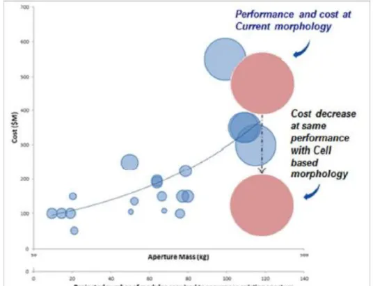
RSA missions themselves are a crucial extension of current capabilities in order to continue the economic development of the space industry. In the same paper, Barnhart describes how the concept of cellularized satlets can reduce the cost of repurposing missions. Figure 5 shows the projected impact that cellularization will have on the cost of a
20
mission to repurpose an aperture of a given mass from the GEO graveyard orbit. Importantly, though the figure centers on repurposing, Barnhart writes that being able to achieve performance goals with satlets to avoid unnecessary performance overlap between satlets and being able to launch a large number of satlets to perform either on-demand or scheduled servicing to take advantage of economies of scale cost benefits are fundamental beneficial attributes of cellularization that can be extended to other RSA missions beyond Phoenix.
Figure 5: Projected Impact of Cellularized Spacecraft on Mission Cost (Barnhart, 2012)
A related technology concept to cellularization is that of fractionation (Guo, 2009) (DuBos, 2011). As explained in Brown (2006) fractionation is “the decomposition of a spacecraft into modules which interact wirelessly to deliver the capability of the original monolithic system, allowing system flexibility, maintainability, scalability, and reconfigurability”. Therefore, fractionation provides a portfolio of modules based on the physical decoupling of components to reduce system fragility through distribution across multiple modules. Like cellularization, fractionation seeks to reduce mission costs through maintaining contractor diversity and application of learning curves to the manufacturing costs of each module. The DARPA F6 (Future, Fast, Flexible, Fractionated, Free-Flying
21
Spacecraft) program was the first heavily researched mission to utilize the fractionation of spacecraft. A multitude of papers have been written on the F6 program, including Brown (2008), Eremenko (2011), Brown (2006), and Brown (2009). A more recent fractionated spacecraft program that has been proposed is the Pleiades system in the paper by LoBosco (2008). These papers acknowledge that there are many technologies which require extensive testing and verification prior to implementing a fully fractionated spacecraft system. Such technologies include cluster or formation flight, data transmission, fractionated navigation systems, distributed capabilities and data resources, and the transmission capabilities of power, force, and torque.
An example of a potential on-orbit demonstration sequence that relies on these technologies is shown in Figure 6, as proposed in Eremenko (2011). Unfortunately, there is no testing sequence in place to reduce the risks associated with these demonstrations. The demonstrations have no ground testing or intermediate microgravity testing planned despite the large number of novel, untested technologies. Consequently, the four demonstrations described in the figure are currently only conceptual; additional research and development into these four multi-satellite technology demonstrations is required prior to implementation on-orbit.
22
Figure 6: Proposed 2015 Fractionated Spacecraft Demonstrations (Eremenko, 2011)
Horsham (2010) has proposed another type of RSA mission architecture that is focused on what is called a space harbor. In this paper, a space harbor transport facility for a fleet of robotic servicing spacecraft is described. This satellite system includes separate facilities for a sate command, communication, and control system, a parts station, a fuel station or depot, and a fuel/parts replenishment transport vehicle system. Figure 7 shows an artist’s image of what the space harbor could look like, including an octagonal truss section for the docking and undocking of all servicing satellites and fuel or replacement component pods. This vision likely will not be implemented in the near future because of the lack of research into many of the required enabling technologies. The authors do not propose any risk mitigation strategies, nor do they propose a detailed mechanism for the on orbit assembly of their space harbor, though they do make use of existing spacecraft structures, exemplified by the use of truss elements from existing space stations. Many of the technologies required for the success of the space harbor will necessitate thorough testing and risk reduction, since the space harbor concept has yet to be demonstrated in either operational or laboratory settings.
23
Figure 7: Space Harbor Concept [Top], Corresponding Servicing Concept [Bottom] (Horsham, 2010) Another possible future spacecraft servicing architecture was proposed by Wang (2013). The authors propose a cluster of five satellites, consisting of a communications satellite, two armed robotic satellites, and two monitoring robotic satellites, to perform in situ servicing missions. These satellites would operate in close proximity to the target satellite or in closed orbits around it. Consequently, this cluster relies on the distribution of capabilities much like a fractionated spacecraft system, though each satellite is fully capable of functioning as an entire satellite on its own. Importantly, however, the authors acknowledge the need for ground testing to be followed by on-orbit demonstrations of incremental capability progression.
24
Figure 8: Proposed Micro-Satellite On-Orbit Servicing Platform (Wang, 2013)
Testing has been conducted for technologies related to robotic servicing and assembly. Columbina (1994) focused research on testbed control using the Automation and Robotics Technology Testbed for External Servicing (ARTES) testbed. Using a 6DOF manipulator and 3-camera navigation system, controllers were developed to perform an Orbital Replacement Unit (ORU) change-out scenario and to change the manipulator’s compliance dynamically. This controls research, however, was not specific to RSA missions. To maintain the on-orbit servicing platform depicted in the figure, extensive formation flight research and testing is required. Owing to the 6DOF nature of such formation flight, long duration microgravity testing opportunities will likely prove highly valuable for the risk reduction of this mission.
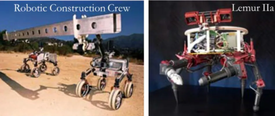
Stroupe (2005) describes how the authors developed two ground systems capable of conducting construction missions. The Robotic Construction Crew and Lemur IIa systems, shown in Figure 9, are, respectively, a two robot ground system for autonomous assembly of structures from large beams and panels, and a construction algorithm testbed for force control for mobility and manipulation and adaptive visual feedback using interchangeable end effectors on six 4DOF limbs. These testbeds, however, are only applicable for captured, ground robotics, and cannot be readily converted to free-flying, action-at-a-distance servicing or assembly satellites. Accordingly, testbeds like these have limited risk reduction potential for on-orbit RSA architectures.
25
Figure 9: Robotic Construction Crew and Lemur IIa (Stroupe, 2005)
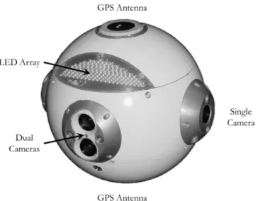
The Fredrickson (2003) paper describes the Mini AERCam, a 10 pound, 7.5 inch diameter free flying nano-satellite aimed at reducing the size of free flyers while maintaining controllability, reliability, and utility as a remote camera platform. The testbed was a technology demonstration unit with the goal of demonstrating the free flyer technologies of relative navigation, stationkeeping, and point-to-point maneuvering. This testbed was successful in its goals, but was unable to be expanded to test additional RSA technologies because of its design. Additionally, its development was focused on a “one step from fight” approach, rather than a multi-step risk reduction sequence of both ground and flight testing, increasing the risk associated with the mission. Additionally, only a single vehicle was created, so testing multi-satellite architectures is much more difficult with the Mini AERCam than with other testbeds which are inherently designed to test multi-satellite configurations. Further discussion of multi-satellite testbeds may be found in Section 3.2.
26
Figure 10: Mini AERCam External View (Fredrickson, 2003)
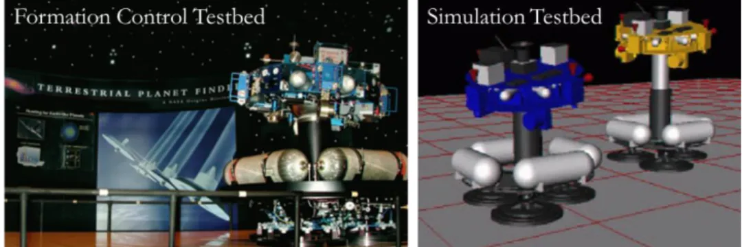
A ground-only testbed has been described in Sohl, 2005. This paper details the complimentary testbeds: the Formation Control Testbed (FCT) and the Formation Algorithms Simulation Testbed (FAST), shown in Figure 11. FCT is a 6DOF testbed that operates on a flat floor. A flight computer, compressed air thrusters, reaction wheels, gyroscopes, and a star tracker are mounted onto an air carriage which uses compressed air to life the structure off the floor and operate on the nearly frictionless surface provided by the expelled compressed air. This hardware testbed operates in conjunction with the FAST simulation testbed, which enables real time tracking and simulation of what occurs on the hardware. This joint testing process merges the use of simulation and hardware-in-the-loop demonstrations to determine the effect of formation algorithms among the three ground robot systems. Unfortunately, the algorithms cannot be tested using these robots beyond the confines of the flat floor, since the robots cannot move without the assistance of the nearly frictionless surface. Additionally, the robots do not have free flying counterparts for testing in reduced gravity aircraft or microgravity facilities like the International Space Station. Nevertheless, the ability for the simulation to verify the hardware testing is an important testbed capability for ensuring model-data correlation.
27
Figure 11: Formation Control Testbed and Formation Algorithms Simulation Testbed (Sohl, 2005) Barnhart has also conducted research with ground hardware to demonstrate a few initial technologies related to the docking of satlets to already orbiting structures with application traceability to the Phoenix mission (Barnhart, 2009). Using a ground facility akin to that of the MIT Flat Floor, Barnhart was able to conduct demonstrations of satlet to floating beam docking with the test setup shown in Figure 12. As shown in the figure, two satlet-like ground units are able to dock to a floating beam. Importantly, however, the demonstrations by Barnhart do not address a significant number of formative stage technologies, and the algorithms that are developed on his ground-only testbed have no further risk reduction steps planned, including on orbit testing aboard the ISS. Therefore, further research is required to continue reducing the risks associated with his demonstrations by conducting testing on orbit in a relevant space environment. As a result, although Barnhart developed the Phoenix concept, he has not yet created an effective risk reduction process.
Figure 12: Ground Floating Beam Docking Demonstration (Barnhart, 2009)
The Synchronized Position Hold Engage and Reorient Experimental Satellites (SPHERES) facility combines many of the testbed capabilities discussed thus far. As described in Saenz-Otero (2000), Saenz-Otero (2005), Mohan (2007), and Mohan (2010), the MIT SPHERES facility affords long duration microgravity testing in a risk tolerant
28
environment aboard the International Space Station, as well as ground testing capabilities with identical hardware and software between both environments. Consequently, testing of many RSA technologies can occur with this facility in the relevant operational environment of microgravity after being demonstrated successfully on the ground. This risk reduction pathway was initially developed in Saenz-Otero (2005), where the author described seven testbed design principles:
1. Iterative Research 2. Enabling a Field of Study 3. Optimized Utilization 4. Focused Modularity
5. Remote Operation and Usability 6. Incremental Technology Maturation 7. Requirements Balance
Here, the first and sixth principles are bolded because they will be further described in Section 2.4. These two design principles played a crucial role in the design and implementation of the risk reduction RSA testbed discussed in this thesis. Further explanation of these two principles can be found in Cockburn (2008) and Larman (2003). The other five, however, while not as immediately prominent in the research, nevertheless played a guiding role as well. For example, the principle of Optimized Utilization can be seen in the discussion of leveraging existing infrastructures where possible and beneficial in Section 2.3. The iterative and incremental research conducted with the SPHERES facility, however, focuses on controls and algorithm development, rather than on specific application to RSA testbeds. Therefore, research is required to develop scaling laws to be able to reduce RSA mission risks.
Scaling laws must be applied both to determine the proper size of a testbed, but also to then scale the results from the testbed back to the flight configuration. Scaling therefore must be incorporated into the developmental process early in order to make the most traceable testbed possible, but also throughout the testing process to ensure that the results that are obtained are capable of reducing the final flight system risks. David (1982) and Schuring (1977) have provided a basis for the creation of scale models. These models are used for sub-scale testing, meaning that the testbeds are a fraction of the size of the final
29
flight system. This reduction in scale is common, since the size of most satellite systems is prohibitively large for full system testing to be cost effective. There are many ways for the testbeds to be created, though there are several common features of each that play a key role in the scale of each testbed.
One of the principal methods for scaling is determining a series of nondimensional parameters, i.e. those parameters which are invariant regardless of the scale of the testbed which they describe. Nondimensional analysis was one of the key research areas for Edgar Buckingham, who described the Principle of Similitude (Buckingham, 1915) and the Buckingham Pi Theorem (Buckingham, 1914). Baker (1991), showed how to apply these concepts to scale models. Kunes (2012) and Sonin (2011) provided valuable insights into various Buckingham Pi numbers, their physical meaning, and their derivations. These fundamental principles of scaling are crucial in comparing results across testbeds of multiple scales, since the nondimensionality of these Buckingham Pi numbers affords the ability to create metrics for determining the extent of traceability from one testbed to another. Further discussion of Buckingham’s work and the scaling of testbed results are in Section 5.1.
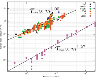
The process of determining scaling laws does not need to be rooted in the creation of nondimensional numbers. Dermitzakis, for example, wrote in his 2011 paper about the process for analyzing existing servo motors to generate a scaling law based for the output torque based on the mass of the motor, a pair of performance characteristics frequently used in determining which motor to select for robotics applications. Figure 13 is a plot of how specific physical parameters can be used to develop equations which can show how changing one physical parameter can affect another.
30
Figure 13: Motor Scaling Law Based on Output Torque (Dermitzakis, 2011)
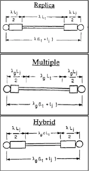
The creation of a scaled testbed affects the physical parameters of the system in comparison to the full scale flight system. Analytical models can only provide an initial predictive analysis of structural properties, while hardware-in-the-loop testing can provide more insight into the behavior and control-structures interactions that will be seen on orbit. There are several means for ground testing hardware to provide data for full scale risk reduction, including full scale component testing, Multiple Boundary Condition Testing (MBCT) of full scale elements (Wada, 1986), or a hybrid modeling approach. Crawley (1988), Gronet (1989), and Crawley (1990) provide detailed analysis of the hybrid scale dynamic modeling technique. Because physical testing does not require analytic expressions for scaling principal and interaction effects, physical tests can often provide better risk reduction capabilities.
As described in these three hybrid modeling papers, the process of hybrid scaling is effectively an extension of simpler scaling methods. Replica scaling centers on the creation of a single scale factor based on the overall size of the testbed or model which is used at various powers to scale all dimensions, physical properties, and system responses. The top block of Figure 14 shows how a replica scale model compares to a full scale system with the added scaling parameter . An extension of the replica modeling technique is the multiple scale modeling technique, where testbeds and models are created with more than one scale factor. An example provided in Gronet (1989) is a model that is built at a scale factor , but is designed to have the response properties of a model built at scale factor .
31
Multiple scale models therefore afford the ability to have physical models built at certain limiting sized, but with the properties of a model which can better reproduce full scale effects. The middle block of Figure 14 shows how a multiply scaled model compares to a full scale system. Hybrid modeling attempts to combine these positive attributes of both of these methods.
Hybrid scaling results in a model or testbed which has the dynamic properties of a model at scale , but with the size governed by the scale factor . Importantly, hybrid scaling introduces what Gronet calls a strut length distortion factor c, which should be kept near unity to minimize the magnitude of compromises in model fidelity. To do so, Gronet recommends using values that are smaller, but close to the values. Following this recommendation allows the principal dynamics of interest to be preserved through scaling and the use of similarity laws. The bottom block of Figure 14 shows how a hybrid model compares to a full scale system. These methods are ways to create a scaled version of final flight hardware, and can then be used to determine the dynamics of the flight system based on scaled testing results. These methods are not specific to RSA missions, though this thesis will study the application of hybrid modeling in particular to reducing RSA technological risks.
32
Figure 14: Replica, Multiple, and Hybrid Scaling Geometry (Gronet, 1989)
The Orbital Express mission is one of only a very small number of servicing missions which has been able to validate several enabling RSA technologies through an on-orbit demonstration between multiple satellites. Shoemaker (2003) provides an overview of the mission, which aimed at testing on-orbit refueling and reconfiguration between two satellites. The Orbital Express mission demonstrated in Low Earth Orbit (LEO) the ability for a servicing satellite named Autonomous Space Transport Robotic Operations (ASTRO) to rendezvous with a satellite named Next Generation Satellite and Commodities Spacecraft (NEXTSat) in order to perform local stationkeeping, docking, hydrazine refueling, and the replacement of an Orbital Replacement Unit (ORU). For this mission, the ORU consisted of a battery module for the NEXTSat power system. Figure 15 shows a diagram of the Orbital Express mission concept of operations. The mission therefore was
33
able to demonstrate many of the technologies that are required for RSA missions, but only two satellites were involved in the demonstration. Multi-satellite aggregations like those in Phoenix were not included, nor were the satellites capable of being reconfigured to test new software based on the results from the initial demonstration. Therefore, additional testing with a new space system is required.
Figure 15: Orbital Express Mission Concept of Operations Diagram (Shoemaker, 2003)
Based on this literature review, it is evident that there is a gap in the current research. There exists a need for a traceable and scalable, low cost testbed capable of operating in an authentic operational environment for the risk reduction of RSA technologies. This testbed will need to be functional both on the ground and in a microgravity environment to enable multiple incremental and iterative testing opportunities and upgradeability overt time. The testbed must therefore be mission flexible while still remaining cost effective. Consequently, this thesis describes the process for creating this new testbed as well as the results of initial testing for the DARPA Phoenix mission.
1.4 Thesis Research Questions
Based on the literature review and research gap presented in Section 1.3, this thesis aims to address the question of:
How can we reduce the risks associated with formative RSA technologies by creating an integrated on-ground and on-orbit testing facility and test sequence?
34
This research question addresses the need to reduce the risks that are inherently associated with on-orbit operations of multi-satellite architectures as well as those associated specifically with on-orbit servicing and assembly. As there is no current methodology for conducting such testing, the thesis poses the hypothesis that:
An incremental, iterative testbed for operation in an authentic environment that leverages existing infrastructure while maintaining traceability to the final RSA project will provide highly valuable risk reduction for formative RSA technologies.
This hypothesis uses the initial research question as a launching point. By directing the hypothesis statement towards the research gap presented earlier in this chapter the hypothesis lays the framework for the research to be conducted and presented in this thesis. Therefore, the hypothesis that the proposed incremental, iterative testbed can reduce RSA risks is evaluated over the course of this work. The research goal, therefore, is:
– To: Provide risk reduction capabilities for future Robotic Servicing and Assembly (RSA) projects
– By: Creating a sequence of incremental, iterative testbeds
– Using: Existing infrastructure in an authentic, yet risk tolerant environment
– While: Maximizing traceability to an on-orbit RSA program 1.5 Thesis Roadmap
Figure 16 presents a graphical description of the flow of this thesis, summarizing the primary steps involved in both the development and use of a risk-reduction testbed for RSA missions, as well as how the thesis chapters map to the testbed development process. Importantly, the right justified white wording presents the high-level overview of what the left justified black wording describes on a chapter-by-chapter basis.
35
Figure 16: Thesis Roadmap
Chapter 1 presents the introduction to the thesis, including the motivation, objective, and literature review with an associated gap analysis. This chapter shows the need for the research presented in this thesis and the background required for introducing the newly developed RSA testing facility.
Chapters 2 and 3 together describe how the testing facility was developed, starting with Chapter 2’s explanation of the requirements that are levied on such a facility, and ending with Chapter 3’s explanation of how to either create or modify a testbed upon which to base the new RSA facility. These two chapters therefore constitute the hardware development stage of the research, where new hardware is designed and manufactured in order to complete risk reduction testing.
Chapters 4 and 5 together describe how to use the facility to both collect and analyze the results that are obtained over the course of testing. Chapter 4 focuses on the need to define a testing sequence clearly that reduces the most risk for the least cost, maximizing the utility and efficiency of all testing, while Chapter 5 focuses on the scaling of the results obtained from the test sequence. The scaling of results is an integral part of the testing process, and is presented here as a means to identify if the testbed can be used as a risk-reduction step based on the testbed properties and how to use the small-scale facility to reduce full-scale risks for the RSA mission.
36
Chapter 6 presents the conclusions that can be gained from this research by summarizing how the facility is capable of reducing full-scale risks associated with formative stage RSA technologies by creating a new, small-scale testbed and an appropriately defined testing sequence with testbed-specific scalability laws in order to fulfill the objectives of this thesis and show the testbed that is developed confirms the stated hypothesis.
37
2
Chapter 2 - Determine RSA Testbed Requirements
2.1 Summary of Requirement Definition Process
Wertz (2011) provides a reference for the requirement definition process by stating that critical features of system or subsystem requirements: should be based on the mission objectives and incorporate a logical flow from system to subsystem requirements, should be incorporated into the trade analysis process to determine the final performance figures for the system, should state the function instead of the form of a given element, and should provide specific quantization of each function to be performed. These critical features apply to every requirement definition process, though the application to risk-reduction testbeds for RSA missions naturally entails a degree of specialization to fit the needs of the new testbed. This section is included to provide a basis against which to compare the types of requirements specific to the testbed presented in this thesis. Additionally, the overview provides background information on the entire process and the fundamentals of proper requirements themselves.
The requirement definition process translates stakeholder needs and wants into quantifiable sets of statements called requirements. These requirements must generally be specific to the particular system/subsystem/component for which they are written, quantifiable/measureable, attainable in the given timeframe of the project, relevant to the overall project, and time bound. Requirements should be written in a top-down manner, typically with several levels in a parent-child arrangement. Upper level requirements describe system elements, while lower level requirements often are more numerically detailed to address individual components. These relationships must be maintained throughout the requirements definition process, and each must be verified by a combination of inspection, analysis, testing, demonstration, or comparison to another similar system or component as would best suit each individual requirement.
Requirements should specify the function of a system element, not its form. In order to prevent requirements from directly limiting possible architectural decisions, the particular function or “what needs to be done” should be specified. Should the form, or “how the function is to be carried out”, be specified in the requirement, then large portions of the viable tradespace will be unnecessarily discounted. This factor is critically important when designing new testbeds for risk reduction. Because the flight system will incorporate new
38
technologies which have not previously operated in space, both the system and technology incorporate new designs which must be tested. Should the requirements on testbed development be written in an unintentionally constrictive manner, as would be the case with forms being specified instead of functions, then feasible testbed configurations may not be considered, possibly preventing a low-cost risk reduction step from occurring. Further, because requirements specify the functions of all levels of the system design, the requirements definition process is closely tied to the system cost, schedule, complexity, and associated risks. Requirements are consequently a major driver in system budgets and allocations.
Requirements can fall into several general categories, including functional requirements, performance requirements, and constraints. These three categories describe the “what needs to be done”, “how well a certain function needs to be accomplished”, and “what cannot be traded”, respectively. Importantly, these three categories have several sub-categories, such as those relating to interface and environmental requirements. Regardless of the category, each requirement needs to be verifiable, quantitative, unambiguous, non-conflicting, and without redundancy with other requirements. These categories do not affect the need to complete requirement closure, either. Requirement closure is the need to ensure that if all requirements are satisfied at each requirement subset (all of the children requirements of a given parent requirement), then the parent requirement would also be satisfied. Such requirement closure enables traceability back to where the sub-requirement was derived. This traceability is discussed in the next section in a modified context: traceability of the testbed to the flight system, instead of child to parent requirements.
A formal set of requirements as defined above should be made for each testbed in order to ensure that the testing conducted with each testbed is directly traceable and scalable to the flight hardware and that the results obtained are capable of reducing RSA risks. The next three sections discuss key aspects of any RSA testbed that should be captured in requirements, and detailed requirements for the on-orbit portion of the RSA risk reduction facility can be found in McCarthy’s SM Thesis (2014).
2.2 Testbed Traceability
In order for a testbed to be effective at reducing risks for a particular mission, it must maintain traceability to the final flight system. There are several key areas in which

![Figure 7: Space Harbor Concept [Top], Corresponding Servicing Concept [Bottom] (Horsham, 2010)](https://thumb-eu.123doks.com/thumbv2/123doknet/14733373.573540/23.918.328.634.122.564/figure-space-harbor-concept-corresponding-servicing-concept-horsham.webp)