Development of Kinematic Coupling Preload Guidelines through
Design and Testing of an Adjustable Micromanufacturing Fixture
by
Brandon A. Evans
B.S.E. Mechanical EngineeringUniversity of Michigan, 2012
Submitted to the Department of Mechanical Engineering in Partial Fulfillment of the Requirements for the Degree of
Master of Science in Mechanical Engineering
at the
Massachusetts Institute of Technology
June 2014
© 2014 Brandon A. Evans All rights reserved.
The author hereby grants to MIT and The Charles Stark Draper Laboratory, Inc. permission to reproduce and to distribute publicly paper and electronic copies of this thesis document in whole
or in any part medium now known or hereafter created.
Signature of Author……… Brandon A. Evans Department of Mechanical Engineering May 9, 2014
Certified by……… Martin L. Culpepper Professor of Mechanical Engineering
Thesis Supervisor
Accepted by……...……… David E. Hardt Professor of Mechanical Engineering Graduate Officer
2
3
Development of Kinematic Coupling Preload Guidelines through
Design and Testing of an Adjustable Micromanufacturing Fixture
by
Brandon A. Evans
Submitted to the Department of Mechanical Engineering on May 9, 2014 in Partial Fulfillment of the Requirements for the Degree of Master of Science in
Mechanical Engineering
A
BSTRACT
In the growing field of non-lithographic micromanufacturing, the ability to properly align a workpiece to a machine limits the attainable tolerances in micro-electro-mechanical-systems (MEMS) prototyping. This limit has created the need for a standard adjustable base for implementation into multiple precision machines, allowing for six-axis adjustment and alignment of workpiece stages that are moved between these machines. Such a fixture—a hybrid positioning fixture (HPF)—has been designed, fabricated, and tested. This HPF has demonstrated <50 nm and <1.5 µrad 2σ (95% confidence) static positional repeatability over 1000 separation-engagement cycles and equivalent 2σ (95% confidence) path-following accuracy when used as a dynamic nano-stage. The HPF has also demonstrated adequate stiffness to ensure <50 nm positional accuracy over an adjustment range of ±5 µm and ±100 µrad in response to 2 N normal and lateral forces during micro-milling operations. The HPF is based upon a kinematic coupling concept, and experiments have been completed that show highly repeatability coupling can be obtained by loading the Hertzian kinematic contacts of the HPF past the fully plastic half-groove material limit. This is a novel result that allows for stiffness increases of ~2.5 and load capacity increases of ~15.5 over conventional kinematic couplings, which are typically loaded to the sub-surface elastic limit.
Thesis Supervisor: Martin L. Culpepper
4
5
A
CKNOWLEDGEMENTS
I would like to thank the Charles Stark Draper Laboratory, the Draper Lab Fellow program, and the Draper Laboratory University Research & Development (URAD) program for sponsoring this research and my Draper advisor Dr. Christopher DiBiasio for supporting this work.
I would like to thank Professor Shorya Awtar at the University of Michigan for recommending me for admission to MIT and my current advisor, Professor Martin Culpepper. Marty recruited me into the Precision Compliant Systems Laboratory (PCSL) and has passed along many valuable lessons in precision engineering over the last two years.
I would like to thank the other members of the PCSL laboratory, my friends in the Lab for Manufacturing and Productivity (LMP), and my friends from my home state of Colorado. My friends at MIT have both supported my research and distracted me from research when needed, whereas my Colorado friends have helped to keep me connected to the world outside of MIT engineering.
Finally, I would like to thank my family for showing continued interest in my work, my parents for inspiring me to continue my education, and my grandfather Douglas Mann for inspiring me to enter the field of Mechanical Engineering at an early age.
6
7
C
ONTENTS
ABSTRACT ...3 ACKNOWLEDGEMENTS ...5 CONTENTS ...7 FIGURES ...9 TABLES ... 15 1INTRODUCTION ... 17 1.1 Motivation ... 191.2 Need for Improved Fixturing ... 20
1.3 Adjustable Fixturing ... 21
1.4 Adjustable Kinematic Coupling ... 23
1.5 Thesis Scope ... 26
2HYBRID POSITIONING FIXTURE DESIGN ... 27
2.1 Refinement of Functional Requirements... 28
2.1.1 Expected Micro-Milling Loads ... 29
2.1.2 Microlution 363-S Micro-Milling Machine Envelope ... 29
2.2 Stiffness Matrix ... 32
2.2.1 Finite Element Analysis Confirmation ... 35
2.3 Actuator Selection ... 37
2.3.1 Piezo Constraint ... 37
2.3.2 Piezo Preload ... 40
2.4 Decoupling Piezo Flexure and Vertical Support Flexure... 42
2.4.1 Half-Groove Stiffness ... 43
2.5 Lateral Compliance Flexure ... 45
2.5.1 Limitations ... 49
2.6 Hertzian Contact ... 50
8
2.7 Preload Mechanism ... 53
2.7.1 Limitations of Electromagnet Preload for Dynamic Applications ... 55
2.8 Kinematics ... 57
2.9 Summary ... 58
3FIXTURE TESTING AND RESULTS ... 59
3.1 Stiffness Testing ... 60 3.2 Repeatability Testing ... 63 3.2.1 Temperature Compensation ... 64 3.3 Dynamic Testing ... 67 3.3.1 Path Calibration ... 68 3.4 Cutting Tests ... 76 3.5 Summary ... 77
4KINEMATIC PRELOAD GUIDELINES ... 79
4.1 Kinematic Coupling Failure Modes ... 81
4.1.1 True Brinelling ... 82
4.1.2 False Brinelling and Smearing ... 86
4.1.3 Cone Fracture ... 89
4.2 Testing ... 95
4.2.1 Indentation Testing... 96
4.2.2 Surface Roughness Testing ... 100
4.3 Fatigue ... 103
4.4 Summary ... 106
5CONCLUSION... 107
5.1 Future Work ... 109
9
F
IGURES
Figure 1.1: HPF prototype used to confirm that fine repeatability is attained with fully plastic
Hertzian contact interfaces ... 17
Figure 1.2: Palletized adjustable fixturing being used in a line transfer manufacturing operation [25, p. 71]. © Elsevier. Reproduced with permission. All rights reserved. ... 22
Figure 1.3: Typical ball-groove kinematic coupling [28, p. 277]. © Elsevier. Reproduced with permission. All rights reserved. ... 23
Figure 1.4: Half-groove actuation in a hybrid positioning fixture (HPF) offsets fabrication and assembly error [28, p. 277]. © Elsevier. Reproduced with permission. All rights reserved. ... 24
Figure 1.5: The HPF is capable of both high accuracy and fine repeatability [25, p. 66]. Edited figure. © Elsevier. Reproduced with permission. All rights reserved. ... 24
Figure 1.6 (left): First iteration of the HPF: a) stage and b) base [28, p. 277]. © Elsevier. Reproduced with permission. All rights reserved. ... 25
Figure 1.7 (right): Second iteration of the HPF: a) stage and b) base [32, p. 2]. © ASPE. Reproduced with permission. All rights reserved. ... 25
Figure 2.1: Finished HPF in the Microlution 363-S micro-milling machine ... 27
Figure 2.2: HPF exploded view ... 27
Figure 2.3 (left): Microlution 363-S micro-milling machine orthogonal view ... 30
Figure 2.4 (right): Tool finder assembly limits the space near the top of the chuck ... 30
Figure 2.5 (left): Erowa pallet uses a shank for alignment and flexure plate for preload ... 30
Figure 2.6 (right): HPF is designed for use with Erowa pallet alignment system ... 30
Figure 2.7 (left): Erowa pneumatic chuck used in Microlution 363-S micro-milling machine .... 31
Figure 2.8 (right): HPF engaged in the Microlution 363-S micro-milling machine ... 31
Figure 2.9: Each half-groove stiffness is simplified to three linear springs ... 32
Figure 2.10: Stage coordinate system ... 34
Figure 2.11: Concentrated 2 N force over a 1/8” diameter circle causes local strain ... 35
Figure 2.12 (a-c): FEA analyses of 100 N forces on half-groove assembly: (a) -X, (b) -Y, (c) -Z 35 Figure 2.13 (left): Spherical tip... 38
10
Figure 2.15 (left): Spherical tip with a 0.25 m diameter shows minimal height discretization .... 39
Figure 2.16 (right): Spherical tip with a 1.0 m diameter shows ~750 µm discretization at peak due to milling resolution ... 39
Figure 2.17: HPF half-groove assembly ... 39
Figure 2.18: Preloading piezo assembly generates significant increases in stiffness ... 40
Figure 2.19: Interaction with a linear stiffness reduces the piezo range ... 40
Figure 2.20: Piezo transmission exploded view ... 41
Figure 2.21: Decoupling piezo flexure (DPF) supports loads in the y and z directions ... 42
Figure 2.22: Fixture loads intersect the center of stiffness of the decoupling flexure ... 43
Figure 2.23 (left): Vertical support flexure reduces My moment arm from Z1 to Z2 ... 43
Figure 2.24 (right): Vertical support flexure transfers tangential loads to ground ... 43
Figure 2.25: Decoupling fixture is modeled as a fixed-fixed beam ... 44
Figure 2.26: Lateral compliance flexures reduce surface hysteresis [41, p. 48]. © Elsevier. Reproduced with permission. All rights reserved. ... 45
Figure 2.27 (a-c): Non-planar lateral compliance flexure (LCF) concepts: a) single hinge, b) dual hinge, and c) hourglass ... 45
Figure 2.28: Planar groove flexure used in previous HPF iterations [28, p. 279]. © Elsevier. Reproduced with permission. All rights reserved. ... 46
Figure 2.29: Hourglass flexure exhibits acceptable performance at reasonable aspect ratios ... 47
Figure 2.30: Single hinge flexure exhibits acceptable performance at high aspect ratios ... 47
Figure 2.31: Planar flexure exhibits acceptable performance at high aspect ratios ... 47
Figure 2.32: Removing material only in primary movement directions simplifies fabrication .... 48
Figure 2.33 (left): Lateral compliance flexure resists vertical motion of ball ... 49
Figure 2.34 (right): FEA results predict a reduction in vertical travel with higher lateral half-groove stiffness (deformation scale is exaggerated) ... 49
Figure 2.35 (a, b): Reduction in travel appears as a negative displacement error in opposing half-groove assemblies ... 49
Figure 2.36 (a, b): Attainable Hertzian stiffness and preload increases with ball radius and yield strength as shown in: a) AISI 304 and b) AISI 52100 ... 51
Figure 2.37 (left): Canoe ball contains large radii contacts in a compact envelope ... 52
11
Figure 2.39 (left): Spherical tips manufactured using micro-milling machine ... 52
Figure 2.40 (right): Fully assembled canoe ball in contact with groove ... 52
Figure 2.41: 80% of maximum stiffness is obtained with a 690 N preload ... 53
Figure 2.42 (left): Preload coupling experiences 130 µm of displacement under preload ... 54
Figure 2.43 (right): Electromagnet plate experiences 120 µm of displacement under preload .... 54
Figure 2.44 (left): Preload force is sensitive to gap distance ... 56
Figure 2.45 (right): Moving HPF across its 10 µm range results in significant changes in preload force... 56
Figure 3.1: HPF undergoing z axis stiffness testing ... 60
Figure 3.2 (a, b): HPF exhibits repeatable deformation in response to a 9.8 N force in -Y ... 61
Figure 3.3: All measured stiffness values satisfy requirements, within error, for both: a) the tooling ball HPF stage and b) the canoe ball HPF stage ... 61
Figure 3.4: HPF fixture undergoing repeatability testing... 63
Figure 3.5 (a-f): Fixture position shows a linear relationship to temperature with some apparent oscillation ... 64
Figure 3.6: Thermocouple data follow exponential behavior (R2=0.99) ... 65
Figure 3.7 (a-f): Linear thermal compensation reduces fixture drift ... 65
Figure 3.8 (a-h): Position and temperature data show FFT peaks at similar frequencies ... 66
Figure 3.9 (a-f): Calibrated data show no temperature drift or oscillation... 66
Figure 3.10: HPF path-following demonstration shows <50 nm 2σ path error ... 67
Figure 3.11 (a-f): Post-calibration errors are primarily stochastic ... 67
Figure 3.12: Early path tests showed significant error in stage position and orientation ... 68
Figure 3.13 (a-f): Half-groove displacements demonstrate time-variable errors ... 69
Figure 3.14 (a-f): Proportional half-groove error suggests piezo calibration error ... 69
Figure 3.15 (a-f): Piezo calibration error leads to proportional half-groove error ... 70
Figure 3.16 (a-f): Post-calibration displacement data show no proportional error ... 70
Figure 3.17 (a-f): Adjusting piezo calibration improves HPF performance ... 71
Figure 3.18: Position-dependent error remains after piezo calibration ... 71
Figure 3.19 (a-f): Errors are non-stochastic and show a relation to commanded path ... 72
Figure 3.20: Decoupled path allows for more efficient calibration ... 72
12
Figure 3.22: Half-groove error shows linear relation to sliding distance (no sliding in half-grooves
not shown) ... 73
Figure 3.23 (a-f): Parasitic θx relation plots show linear correlation errors and hysteresis ... 74
Figure 3.24 (left): Data truncation is needed to calculate true parasitic correlation ... 75
Figure 3.25 (right): Phase shifting eliminates following error ... 75
Figure 3.26: Post-calibration half-groove data show only stochastic errors ... 75
Figure 3.27 (left): Top view of plunge cut performed with HPF ... 76
Figure 3.28 (right): Surface topology of plunge cut performed with HPF... 76
Figure 4.1: After shakedown limit is exceeded, unloading changes from: a) perfectly elastic to b) plastic (redrawn from [62]) ... 84
Figure 4.2 (a-f): Fretting damage [69, p. 93]. © Elsevier. Reproduced with permission. All rights reserved. ... 86
Figure 4.3: Smearing along a kinematic coupling groove [28, p. 278]. © Elsevier. Reproduced with permission. All rights reserved. ... 87
Figure 4.4: Tensile stress reaches a maximum at the radius of the Hertzian contact ... 90
Figure 4.5: Cone crack propagation in a brittle specimen subjected to Hertzian pressure [83, p. 981]. © Institute of Physics. Reproduced with permission. All rights reserved... 91
Figure 4.6: Plastic indentation and cone fracture of silicon nitride: a) fine-grain, b) medium-grain, and c) coarse-grain [78, p. 2371]. © John Wiley and Sons. Reproduced with permission. All rights reserved. ... 92
Figure 4.7 (a, b): Under equivalent Hertzian pressure, (a) AISI 52100 Bearing Steel requires larger flaw sizes for fracture compared to (b) silicon nitride ... 93
Figure 4.8: Preload testing apparatus ... 97
Figure 4.9: Decoupling limits on metrology frame ... 97
Figure 4.10 (a-f): Repeatability data for fully elastic contact test show coupling drift ... 98
Figure 4.11 (a-f): Repeatability data for elastic-plastic contact test show lower drift than fully elastic contact test ... 98
Figure 4.12 (a-f): Repeatability data for fully plastic contact test show minimal drift... 98
Figure 4.13: Repeatability improves with preload ... 99
Figure 4.14: Attainable Hertzian stiffness and load capacity increase significantly by loading to the shakedown limit (results shown for steel balls on nickel half-grooves)... 100
13
Figure 4.15: Master surface finish scale with electroformed nickel swatches ... 101 Figure 4.16 (left): Nickel swatches affixed to grooves via adhesive ... 101 Figure 4.17 (right): Polished tooling ball in contact with swatches ... 101 Figure 4.18: Five of six fits have an error >100%, suggesting no significant relationship between surface roughness and repeatability ... 102
14
15
T
ABLES
Table 1.1: Third HPF prototype exhibits improved performance over previous prototypes ... 25
Table 2.1: HPF functional requirements ... 28
Table 2.2: Stiffness FEA results agree with predicted values within 20% ... 36
Table 2.3: P-888.51 piezoelectric actuator specifications [38]... 37
Table 2.4: Stiffness equations for lateral compliance flexure concepts ... 46
Table 2.5: Predicted tooling ball HPF stiffness meets linear requirements ... 51
Table 2.6: Predicted canoe ball HPF stiffness meets requirements in five of six axes ... 52
Table 2.7: Predicted HPF performance ... 58
Table 3.1: Current HPF prototype exhibits improved performance over previous prototypes ... 59
Table 3.2: All predicted linear stiffness values lie within the error range of measured values, while measured rotational stiffness values tend to exceed predicted values ... 62
Table 3.3: Current HPF prototype satisfies five of six repeatability specifications ... 63
Table 3.4: 2σ Error ... 67
Table 4.1: Main considerations in the selection of preload ... 79
Table 4.2: Indentation limits for a ball against a flat in a crystalline material ... 84
Table 4.3: NASA STD-5017 allowable contact stresses [68] ... 85
16
17
C
HAPTER
1
I
NTRODUCTION
The purpose of this thesis is to generate an understanding of the relationship between contact pressure and repeatability for ball-flat Hertzian contacts subjected to high-force cyclic loading. Typically, the allowable design contact pressure in a metallic Hertzian interface with fine repeatability requirements is considered to be the maximum pressure that avoids any sub-surface plastic deformation in the flat surface. The author of this thesis hypothesizes that increasing the operational contact pressure into the fully plastic regime could drastically improve the stiffness and load capacity of a Hertzian contact without sacrificing repeatability. This hypothesis is confirmed in this thesis. In the fully plastic-regime, work-hardening of a Hertzian contact produces a conformal surface through accumulation of plastic strain during an initial wear-in period. This novel selection of the maximum allowable Hertzian pressure is tested using an adjustable kinematic coupling—a hybrid positioning fixture (HPF)—shown in Figure 1.1.
Figure 1.1: HPF prototype used to confirm that fine repeatability is attained with fully plastic Hertzian contact interfaces
The understanding generated in this thesis is important because the current allowable Hertzian contact pressure guidelines limit the attainable stiffness and load capacity in kinematic couplings, which utilize six Hertzian ball-flat contacts. The preload of the HPF is increased such that all six
18
kinematic contacts exceed the fully plastic Hertzian contact limit. Under this high preload, the HPF exhibits repeatability performance that matches or exceeds the repeatability of any kinematic coupling presented in past literature. This result allows future researchers to select kinematic coupling preloads for achieving higher stiffness (×2.5) and higher load capacity (×15.5) compared to traditional kinematic couplings.
These preload guidelines impact the design guidelines for sub-micron repeatability kinematic fixtures used in micromanufacturing operations. There is currently a need for an adjustable standard base for implementation into multiple micromanufacturing machines, allowing for full six-axis adjustment and alignment of workpiece stages that are moved between these machines. The HPF was developed to fulfill this need in the past, but previous HPF iterations have lacked sufficient stiffness for use in contact micromanufacturing operations. The iteration of the HPF created in this thesis achieves high stiffness without sacrificing repeatability, and this HPF device directly benefits from the novel kinematic coupling preload guidelines described here. Under high preload, the HPF exhibits sufficient load capacity and stiffness for implementation into traditional high-force manufacturing operations.
19
1.1 Motivation
In the field of manufacturing, the ability to properly align a workpiece to a machine acts as a limiting factor in the quality of finished parts—something that has only become more pronounced as tolerance ranges and feature sizes have decreased over time. In manufacturing operations that require multiple machines, robotic workpiece transfer, and CNC machining, workpiece positioning may limit attainable tolerances, creating a need for expensive high-accuracy fixtures [1]. Over the last few decades, many manufacturing operations have begun to take advantage of kinematic design principles to develop exact constraint fixtures [2]. The absence of forced geometric conformity in these exact constraint fixtures reduces potential error sources caused by large contact areas, resulting in finer repeatability. Reducing the area of contact between a fixture and a workpiece results in Hertzian contacts that exhibit higher contact pressures than traditional fixtures, making kinematic fixtures more vulnerable to local deformation. As fixtures deform, the resulting overconstraint decreases the kinematic nature of the fixture and potentially affects workpiece positioning. Currently, there is a lack of understanding of the interaction between high contact pressures and kinematic coupling repeatability. The research presented in this thesis has been completed in the interest of understanding the relationship between preload, plastic surface deformation, and material failure for Hertzian contacts subjected to high-force cyclic loading. This contact mechanics knowledge may be used to select optimal preloads for maximizing the repeatability of kinematic couplings. In addition, a new type of adjustable kinematic coupling has been created in an effort to further improve the errors intrinsic to kinematic fixtures.
20
1.2 Need for Improved Fixturing
Over the last few decades, improvements in manufacturing capabilities have resulted in a large amount of research and development of micro-electro-mechanical systems (MEMS). The market for MEMS devices is estimated to reach $20B by 2016, with applications in the fields of microfluidics (24%), inertial measurement devices (24%), pressure sensors (13%), inkjet heads (10%), and optical components (10%) [3]. Bosch has suggested that cell phones, smart homes, smart phones, and personal medical diagnostics will allow humans to interact with ~1000 MEMS devices on a semi-daily basis by 2017 [3]. Due in part to this market, innovation in the field of micromanufacturing has been highly encouraged by experts [1]. Typically, MEMS devices are prototyped through a lithography or micro-molding operation that involves a tooling process, four or more weeks, and an investment of ten to forty thousand dollars [4]. These time and monetary costs delay the prototyping of devices, slowing R&D. However, the increasing availability of electrical-discharge machining (µ-EDM), milling (µ-milling), and micro-stereolithography (µ-SLA) machines has introduced the ability to produce three-dimensional parts with engineering materials in matters of hours/days rather than weeks. Although µ-EDM is limited to vertical, horizontal and slanted surfaces, structural features as small at 0.5 µm have been produced using this method [1]. Micro-milling is able to produce fully three-dimensional features to an accuracy of 2 µm with cutting tools as small as 5 µm [5], and μ-SLA rapid prototyping has produced accurate machine parts as small as 15 µm [1]. MEMS devices generally do not contain sub-micron feature sizes, so micron-level tolerance ranges would be appropriate for prototyping either true-size or scaled versions of these devices. There are also meso-scale devices that require micron tolerances. For instance, in precision compliant systems that implement flexure beams, device stiffness is sensitive to micron errors in beam thickness [6]. Although the machines mentioned above are capable of achieving necessary feature accuracy in a single operation, the relative positional accuracy of features is compromised if the parts need to be moved between machines or removed for in-process inspections. There is a need for the development of a fixture that offers actuation relative a machine’s inherent actuation to align the coordinate systems of workpieces and machines. This type of active fixturing has been researched in recent years, as is presented in the next section.
21
1.3 Adjustable Fixturing
Fixturing is an important aspect of all manufacturing operations, and, if not properly regulated, may reduce or eliminate the benefits gained by CNC machinery and automated workpiece transfer systems. Fixtures are responsible for accurately aligning a workpiece reference frame to the reference frames of multiple machines with fine repeatability. A fixture must also maintain the position of a workpiece in the presence of dynamic machining forces without deforming or damaging the piece. Although traditional fixturing operations have been largely dependent on an operator’s experience to ensure that a workpiece is correctly positioned and secured, there has been a resent push towards active fixturing that provides feedback and even actively adjusts for any potential workpiece positional errors during a manufacturing operation. Some of the first fixture metrology was investigated when Gupta et al. [7] incorporated dynamometers into a V-block fixture to measure clamping and machining forces and identify safe clamping regimes. Since then, there has been other research to determine the effect of clamping and machining force on workpiece position through eddy current displacement sensors [8], vision systems [9], and MEMS transducers [10]. There has also been research related to the introduction of actuation into fixtures. Tuffentsammer first incorporated eccentric rollers into a fixture that could be rotated to account for different workpiece geometries in 1981 [11]. Since then, there has been a move toward fixturing that positions, manipulates, and secures workpieces that would be difficult to secure in a traditional clamp, such as the grippers presented in [12] and the multi-finger modules presented in [13],[14],[15],[16], and [17]. Some of the most popular research in recent years has been the introduction of fixtures based upon parallel kinematic mechanisms (PMKs) [18][19][20][21]. These systems have shown higher positional repeatability and stiffness compared to Cartesian systems, making them ideal for use in machining centers [19][22]. The combination of metrology and actuation has led to many of these fixtures being used as closed loop systems that apply optimal clamping forces and select optimal orientations during machining operations. A thorough review of these active fixtures is presented in [23].
Although there have been many developments in the areas of active fixturing, the complexity and form factors of many of these technologies requires custom machining centers to be built to interact with them. The complexity and reconfigurability of these systems makes them valuable for
low-22
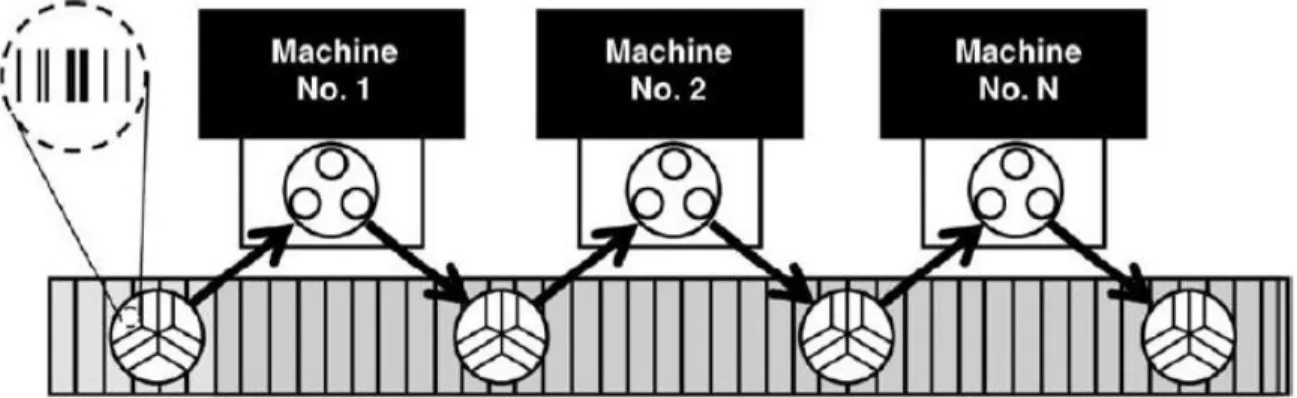
volume high-variety contract machine shops, but is excessive for most in-house prototyping operations. Many modern day fixturing operations do not require complete orientation control, and would see higher benefit from an elegant high-stiffness fixture that provides slight orientation and positioning adjustment to account for typical stochastic manufacturing and fixturing errors. This type of “super-resolution” in a micromanufacturing machine was recently demonstrated by Balasubramanian [24], when a nano-stage was adapted for use on a micro-mill and electrochemical deposition machine. This allowed for an order of magnitude increase in the positional accuracy of these machines, but this stage could only be adjusted in-plane and could not be aligned between machines with fine repeatability. There is a need for an adjustable standard base for implementation in multiple precision machines, allowing for full six-axis adjustment and alignment of workpiece stages that are moved between machines. This type of fixture would allow for rapid machine alignment as workpieces are moved through different process stations, perhaps through a fixture-affixed RFID tag containing calibration information (Figure 1.2).
Figure 1.2: Palletized adjustable fixturing being used in a line transfer manufacturing operation [25, p. 71]. © Elsevier. Reproduced with permission. All rights reserved.
In contrast to the majority of adjustable fixtures presented in literature, which depend on elastic averaging in conjunction with feedback systems to achieve fine repeatability, a fixture that exhibits exact constraint achieves fine repeatability with lower complexity. Exact constraint fixtures such as kinematic couplings are promising candidates to address the fixturing needs in the field of MEMS prototyping. An overview of a new type of adjustable kinematic couplings is presented in the following section.
23
1.4 Adjustable Kinematic Coupling
Kinematic couplings (KCs) are positioning fixtures that operate on the principle of exact constraint. By constraining an object with exactly six contact vectors in the proper directions, an object may be constrained without any redundancy, preventing any deformation in the object. A typical kinematic coupling is presented in Figure 1.3. There has been a great deal of KC research in recent decades, and a through overview of this literature up to 2010 is presented in [26]. Kinematic coupling applications are currently being developed for semiconductor wafer positioning by Intel and Teradyne and robotics positioning by ABB Group and Ford [26][27].
Figure 1.3: Typical ball-groove kinematic coupling [28, p. 277]. © Elsevier. Reproduced with permission. All rights reserved.
A traditional passive kinematic coupling provides a much higher degree of repeatability compared to traditional overconstrained fixtures (such as pin-hole fixtures), but is subject to similar accuracy limitations. Since the positioning and orientation of a KC stage is dependent on the geometric fidelity of the base, groove surfaces, and balls, traditional kinematic couplings provide accuracy up to the manufacturing tolerances of these components. By incorporating actuation into the individual half-grooves to eliminate any fabrication and assembly error, a high degree of both accuracy and repeatability is achieved. This concept is referred to as a hybrid positioning fixture (HPF) in this document, and is demonstrated graphically in Figure 1.4 and Figure 1.5. This HPF concept was originally presented by Varadarajan and Culpepper [28]. Past researchers have attempted to introduce precise adjustment into kinematic couplings through eccentric balls [25], adjustment of a high preload [29], and linear actuation of the balls [30], but linear actuation of individual half grooves has resulted in the highest accuracy and repeatability for adjustable kinematic couplings to date [28][31][32].
24
Figure 1.4: Half-groove actuation in a hybrid positioning fixture (HPF) offsets fabrication and assembly error [28, p. 277]. © Elsevier.
Reproduced with permission. All rights reserved.
Figure 1.5: The HPF is capable of both high accuracy and fine repeatability [25, p. 66]. Edited figure. © Elsevier. Reproduced with permission. All rights reserved.
The incorporation of linear actuators directly into the half-grooves of the HPF results in a tight structural loop, producing a highly stiff fixture in a small envelope. This approach allows for fine adjustment of the six half-groove positions which can be used to eliminate the fabrication/assembly errors associated with both the HPF and the surface to which the HPF is mounted. The HPF allows for multiple stages—each with their own inherent error—to be used on multiple HPF bases with high accuracy after calibration. The HPF can also adjust for time-variable fixture errors such as wear. Varadarajan and Culpepper created two HPF iterations (Figure 1.6 and Figure 1.7) that exhibited the performance specifications (limited data available) shown in Table 1.1 [28][31][32].
25
The repeatability values shown are the 2σ values taken over 1000 sequential couplings of the fixtures. The second prototype was developed to fit within the envelope of the Microlution 363-S micro-milling machine, but with no means to attach to the machine.
(a) (b) (a) (b)
Figure 1.6 (left): First iteration of the HPF: a) stage and b) base [28, p. 277]. © Elsevier. Reproduced with permission. All rights reserved.
Figure 1.7 (right): Second iteration of the HPF: a) stage and b) base [32, p. 2]. © ASPE. Reproduced with permission. All rights reserved.
Table 1.1: Third HPF prototype exhibits improved performance over previous prototypes
X Y Z θx θy θz Iteration 1 Range (µm or µrad) 50 56 88 960 1100 550 2σ Repeatability (µm or µrad) 116 174 576 2.8 2.0 4.6 Stiffness (N/µm) 7.1 7.1 7.3 – – – Iteration 2 Range (µm or µrad) 3 3 3 – – – 2σ Repeatability (µm or µrad) 193 128 111 14.0 20.0 2.7 Stiffness (N/µm) – – – – – – Iteration 3 Range (µm or µrad) 10 10 10 200 200 200 2σ Repeatability (µm or µrad) 39 37 46 1.0 1.4 0.4 Stiffness (N/µm) 35.5 40 58.20 0.051 0.059 0.093
The main limitation of these first two prototypes was low stiffness, making them unsuitable for most contact manufacturing operations. A third prototype has therefore been designed, fabricated, and tested as part of this thesis (Figure 1.1). This prototype was built specifically for the Microlution 363-S micro-milling machine, and has showed an order of magnitude stiffness improvement over earlier devices. In addition, this design matches or exceeds the repeatability of both past devices, as shown in Table 1.1.
26
1.5 Thesis Scope
This remainder of this thesis is presented in four chapters. Throughout these chapters, all mention of the hybrid positioning fixture (HPF) will refer to the third iteration of the fixture unless otherwise noted. In chapter two, the HPF design process is presented. This includes the determination of functional requirements, derivation of analytical design tools, and presentation of the completed prototype. In chapter three, the testing and performance of the HPF is presented. This testing includes stiffness, repeatability, and dynamic path accuracy experiments. In chapter 4, the current state understanding of kinematic coupling preload is presented, and failure modes of kinematic couplings are discussed. Once an understanding of kinematic coupling preload theory is established, experimental results are presented that introduce novel kinematic coupling preload guidelines. The thesis ends with a research conclusion in chapter five.
27
C
HAPTER
2
H
YBRID
P
OSITIONING
F
IXTURE
D
ESIGN
This chapter presents the methodology and analysis used to design the third iteration of the hybrid positioning fixture (HPF). A photo of the completed fixture in the Microlution 363-S micro-milling machine and an exploded CAD view of the design are presented in Figure 2.1 and Figure 2.2, respectively.
Figure 2.1: Finished HPF in the Microlution 363-S micro-milling machine
28
2.1 Refinement of Functional Requirements
The goal of this project was to build a fixture that would achieve 50 nm positional accuracy and 10 µm single-axis (x, y, and z) adjustability in the position of a detachable stage to be used in the Microlution 363-S micro-milling machine. It was necessary to refine the project functional requirements into design parameters to begin analyzing potential concepts. Rotational and positional errors were predicted to be independent stochastic variables in this application. Although error stack up was expected to occur because of these combined effects, rotational errors are dependent on position, and an equal amount of error stack-up and error reduction was expected to occur across the symmetric stage area. Accordingly, error sources were addressed individually, with the goal of setting the average coupling positional accuracy at 50 nm over the area of the stage. The accuracy requirement involves workpieces being removed from and replaced into the Microlution machine with less than 50 nm deviation from a desired calibrated position. Since calibration is expected to be completed using metrological feedback and actuators with sub-nanometer resolution are planned for use in the HPF (see section 2.3), the positional accuracy of the kinematic coupling is primarily dependent on the coupling repeatability. The repeatability requirement was therefore set at 50 nm. The work area of the Microlution 363-S micro-milling machine is 63 mm × 63 mm [5], so the angular misalignment about the center of the stage was set at ±1.1 µrad to prevent a 50 nm error at the stage corner. The use of flood cooling in a micro-milling environment can be used to ensure thermal stability of the HPF and requires the HPF to be compatible with flood coolant. The stiffness requirement for the fixture was calculated from the expected operational loads, as presented in the following section. The functional requirements are presented in Table 2.1.
Table 2.1: HPF functional requirements
Linear Repeatability (nm) 50
Rotational Repeatability (µrad) 1.1
Single Axis Travel (X, Y, Z) (µm) 10
Linear Stiffness (N/µm) 40
Rotational Stiffness (N-m/µrad) 0.04
29
2.1.1 Expected Micro-Milling Loads
It was necessary to estimate the loads that the fixture would experience in operation to determine the required stiffness of the HPF. There has been a significant amount of research in the area of micro-scale cutting mechanics because of complex interactions such as ploughing that occur in micro-scale chips [33], but a conservative order of magnitude estimate was adequate for the purposes of HPF design. Equation (2.1) was introduced in [34] using the models created in [35] and [36] for the purpose of predicting micro-milling forces (ft – chip load [µm/tooth], baxial – axial
depth of cut [m]) related to 6061 aluminum. These forces may be scaled by the shear strength of the workpiece (τyworkpiece) being machined. The ratio of normal force to feed force is approximately
0.6-0.8 [34].
𝐹𝑐 ≈ (𝜏𝑦𝑤𝑜𝑟𝑘𝑝𝑖𝑒𝑐𝑒
𝜏𝑦6061 ) 50.47 ∙ (𝑓𝑡∙ 𝑏𝑎𝑥𝑖𝑎𝑙)
.445 (2.1)
Maximum cutting forces are generated when using a large diameter end mill at a heavy chip load. Assuming standard cut depths and chip loads [6] with a 1/8” end mill (largest available for Microlution machine) cutting standard 304 stainless steel, forces as high as 5 N are expected. However, during precision work with tools <0.5 mm in diameter, expected cutting forces are 2 N or lower. The fixture stiffness requirement was, therefore, set at 40 N/µm stiffness laterally and axially to maintain the 50 nm accuracy target. The fixture stiffness requirement was set at ~0.04 N-m/µm in every rotational orientation to hold 50 nm accuracy in all axes during milling near the edge of the stage. If using smaller end-mills, the required stiffness drops by up to two orders of magnitude [24][37], but the functional requirements were chosen for more aggressive cutting scenarios.
2.1.2 Microlution 363-S Micro-Milling Machine Envelope
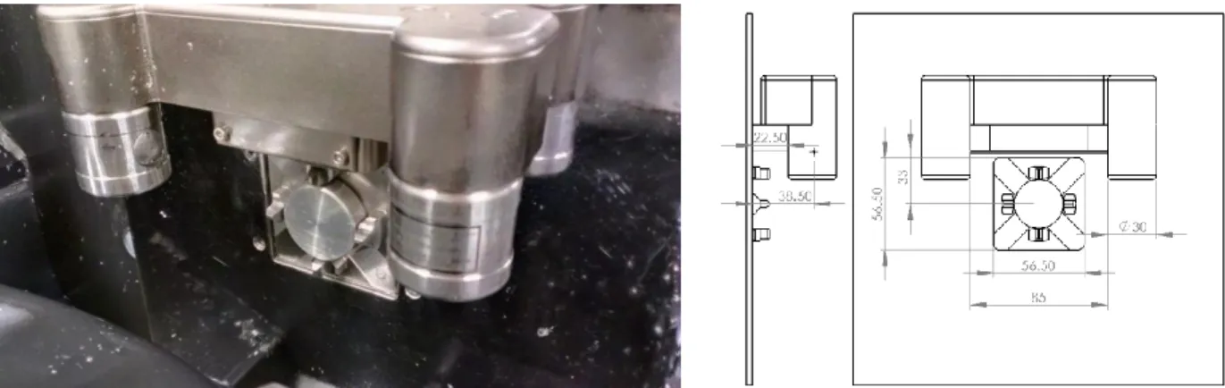
The development of this stage for integration with the Microlution 363-S micro-milling machine defined a device envelope (Figure 2.3 and Figure 2.4). This presented a challenge, because the tool finding apparatus limits space near the top of the pneumatic chuck. Significant effort was made in selecting components and setting dimensions imposed by this limited envelope.
30
Figure 2.3 (left): Microlution 363-S micro-milling machine orthogonal view Figure 2.4 (right): Tool finder assembly limits the space near the top of the chuck
It was decided that for easy integration with the Microlution machine, the HPF needed to secure using the same Erowa shank and preloading apparatus as the current Microlution pallets (Figure 2.5, Figure 2.6, and Figure 2.7). This Erowa alignment system is used with µ-EDM machines along with precision lathes, allowing the HPF to easily integrate with multiple machines. The current Erowa pallet on the Microlution machine has been shown to obtain repeatability of 240 nm in z, 1.70 µrad in θx, and 2.3 µrad in θy [6], but cannot be adjusted. The HPF is shown engaged in the
micro-mill in Figure 2.8.
Figure 2.5 (left): Erowa pallet uses a shank for alignment and flexure plate for preload Figure 2.6 (right): HPF is designed for use with Erowa pallet alignment system
31
Figure 2.7 (left): Erowa pneumatic chuck used in Microlution 363-S micro-milling machine Figure 2.8 (right): HPF engaged in the Microlution 363-S micro-milling machine
32
2.2 Stiffness Matrix
A generalized parameter-based stiffness model was developed early in the design process to compare the performance of different concepts. This section presents the method by which this matrix was developed. The basic concept for each half-groove was an actuator in series with a groove flexure (discussed in section 2.5) and a Hertzian contact point (discussed in section 2.6) at which the ball contacts the half-groove surface. All of these elements were modeled as linear and rotational springs, which were further reduced to three total springs (x, y, and z) as shown in Figure 2.9. All rotational and linear loads applied to the stage are supported through a combination of normal and tangential forces at each of the six kinematic contacts.
Figure 2.9: Each half-groove stiffness is simplified to three linear springs
The first step in obtaining the system stiffness matrix was rotating the actuator stiffness matrix (coordinate system CSA) such that they aligned with the groove flexure and Hertzian stiffness
matrices (coordinate system CSHG), as shown in (2.2) through (2.7). In all equations below, uQ is
a displacement vector defined in coordinate system Q, fQ is a force vector defined in coordinate
system Q, 𝑅𝑄𝑊 is a rotation matrix necessary to convert vectors defined in coordinate system Q to
coordinate system W. The actuator, half-groove, and ball coordinate systems are scripted by A, HG, and B, respectively. The stiffness matrices of the actuator, groove flexure, and Hertzian contact are scripted by ACT, GF, and H, respectively. The matrix math was simplified by assuming that 𝐾𝐴𝐴, 𝐾
𝐺𝐹𝐻𝐺, and 𝐾𝐻𝐻𝐺 had no rotational components. Only normal and tangential loads are
applied at the Hertzian contact, so the only applied moments in the chain would result from the separation L between the actuator and the tangential loads applied at the Hertzian contact (Figure 2.9). A rotational stiffness matrix 𝐾𝐴𝐶𝑇𝐵 𝑅𝑂𝑇 was constructed and added in series with the linear matrices as shown in (2.10) through (2.14). The total stiffness of the half-groove, defined in the
33
coordinate system of the ball (𝐾𝐻𝑎𝐺𝑟𝐵 ), was determined using (2.8), (2.9), and (2.14). No moments
are applied at the Hertzian contacts so 𝐾𝐻𝑎𝐺𝑟𝐵 is a 3×3 translational stiffness matrix.
𝑢𝐻𝐺 = 𝑅𝐴𝐻𝐺𝑢𝐴 (2.2) 𝑅𝐴𝐻𝐺 = [ sin (𝛼)0 0 cos (𝛼)1 0 −cos (𝛼) 0 sin (𝛼)] (2.3) 𝑓𝐴 = 𝐾𝐴𝐶𝑇𝐴 𝑢 𝐴 (2.4) 𝑓𝐴 = 𝑅𝐻𝐺𝐴 𝑓𝐻𝐺, 𝑤ℎ𝑒𝑟𝑒 𝑅𝐻𝐺𝐴 = 𝑅𝐴𝐻𝐺 −1 (2.5) 𝑓𝐻𝐺 = 𝑅𝐻𝐺𝐴 𝑇𝐾 𝐴𝐶𝑇𝐴 𝑅𝐻𝐺𝐴 𝑢𝐻𝐺 (2.6) 𝐾𝐴𝐶𝑇𝐻𝐺 = 𝑅 𝐻𝐺𝐴 𝑇𝐾𝐴𝐶𝑇𝐴 𝑅𝐻𝐺𝐴 (2.7) 𝑅𝐻𝐺𝐵 = [sin (𝛼) 0 −cos (𝛼)0 1 0 cos (𝛼) 0 sin (𝛼) ] , 𝑅𝐵 𝐻𝐺 = 𝑅 𝐻𝐺𝐵 −1 (2.8) 𝐾𝐻𝑎𝐺𝑟𝐵 𝐿𝐼𝑁𝐸𝐴𝑅 = 𝑅 𝐵𝐻𝐺 𝑇(𝐾𝐴𝐶𝑇𝐻𝐺 −1+ 𝐾𝐺𝐹𝐻𝐺 −1+ 𝐾𝐻𝐻𝐺 −1) −1 𝑅𝐵𝐻𝐺 (2.9) 𝐾𝐴𝐶𝑇𝐵 𝑅𝑂𝑇 = [𝐶01 𝐶0 0 2 0 0 0 𝐶3] (2.10) 𝐶1 = 𝐾𝐴𝐶𝑇,𝜃𝑌 𝐿2cos2(𝛼) (2.11) 𝐶2 = (𝐿2cos2(𝛼) 𝐾𝐴𝐶𝑇,𝜃𝑋 +𝐿2sin2(𝛼) 𝐾𝐴𝐶𝑇,𝜃𝑍 ) −1 (2.12) 𝐶3 = 𝐾𝐴𝐶𝑇,𝜃𝑌 𝐿2sin2(𝛼) (2.13) 𝐾𝐻𝑎𝐺𝑟𝐵 = (𝐾 𝐻𝑎𝐺𝑟𝐿𝐼𝑁𝐸𝐴𝑅 𝐵 −1+ 𝐾 𝐴𝐶𝑇𝑅𝑂𝑇 𝐵 −1)−1 (2.14)
Once the stiffness of the half-groove had been calculated, the stiffness of the one whole groove in the ball coordinate system 𝐾𝐺𝑟𝐵 was found by doubling the y and z components of the half-groove
stiffness matrix 𝐾𝐻𝑎𝐺𝑟𝐵 . The stiffness in the x direction is unidirectional in a half-groove and
34
stiffness of the stage at its centroid (Figure 2.10), the three whole groove stiffness matrices were added in parallel using (2.15) through (2.18), where rcent is the distance from the centroid to the
balls, and γ is 120° for an equilateral coupling layout. These calculated rotational stiffness values are worst case values, assuming that only a single ball supports the entirety of a moment; therefore, these estimates are conservative. All off-diagonal stiffness elements were assumed to be negligible.
Figure 2.10: Stage coordinate system
𝑅𝐵𝑆 = [cos(𝛾) −sin (𝛾) 0sin (𝛾) cos (𝛾) 0
0 0 1 ] , 𝑅𝑆𝐵 = 𝑅 𝐵𝑆 −1 (2.15) 𝐾𝑆𝑡𝑎𝑔𝑒𝑆 = [𝐾𝑆𝑡𝑎𝑔𝑒𝐿𝐼𝑁𝐸𝐴𝑅 𝑆 0 0 𝐾𝑆𝑡𝑎𝑔𝑒𝑆 𝑅𝑂𝑇] (2.16) 𝐾𝑆𝑡𝑎𝑔𝑒𝑆 𝐿𝐼𝑁𝐸𝐴𝑅 = 𝐾 𝐺𝑟𝐵 + 2𝑅𝑆𝐵𝑇𝐾𝐺𝑟𝐵𝑅𝑆𝐵 (2.17) 𝐾𝑆𝑡𝑎𝑔𝑒𝑆 𝑅𝑂𝑇 = [ 𝑟𝑐𝑒𝑛𝑡2 𝐾𝐺𝑟,𝑍𝐵 0 0 0 (𝑟𝑐𝑒𝑛𝑡sin𝛾 2) 2 𝐾𝐺𝑟,𝑍𝐵 0 0 0 3𝑟𝑐𝑒𝑛𝑡2 𝐾 𝐺𝑟,𝑋𝐵 ] (2.18)
The stiffness of the stage itself was not considered a design parameter because the stage design is subject to change depending on the workpiece. The current Erowa pallet for the Microlution machine is made from 0.5” thick steel. An FEA was completed to determine the stiffness of the stage if supported by three 0.5” diameter embedded balls near the edges of the current stage footprint (Figure 2.11).
35
Figure 2.11: Concentrated 2 N force over a 1/8” diameter circle causes local strain
The stiffness in response to concentrated stress on the current stage over a 1/8” diameter end mill was predicted to be 357 N/µm at the center of the applied force. During operation, it is likely that this applied force would be distributed over a larger area because of the stiffness and footprint of the workpiece itself, and a more reasonable estimate of stage stiffness is 1000 N/µm. This stiffness is nearly two orders of magnitude larger than the current design goal for normal coupling stiffness and would only drop the fixture stiffness by 4%. It is therefore expected that an augmented Erowa pallet stage may be used with the HPF.
2.2.1 Finite Element Analysis Confirmation
FEA analyses were performed on a completed model of a single half-groove assembly (Figure 2.12) to confirm the calculated stiffness matrix. A half-groove was chosen in place of the entire fixture to reduce computation time.
(a) (b) (c)
Figure 2.12 (a-c): FEA analyses of 100 N forces on half-groove assembly: (a) -X, (b) -Y, (c) -Z
FEA results vs. predicted results are given in Table 2.2. Higher error between predicted and actual y stiffness was attributed to shearing of the groove compliance flexure and deformation in the
36
groove flexure support material, which was considered to be rigid in the analysis. For the purposes of designing to a highly conservative stiffness target, predicted stiffness error <20% is adequate. All rotational and linear loads applied to the stage are supported through a combination of normal and tangential forces at each of the six kinematic contacts, so no rotational stiffness was included.
Table 2.2: Stiffness FEA results agree with predicted values within 20%
X Y Z
FEA (N/µm) 10.7 11.8 18.5
Predicted (N/µm) 11.4 14.3 17.2
37
2.3 Actuator Selection
In the selection of an actuator for the HPF, there was a limited number of commercially available solutions that were suitable for such a fine-resolution application. Electrostatic, electromagnetic, piezoelectric, and thermo-mechanical actuators were the only actuators identified with nanometer resolution, likely because these actuator types have no sliding contacts, preventing any stick-slip phenomenon that would limit minimum displacement. An early calculation with order of magnitude estimates for component stiffness values suggested that the actuators needed to have a stiffness of ≥100 N/µm to achieve the 40 N/µm lateral fixture stiffness. The combination of this stiffness and a range of >10 µm reduced the available actuation options. In addition, this actuator needed to be small enough such that two half-groove assemblies could fit within the 85×33 mm2 footprint in between the Microlution tool finding apparatus and the chuck positioning features as presented in section 2.1.2. There was only one actuator identified that satisfied these three criteria, a P-888.51 multilayer piezoelectric actuator produced by Physik Instrumente. A similar actuator was used in an earlier iteration of the device. The actuator specifications are given in Table 2.3. Full bridge strain gauge sensors (SGS) were affixed to the piezos and used in combination with a Physik Instrumente feedback module to control the piezo positions with sub-nanometer accuracy. Therefore, during HPF calibration via metrological feedback, it is possible to achieve sub-nanometer positional accuracy of the coupling.
Table 2.3: P-888.51 piezoelectric actuator specifications [38]
Dimensions (mm) Nominal displacement (µm) Stiffness (N/µm)
10×10×18 15±1.5 200
2.3.1 Piezo Constraint
The use of a piezoelectric actuator in a fixture subject to dynamic loading introduces a number of design requirements. Multilayer piezoelectric actuators consist of hundreds of layers of ceramic piezoelectric material bonded to electrodes, so any shear or moment loading of the piezo may cause these adhesive layers to fail. This failure results in crack formation and fracture of the piezo. A hinge flexure or spherical tip is generally used to ensure only axial loads are applied to the piezo. A hinge flexure with a suitable axial-to-lateral stiffness ratio was not an option because of the limited space in this application; therefore spherical tips (Figure 2.13) were used to prevent any shear or moment loading of the piezo. Commercially available spherical tips are generally
small-38
diameter, and their use would result in a high Hertzian compliance, reducing the stiffness of the piezo assembly. To avoid this, custom stainless steel spherical tips were manufactured using the Microlution 363-S µ-milling machine and a 1/8” ball mill. Originally, a 1.0 m diameter tip was designed, but such a tip would show only a 12 µm difference in height between the maximum and minimum tip thicknesses. Tips of 1.0 m, 0.5 m, 0.25 m, and 0.125 m diameters were manufactured on the µ-mill (Figure 2.14) to test the geometric fidelity of tips produced by this method.
Figure 2.13 (left): Spherical tip
Figure 2.14 (right): Spherical tips being fabricated using micro-mill
The tips were inspected with a white light interferometer (Figure 2.15 and Figure 2.16). Both the 1.0 m and 0.5 m tips showed obvious discretization on the surface of the tip attributable to the minimum resolution of the µ-milling machine. More importantly, each had a large flat contact area of the same order as the predicted Hertzian contact area, suggesting that these tips would shear or tip, rather than roll, if a shear or moment load were applied to this contact region. The 0.25 m diameter tip showed a flat segment of only ~300 µm, which was an order of magnitude less than the predicted Hertzian contact diameter of ~2 mm; therefore, the 0.25 m diameter tips were selected for use in the HPF. These 0.25 m diameter tips also allowed for 0.83° of rolling or alignment error, compared to only 0.18° with the 1.0 m diameter tip. The predicted reduction in HPF stiffness between the 1.0 m tip and 0.25 m tip was <2% for all axes.
39
Figure 2.15 (left): Spherical tip with a 0.25 m diameter shows minimal height discretization
Figure 2.16 (right): Spherical tip with a 1.0 m diameter shows ~750 µm discretization at peak due to milling resolution
The 0.25 m diameter tips were affixed to the piezos with super glue and the assistance of an alignment fixture. These assemblies were then placed into the half-groove assembly with another alignment fixture (Figure 2.17). The spherical tip on the left end of the piezo in Figure 2.17 sits in a pocket and is not visible.
Figure 2.17: HPF half-groove assembly
During assembly, it was realized that any deviation in the tip thickness, piezo length, and half-groove assembly length would significantly affect the stiffness of the piezo (Figure 2.18). The preload apparatus presented in the following section addressed this problem.
40
Figure 2.18: Preloading piezo assembly generates significant increases in stiffness
2.3.2 Piezo Preload
Another consideration when using piezos is the high force capability of these actuators. This high force generation makes them vulnerable to high accelerations that may fracture the ceramic piezoelectric material in response to a sudden voltage input. It is, therefore, generally recommended to preload piezos to 15 MPa for dynamic operations [38]. Any constant loading that is applied to a piezo before actuation is fully supported by the structure of the piezo; therefore, a constant force preload does not affect range. Any loading applied post-actuation is supported by the piezoelectric force generated within the piezo. The P-888.51 piezo has a blocking force of 3600 N, which is the force required to compress the piezo from its maximum travel back to its original length. If the piezo interacts with a linear stiffness, the range is adversely affected (Figure 2.19).
41
In the HPF application, the piezos were required to operate in a horizontal configuration, preventing a constant weight load from being used for preload; therefore, a preload apparatus was designed and implemented as shown in Figure 2.20.
Figure 2.20: Piezo transmission exploded view
This preload apparatus incorporated four Belleville washers, each with a 6.5 N/µm stiffness, to increase the stiffness of the half-groove apparatus to 75 N/µm. At this stiffness, the piezo would be able to achieve a 13 µm range (Figure 2.19), which was sufficient to produce displacements of 10 µm at the stage. This apparatus was also used to apply a 500 N preload to each piezo. The axial preload of each piezo assembly was adjusted via rotation of a nut behind the Belleville washers, and the feedback from the strain gauges was used to ensure all piezos experienced equivalent compression. The limited space available for this preload apparatus limited the maximum torque that could be applied to the preload nuts, and in future iterations the mechanism should be altered to allow for 1500 N preloading of each piezo.
42
2.4 Decoupling Piezo Flexure and Vertical Support Flexure
It was necessary to include a decoupling piezo flexure (DPF) between each piezo and the half-groove that each piezo actuated to prevent any non-axial loads or displacement from being transferred from the stage to the piezos during operation. Also, since the piezo assembly could provide no support in the y or z axes, it was necessary to provide a stiff support in these directions to increase the stiffness of the entire HPF. A dual blade guidance flexure (Figure 2.21) was an elegant solution that satisfied both of these criteria.Figure 2.21: Decoupling piezo flexure (DPF) supports loads in the y and z directions
The DPF is compliant in the x direction, allowing the piezo to actuate the half-grove, but it is also rotationally compliant to moments about the y axis and z axis. These rotational compliance characteristics lead to Abbe errors at the half-groove interfaces because of the separation between the neutral axis of the decoupling flexure and the half-groove. The concept of center of stiffness was applied to prevent these abbe errors. The center of stiffness of a system supported by elastic supports is a concept similar to the center of mass for a body in free space. Just as any forces applied to the center of mass of a body in free space produce no rotation, any forces applied to the center of stiffness of a system produce no rotation of the system. In the case of the decoupling flexure, the center of stiffness lies on the neutral axis at the midpoint of the beam. Abbe errors are prevented by aligning the expected contact force vectors with the center of stiffness (Figure 2.22).
43
Figure 2.22: Fixture loads intersect the center of stiffness of the decoupling flexure
Although the orthogonal half-groove contact forces produce no rotation about the y axis, tangential half-groove forces still cause rotation about the y axis and z axis. A vertical stiffness flexure was included in each half-groove apparatus to reduce this effect by shortening the moment arm between any tangential forces applied at the half-groove surface and the neutral axis of the DPF (Figure 2.23 and Figure 2.24).
Figure 2.23 (left): Vertical support flexure reduces My moment arm from Z1 to Z2 Figure 2.24 (right): Vertical support flexure transfers tangential loads to ground
2.4.1 Half-Groove Stiffness
The stiffness of the decoupling piezo fixture was calculated using a simplified model as shown in Figure 2.25. This model shows a two collinear beams of length Lc supporting a rigid mass of length
Lr. This problem is similar to a fixed-fixed indeterminate beam of length 2Lc for displacements in
the x, y, and z directions, as well as for rotations about the z axis. The stiffness values in and about these axes were calculated by solving this indeterminate problem through the use of singularity functions and the method of superposition. Stiffness values are presented in (2.19)-(2.22). All variables are defined in Figure 2.24 and Figure 2.25.
44
Figure 2.25: Decoupling fixture is modeled as a fixed-fixed beam
The simplification of the decoupling flexure into a single beam is not valid for rotations about the x and y axes, since rotation of the rigid mass causes both translation and rotation at the end of both short collinear beams. The beams are constrained to follow an arc trajectory of radius R as shown in Figure 2.25. The equations of stiffness for this constrained path have been presented in [39] and [40], and are adapted to the DPF in (2.23) and (2.24). The vertical support flexure provides a vertical support at a distance Z2 from the application of the force at the Hertzian contact and resists
rotation about the y axis. This stiffness is projected back to the DPF as a parallel rotational stiffness through use of the factor (Z1 – Z2)2 as shown in (2.24). All variables are defined in Figure 2.23,
Figure 2.24, and Figure 2.25.
𝐾𝑑𝑝𝑓,𝑥 =2𝐸𝑏𝑡3 𝐿3𝑐 (2.19) 𝐾𝑑𝑝𝑓,𝑦 = 2𝐸𝑡𝑏3 𝐿3𝑐 (2.20) 𝐾𝑑𝑝𝑓,𝑧 =2𝐸𝑏𝑡 𝐿𝑐 (2.21) 𝐾𝑑𝑝𝑓,𝜃𝑧 = 𝐺(𝑡𝑏3+ 𝑏𝑡3) 6𝐿𝑐 (2.22) 𝐾𝑑𝑓,𝜃𝑥 = 2𝐸𝑡𝑏3 3𝐿𝑐 [3 ( 𝑅 𝐿𝑐) 2 + 3 (𝑅 𝐿𝑐) + 1] (2.23) 𝐾𝑑𝑓,𝜃𝑦 = 2𝐸𝑏𝑡3 3𝐿𝑐 [3 ( 𝑅 𝐿𝑐) 2 + 3 (𝑅 𝐿𝑐) + 1] + 3𝐸𝑐ℎ3 12𝑏3 (𝑍2− 𝑍1)2 (2.24)
45
2.5 Lateral Compliance Flexure
In traditional kinematic couplings, repeatability is often limited by the ability of the stage to “seat” into a repeatable position during preload. This seating is accomplished through application of a preload, which causes the kinematic contacts to slide down the groove surfaces. Friction at these interfaces causes the movement of the coupling to be different during loading and unloading, resulting in hysteresis. This hysteresis limits the repeatability of the coupling. Schouten et al. [41] introduced flexures into the groove surfaces to diminish this non-repeatability. These flexures would elastically deform during preload to reduce sliding at the kinematic contacts (Figure 2.26).
Figure 2.26: Lateral compliance flexures reduce surface hysteresis [41, p. 48]. © Elsevier. Reproduced with permission. All rights reserved.
With this method, the authors were able to reduce the hysteresis of a kinematic coupling from 420 nm to 30 nm. For an actively-adjustable kinematic coupling, these lateral compliance flexures (LCFs) are especially important, since they prevent stick-slip that occurs when the grooves are actuated. It was necessary to build these LCFs into the HPF. Three types of non-planar LCFs were considered as shown in Figure 2.27. The planar groove flexure used in the last two iterations was considered as well (Figure 2.28).
(a) (b) (c)
Figure 2.27 (a-c): Non-planar lateral compliance flexure (LCF) concepts: a) single hinge, b) dual hinge, and c) hourglass
46
Figure 2.28: Planar groove flexure used in previous HPF iterations [28, p. 279]. © Elsevier. Reproduced with permission. All rights reserved.
The lateral compliance flexures were compared by their stiffness attributes. The stiffness equations for the blade flexures were constructed from beam theory, the stiffness equations for the hourglass flexure were adapted from [42], and the equations for the planar flexure were taken from [28]. These equations are presented in Table 2.4 and in (2.37)-(2.39). Variables are defined in Figure 2.27 and Figure 2.28.
Table 2.4: Stiffness equations for lateral compliance flexure concepts
𝐾𝑎𝑥𝑖𝑎𝑙 𝐾𝑙𝑎𝑡𝑒𝑟𝑎𝑙 𝜎𝑛𝑜𝑚(𝑏𝑒𝑛𝑑𝑖𝑛𝑔) 𝐾𝑎𝑥𝑖𝑎𝑙 𝐾𝑙𝑎𝑡𝑒𝑟𝑎𝑙 Hourglass 𝐸𝑡 3 2 2𝑅12 (2.25) 𝐸𝑡 7 2 10𝐿𝑅32 (2.26) 32𝑘𝜋𝑡𝑡𝑏3𝑀 (2.27) 5𝐿𝑅 𝑡2 (2.28) Single Hinge 𝐸𝑏𝑡𝐿 (2.29) 16𝐸𝑏𝑡3 𝐿3 (2.30) 𝜎𝑌𝐿2 12𝐸𝑡 (2.31) 𝐿2 16𝑡2 (2.32) Two Hinge 𝐸𝑏𝑡 12𝐿( 𝑡 𝑠) 2 (2.33) 𝐸𝑏𝑡 3 2𝐿3 (2.34) 2𝜎𝑌𝐿2 3𝐸𝑡 (2.35) 𝐿2 6𝑠 (2.36) 𝐹𝑜𝑟 ℎ𝑜𝑢𝑟𝑔𝑙𝑎𝑠𝑠, 𝑘𝑡𝑏= 3.032 − 7.431 (1+𝛽2𝛽) + 10.390 (1+𝛽2𝛽) 2 − 5.009 (1+𝛽2𝛽)3, 𝛽 =2𝑅𝑡 (2.37) 𝐾𝑝𝑙𝑎𝑛𝑎𝑟,𝑎𝑥𝑖𝑎𝑙= −5.75 − 156.18 (𝑡𝐿) + 29.53 (𝑏𝐿) + 887.14 (𝑡𝐿) 2 + 4.86 (𝑏𝐿)2− 136.6 (𝑏𝑡𝐿2) (2.38) 𝐾𝑝𝑙𝑎𝑛𝑎𝑟,𝑙𝑎𝑡𝑒𝑟𝑎𝑙 = −0.509 + 6.61 (𝑡𝐿) − 0.347 (𝑏𝐿) − 27 (𝐿𝑡) 2 − 0.013 (𝑏𝐿)2+ 14.97 (𝑏𝑡𝐿2) (2.39)
It was desirable to maximize the ratio of axial stiffness to lateral stiffness in the LCF such that the groove would exhibit high stiffness in reaction to loading at the stage, but would not be vulnerable to seating hysteresis and sliding at the kinematic contacts. The lateral stiffness of the flexure influences the overall lateral stiffness of the fixture so it is desirable to keep it relatively high. The maximum lateral stiffness of the LCF is dictated by the risk of slipping at the kinematic interfaces.
47
The force generated by the LCF at full deflected range needs to be less than the frictional force to ensure slipping never occurs. The primary design goal was to maximize the axial-to-lateral stiffness ratio, followed by ensuring the lateral stiffness was maximized up to this slipping limit. Axial stiffness also had a lower limit of 500 N/µm to prevent the LCF from significantly contributing to the normal stiffness of the fixture. Three-dimensional plots were used in conjunction with these limits to compare a variety of geometries (Figure 2.29, Figure 2.30, and Figure 2.31). In these figures, the dimensions not shown have been optimized for the maximum axial-to-lateral stiffness ratio. Dimensions are defined in Figure 2.27 and Figure 2.28.
Figure 2.29: Hourglass flexure exhibits acceptable performance at reasonable aspect ratios
Figure 2.30: Single hinge flexure exhibits acceptable performance at high aspect ratios
48
The maximum calculated ratio of axial to lateral stiffness was ~1000 for the planar flexure, ~50 for the single blade flexure, and ~20 for the hourglass flexure. The dual hinge flexure did not satisfy the imposed limitations for any input geometry. The planar flexure and single blade flexure performed more strongly than the hourglass flexure, but only at relatively high aspect ratios with rather thin beams. At high aspect ratios, the governing equations used do not fully apply because of buckling, and the manufacturing tolerances become an influencing factor. The best case flexure thicknesses t were 0.1 mm in the planar flexure and ~0.5 mm in the single blade flexure. Since these flexures were planned to be produced with a water-jet with an accuracy of ±0.13 mm, it was determined that the high aspect ratio geometries could not be reliably produced with this method. Future HPF iterations that are built with a µ-EDM may explore these other LCF concepts, but the hourglass LCF was the only suitable concept for the HPF with the available fabrication equipment. The hourglass flexure met the requirements outlined above, and also had an advantage in that it could be fabricated as a part of a monolithic half-groove assembly by removing material only in the directions of expected movement, as shown in Figure 2.32.
Figure 2.32: Removing material only in primary movement directions simplifies fabrication
49
2.5.1 Limitations
One limitation of the lateral compliance flexure is that it reduces the ability of the ball to travel upwards during actuation. This effect is illustrated in Figure 2.33 and Figure 2.34.
Figure 2.33 (left): Lateral compliance flexure resists vertical motion of ball Figure 2.34 (right): FEA results predict a reduction in vertical travel with higher
lateral half-groove stiffness (deformation scale is exaggerated)
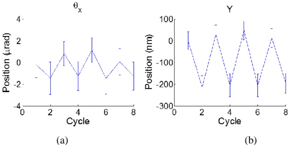
The amount of reduction in the vertical motion of the ball for a given force input is predicted to be equal to the value calculated in (2.40). For the prototype, this ratio was predicted to be 0.84. In early testing, it was observed that this effect induces a stage error that appears as a negative displacement of opposing half-groove assemblies (Figure 2.35). Iterative calibration eliminates this effect as explained in section 3.3.
𝐿𝐶𝐹 𝑅𝑎𝑛𝑔𝑒 𝑅𝑒𝑑𝑢𝑐𝑡𝑖𝑜𝑛 = 1 − (𝐾𝐻𝑎𝐺𝑟𝐻𝐺 𝐿𝐼𝑁𝐸𝐴𝑅,𝑍
𝐾𝐻𝑎𝐺𝑟𝐻𝐺 𝐿𝐼𝑁𝐸𝐴𝑅,𝑋) (2.40)
(a) (b)
Figure 2.35 (a, b): Reduction in travel appears as a negative displacement error in opposing half-groove assemblies

![Figure 1.5: The HPF is capable of both high accuracy and fine repeatability [25, p. 66]](https://thumb-eu.123doks.com/thumbv2/123doknet/14733718.573647/24.918.210.708.436.759/figure-hpf-capable-high-accuracy-fine-repeatability-p.webp)