The Design, Manufacturing and Use of Economically Friendly Injection Molds.
By Aaron Buchok
Submitted to the Department of Materials Science and Engineering in Partial Fulfillment of the Requirements for the
Degree of Bachelor of Science
at the
Massachusetts Institute of Technology May 15, 2008
© 2008 Massachusetts Institute of Technology All rights reserved
The author hereby grants to MIT permission to reproduce and to distribute publicly paper and electronic copies of this thesis document in whole
in any medium now known or hereafter creasel. , Signature of Author ... ... Certified by ... ... MASSACHUSETTS INSTmRTM OF TEOHNOLOGY
JUN 1,8
2008
LIBRARIES
MACHIVES
orin art -7 ... ... ... Aaron Buchok Department of Materials Science and Engineering May 15, 2008Dr. David K. Roylance Associate Professorbf Materials Engineering
Thesis Supervisor
Accepted by...
A ccep ted b y ... ... ...
Dr. Caroline Ross
THE DESIGN, MANUFACTURING AND
USE OF ECONOMICALLY FRIENDLY
INJECTION MOLDS.
BY
Aaron Buchok
Submitted to the Department of Materials Science and Engineering on May 15, 2008 in Partial
Fulfillment of the Requirements for the Degree of
Bachelor of Science
ABSTRACT
Much of the polymer manufacturing done today involves the process of injection molding. It can be difficult to gain experience in the art of designing and building tooling for this process outside of industry. The goal of this project is to simplify the process involved in the design of an injection mold to a level suitable for use by motivated undergraduate
engineering students. Discussion is centered on the state of the art of mold building. A great deal of attention is also paid to the use of the Battenfeld Plus 250 injection molder and the use of Solidworks MoldTools as tools for the design and use of mold tooling. By following the design, manufacturing, and use of a mold, a great deal of insight into the process and work required to produce the plastic items that we use every day is provided.
Thesis Advisor: David K. Roylance
Title: Associate Professor of Materials Engineering
ACKNOWLEDGMENTS
Many people have helped me along the way with the completion of this thesis. I'd like to take the opportunity to thank them for their hard work, support, and friendship.
I'd like to thank Mike Tarkanian for his help in acquiring the tools and materials needed to complete this work. His friendship and guidance has been a great support to me over this past year. He truly encompasses the following quote and I have learned so much from him and hope that I can repay him with my knowledge.
"A human being should be able to change a diaper, plan an invasion, butcher a hog, conn a ship, design a building, write a sonnet, balance accounts, build a wall, set a bone, comfort the dying, take orders, give orders, cooperate, act alone, solve equations, analyze a new problem, pitch manure, program a computer, cook a tasty meal, fight efficiently, die gallantly.
Specialization is for insects."
- Robert Heinlein, Time Enough for Love
I'd like to express my gratitude to Dr. David Roylance for his help and advice through the
process of constructing this document. He also helped me during my time here at MIT as my academic advisor and I hope that I have done justice to his teachings.
To Don Galler, whose lab I've lived in for the past four months and whose tools I've borrowed every day. I wish I had met you earlier in my time at MIT as you possess experience that is truly humbling. Thank you for sharing.
There are no words to describe the amount appreciation that I have for my fiance Katie. It is only through your support that I've survived some of the toughest times of my academic career and I hope that I can repay you by remembering that there is so much more to life than work.
Finally, but not at all least, I'd like to thank my family for the enormous amount of support they've provided me with during my time here at MIT. Without their support I never would have gotten far enough to be writing these acknowledgments.
CONTENTS
A bstract ... ... 3
A cknow ledgm ents ... ... 5
Contents ... ... 7
List of Figures ... ... 9
List of Tables ... ... 11
D esign... ... 13
1.1 Background and M otivation... ... 13
1.2 Current State of the Art ... ... 14
1.2.1 M old M aterials ... 14
1.2.2 M old Fram es... ... 16
1.2.3 Current Lim ited Production M olds ... ... ... 18
1.3 Concept ... 20
1.4 M old Carrier D esign ... ... 22
1.5 D esign Tools ... ... 25
1.6 D esign of M old inserts ... ... 27
1.6.1 Constraints on Part Geom etry ... 27
1.6.2 Exam ples of Injection M olded Parts ... ... 31
1.6.3 Creating a m old Insert In CAD ... 34 Page 7
Construction of Mold Carriers and Mold Inserts ... 36
2.1 THE DSME 3-Axis CNC Machine... ... 36
2.1.1 CN C M achining ... ... 36
2.1.2 The Southwestern Industries 3-axis CNC mill ... ... 39
2.2 Mastercam and G-code ... 41
2.3 Mold Alignment, Sprue Taper and Surface Finish ... .... 42
2.4 Test Fitting of M olds... ... 44
2.5 Notes on Mold Manufacturing...45
Use of The DSME Injection Molder ... 48
3.1 Introduction to the DSME molder ... .. ... 48
3.2 B attenfeld Safety... ... 53
3.3 A ssem bling the M old ... ... 55
3.4 Raw Material Handling and Setup ... .. ... 59
3.5 Operation of the Battenfeld Molder ... 64
3.6 Notes on Battenfeld Injection Molder ... 67
3.7 C onclusion ... ... 70
Bibliography ... 71
Appendix A: Technical Drawings of a Modular Injection Mold Frame ... 72
LIST OF FIGURES
Figure 1.1 M.U.D. frame loaded with ASTM test sample mold... 17
Figure 1.2 L.F.M mold carrier for student projects ... ... 20
Figure 1.3 Final design of mold carriers and ejector assembly ... 23
Figure 1.4. MoldFlow Xpress analysis of CAD model. ... .... 26
Figure 1.5. CNC verification using simulated CNC Mill. ... 27
Figure 1.6. The parting Line and Parting Surface. ... 29
Figure 1.7. Thickness Effects. ... ... 30
Figure 1.8. Common solutions to warp and sink effects ... ... 31
Figure 1.9. Injection M olded Parts ... ... 32
Figure 1.10. Parting line and cavity for a billiard ball. ... 32
Figure 1.11. Parting line and parting surface for a safety glass lens...33
Figure 1.12. Cavity and mold geometry for a non-planer parting line. ... 34
Figure 2.1. End mills of various sizes and geometries...37
Figure 2.2. A typical stepping down arrangement. ... ... 38
Figure 2.3. The DSME 3-Axis CNC Machine ... ... 40
Figure 2.3. The DSME 3-Axis CNC Machine ... ... 42
Figure 2.5. Mold Polishing by a skilled craftsman. ... 44
Figure 2.6. Using a diamond saw to grind ejector pin to length ... 47
Figure 3.1. Battenfeld Plus 250 Injection Molder ... 48
Figure 3.2. M.U.D. Frame with ASTM Test Sample Mold Installed ... 50
Figure 3.3. Calibration Data for DSME Battenfeld Plus 250/50 Molder (Pressure) ... 51
Figure 3.4. Calibration Data for DSME Battenfeld Plus 250/50 Molder (Shot Volume) ... 51
Figure 3.5. The Temperature Control Unit and Mold Plumbing ... 52
Figure 3.6. TCU Backside Plumbing ... 53
Figure 3.7. Assembly of the sprue side carrier and insert. ... .... 56
Figure 3.8. Assembly of the ejection side. (from left to right, top to bottom) ... 57
Figure 3.9. A smiley face should greet you if the installation was done correctly ... 58
Figure 3.10. The ejector pin stroke must be set ... 59
Figure 3.11. Raw Resins as Delivered ... .. ... 60
Figure 3.12. The Error K ey ... ... 64
Figure 3.13. The manual control switches. ... 66
Figure 3.14. The cooling system regulator bank. ... 68
LIST OF TABLES
Table 1.1. Common M old Building M aterials ... 16
Table 3.1. Injection Unit Specifications... ... 49
Table 3.2 Common Injection Molded Material... ... 63
Table 3.3. Common Control System Errors. ... 65
CHAPTER
1
DESIGN
1.1
BACKGROUND AND MOTIVATIONInjection molding is a manufacturing method by which large quantities of small to
medium size objects can be produced from low melting point materials. From food
containers to computer cases, many of the plastic products that we use today are
manufactured by injection molding. Liquid material (usually plastic, zinc, brass, or
aluminum) is injected into a mold constructed from steel or aluminum. This mold contains
the liquid material while it solidifies within a cavity. After the part has cooled, the mold
opens up and the part is ejected.
In 1865 Phelan & Collendar, a prominent billiard ball manufacturer, promised
$10,000 to anyone who could find a suitable replacement for ivory, which was becoming
harder and harder to procure. It was in 1869 that John Wesley Hyatt, a commercial printer,
discovered nitrocellulose. Rumor has it, that Hyatt didn't cash in on the prize but instead
founded his own billiard ball company, Albany Billiard Ball Company. By injecting
nitrocellulose into a mold and allowing the solvents to evaporate, Hyatt was able to produce billiard balls in a quick and repeatable process. John and his brother Isaiah were
awarded a patent in 1872 for their design of the first injection molding machines. (Osswald, Turng, & Grammann, 2008)
Today we find that almost all consumer products have some components that are made by this process. It takes a great deal of searching to find a single product that isn't in some way affiliated with injection molding. This extremely popular mass production tool is widely relied upon because of its ability to produce dimensionally stable parts for many cycles and to do so at very little cost per unit. Whether it's film canisters or automotive dashes, injection molding provides the means for huge production numbers at final costs that closely approach the raw material costs.
The high initial cost of injection molds often makes this process available only to industry and only for projects where the requirements demand between 104 and 106 units to be manufactured. It's not uncommon for a simple production ready mold to cost
between $30,000 and $60,000. Some extremely elaborate molds can cost up to $800,000. These high initial costs have all but eliminated hands-on experimentation from academic study. It is only through experimentation and the design of molds that a student can truly come to appreciate the art of injection mold design. Keeping this idea central to my
motivation, I've created a system by which a student can design, make, and use an injection mold for less than $100 over the course of a semester.
1.2 CURRENT STATE OF THE ART
1.2.1 MOLD MATERIALS
Injection molds that are built to operate in a mass production environment are typically built from metals that have been specifically alloyed for that purpose. In order for a mold to survive for tens of thousands of molding cycles, there are a few conditions that must be accounted for. The largest consideration is the thermal characteristics of the mold itself. In a production environment, the speed of the production line is dominated by the cooling time needed for a part to solidify. The economic motivation for fast cooling has seen an increase in the presence of copper and aluminum based molds in recent years due to their excellent thermal conductivities.
The second most important characteristic is the material hardness. In the past, this requirement necessitated the use of steel alloys for almost all production molds. Even today, the steel mold is still one of the most common materials seen on production lines. The high hardness, prevents wear to the cavity walls and serves to expand the life of the
expensive mold.
The last critical requirement for a mold material is it's ability to be shaped by conventional manufacturing operations such as CNC milling and Electrical Discharge Machining (EDM). As a general rule, the harder the material is, the longer it will take to obtain a mirror surface on the mold cavity. This rule is however starting to break down as we see more purpose specific alloys becoming available to the mold designer. Table 1.1 below, compares some of the more common injection mold building materials.
Material Thermal Thermal Hardness Dominant Producer
Conductivity at 68*F Diffusivity at (Brinell) Component
(Btu/ft/hr/ftA2/°F) 68°F
ftA2/hr
MoldStar 150 2.32 210 Copper Performance
150 Alloys
QC7 80 2.44 167 Aluminum Alcoa
Tool Steel- 20 0.39 345 Iron Varies
P20
Tool Steel- 17 0.31 530 Iron Varies
H13
Stainless 7 0.14 190 Iron Varies
Steel
Table 1.1. Common Mold Building Materials (From Performance Alloys)
All custom alloyed mold materials carry fairly high price tags. A single set (2 pieces) of 3.5"x 3.5" x 1.25" pieces of Cu-based mold material were quoted to me at just over $950. While a production mold builder is willing to pay for the added performance of these
materials other short run production lines are not capable of spending six figures on a mold that they will never recover the cost of. Most short run injection molds are built with
common aluminum alloys such as 7075-T6, 2024-T4 and 6061-T6. These molds are
particularly susceptible to wear and are typically used in prototype and limited production runs.
1.2.2 MOLD FRAMES
There are very few industries that can justify the purchase of a modern injection molding machine to manufacture the same part for its entire lifetime. The necessity of the molding machine to accept multiple molds over its lifetime and to minimize the amount of downtime has produced a necessity of the injection molding shop, the mold frame. The
mold frame allows for a machine to accept a number of molds and minimizes the downtime of the machine. A typical mold swap on the DSME molder takes about 10 min. with this system. Without the use of a mold frame, the same mold swap might take five hours to a full day.
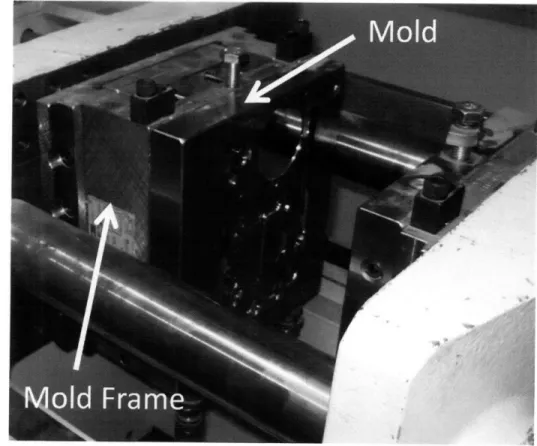
The dominant mold frame for the entire molding industry is Master Unit Die's "M.U.D." frames. These frames bolt to the platens of the injection molder and is aligned to the machine, then molds are dropped into the frame from above. Figure 1.1 shows a picture of the DSME M.U.D. frame loaded with a mold for producing ASTM test samples.
Figure 1.1..M.U.D. frame loaded with ASTM test sample mold.
As these mold frames are a standard item in industry and extremely useful for the setup of molds I've decided to built my modular mold to fit within the existing M.U.D. frames. This allows the user to setup the ejector pins, return pins, alignment pins and cavity at the comfort of a workbench before bringing it to the machine. Since it is extremely important to maintain the faces of the mold as pristine as possible, this approach helps to prevent mold damage by giving the user sufficient workspace to perform maintenance on their molds. I was able to determine at the DSME molder is currently using a MUD U-84/90 model mold frame and after contacting Master Unit Die and explaining why I need them, M.U.D. was able to provide me with technical drawings of their frame to use in the design process.
1.2.3 CURRENT LIMITED PRODUCTION MOLDS
The most common approach to the building of limited production molds involves purchasing mold blanks from M.U.D. which are appropriately sized for their mold frame. Most mold blanks are designed with a tong and groove system that allows them to be dropped into the mold frame and prevents movement of the mold relative to the machine platens. These mold blanks are typically steel units that need the cavity, gates, and runners machined into them. They are available for about $500-$800 per set depending on the depth of the mold. Some aluminum (QC-7) units are available at an extra cost. For most experienced machinists and mold makers, who have the background to assure that design and manufacturing mistakes are kept at a minimum, this can prove to be the best option. There is however, a disconnect between practical experience and theoretical
understanding in the art of mold building that prevents the purchase of these units for the novice designer. It would be much better, if a student was able to experiment and practice their building on economically friendly $5 mold blanks.
This approach is the same that has been used by several other universities to allow for injection mold building experience at the undergraduate level. The most prominent of these is the Mechanical Engineering Department at MIT. They offer a junior level class on
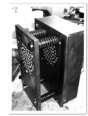
manufacturing each year where 80-100 students design and manufacture their own injection molds. The cost of the class is kept to a minimum by using a set of M.U.D. mold blanks that have been pocketed out to allow a student to machine an insert that gets bolted into the blanks which is then inserted into their mold frame. According to the staff and students the class has proven to be a success and is relatively economically friendly. In preparing for my mold design, I visited the Laboratory for Manufacturing and Productivity to speak with their staff and learn a little about their apparatus. I loved their approach to low cost, low risk, mold inserts but didn't like their ejector pin setup or the lack of a true alignment mechanism between the two halves of the mold. Their apparatus is also extremely heavy, which makes loading the whole thing into the molder very difficult by hand.
Figure 1.2. L.M.P. mold carrier for student projects
Other universities have tried other approaches including micro sized mold frames that accommodate a 3" x 3" mold face or removing the mold frame altogether and making students bolt their molds directly to the platens of the machine. After examining each of the options currently available, I decided to approach a design similar to MIT's but to address the shortcomings in their design. By observing their system and speaking with students I was able to modify the design to account for the design features that users find most troubling.
1.3 CONCEPT
The approach I chose to pursue was a set of mold carriers that dropped into a MUD U 84/90 mold frame. These mold carriers would incorporate pockets in each side (sprue
and ejector) where a student can mount their mold inserts. Mold inserts will be
approximately 3.5" x 3.5" x 1" and the mold carriers will allow them to be bolted in multiple locations to permit multiple sprue locations. There will be a central sprue location for molding cylindrically symmetric items and a low sprue location that allows parts to be filled from the bottom in order to minimize the turbulence in the plastic flow.
The alignment between the two mold carriers will be accomplished with four steel alignment pins that have been heat treated and then ground to produce a zero lash
alignment between the two carriers. Alignment between the mold inserts and the mold carriers will be accomplished with the use of two Y4" dowel rods.
The mold inserts will be held in place with two ¼"-20 socket cap screws with recessed heads. The ejector pin assembly will consists of the traditional ejector pin plate and pusher plate but will be drilled to accept more than 200 different ejector pin locations. The molder uses a plunger to actuate the ejector pins forward and I'll use a set of four return pins to retract the ejector pin plate. As the mold closes, the return pins will push the ejector pins back and will position the pins to their "home" positions at the moment when the faces of the mold inserts meet. Without preloaded springs to return the ejector pin plate, the assembly of the mold carriers should prove to be easy.
Ejector pins will need to be cut to the appropriate length through the use of a diamond blade. The saws used to prepare metallurgical samples for microscopy have proven to be an excellent tool for this as they allow for nearly perfect surfaces and can cut the rods to the necessary length with the desired precision.
Getting the alignment of the two pieces correct has proven to be the most difficult aspect of the design. By using a complex manufacturing schedule of elaborately planned
CNC processes, the alignment of the mold inserts should be able to be maintained at
+/-.001" relative on one another. The CNC machining will be completed in as few finishing operations as possible and with minimal tool changes to avoid any unnecessary
misalignment. This will limit the variance in the dimensions to that of the machine itself which the manufacturer has tested to be within +/-.0002".
Another aspect that has proven to be challenging has been getting the faces of the mold inserts to contact with the correct amount of pressure and preventing the faces of the mold carriers from absorbing the load before it can build up on the insert faces. By setting the face of the insert slightly higher than the face of the carrier, I believe that I can load the face with sufficient closing pressure to produce high quality parts. The DSME Battenfeld Plus 250 machine is capable of producing over 250 tons on clamping load so it will be necessary to setup the machine to limit it's clamping action so the mold inserts are not permanently deformed.
1.4
MOLD CARRIER DESIGN
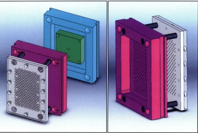
The design of the mold carriers was conducted as an iterative process where a preliminary model was designed, digitally tested and then changes were made. The final product after taking into consideration the design constraints imposed by the mold frame, the Battenfeld injection molder and the mechanical constraints of the mold carriers is shown in figure 1.3.
Figure 1.3. Final design of mold carriers and ejector assembly.
On the ejector side (shown in pink), the carrier has been drilled to allow 218
different ejector pin locations. It also has bolting locations and alignment pin holes to allow for three different locations that the mold inserts can be installed in. The return pins
(shown above in dark grey) are a 4.000" overall length with a 1/8" lip on the back edge to prevent the pins from pulling through the ejector pin plate (shown in light grey). A set of brass bushings guide the hardened steel return pins and prevent them from wearing into the aluminum carrier. These bushings are epoxied in place in order to prevent them from being pushed forward or back by the movement of the return pins. Both the pins and bushings were purchased from MSC Direct and the ejector pin plate is designed to accept 3/32" ejector pins, also available from MSC Direct.
The mold insert (seen above in green) has specific bolt and alignment hole locations but will permit the use of several different sprue locations that the designer can choose from. This flexibility allows for various molds to be created and a sprue positioned in the optimal location. Cylindrically symmetric parts will most likely benefit from a center oriented sprue with gates and runners oriented outwards. Other parts will benefit from a bottom filling orientation that allows for the runners, gates, and cavity to fill from the bottom up. The flexibility with the mold inserts also allows for the designer to specify various mold materials such as copper, steel, or tungsten. Typically the cost involved with these molds would exclude them from use in a learning environment, but with the smaller volume of material needed, they become more financially friendly.
The channels on each side of the carriers serve to align the carrier to the mold frame while maintaining the drop-in capacity that was desired. They are sized and positioned in such a way as to spread out the load when clamped across eight different surfaces where the mold carrier contacts the load frame. Getting each of these surfaces accurately
positioned relative to each other could not have been accomplished without a complete set of technical drawing of the MUD frame. By distributing the load between multiple surfaces, the service life of the aluminum carriers can be extended greatly.
For completeness, a full set of technical drawings in included in appendix A. These documents represent all the necessary geometry and dimensioning needed to redraw or remanufacture these parts at any time in the future. I've included them in an effort to archive the complex and time consuming CAD models in a format that isn't subject to loss due to computer malfunctions.
1.5
DESIGN TOOLS
Since the mold carriers, ejector pin plates, mold inserts, and the pusher plate needed to be CNC machined, a full CAD model of the apparatus was necessary. A copy of Solidworks was obtained from MIT's Department of Mechanical Engineering to accomplish this task. By first modeling the MUD U 84/90 mold frame I was able to fit the mold frame to the mold carriers to assure a secure fit within the frame. Having nearly nine years of CAD experience allowed me the freedom to experiment with three different ideas without needing to construct prototypes.
Solidworks incorporates a finite element analysis (FEA) package into its basic software with allowed me to conduct some basic modeling of the stresses within the mold carriers when they were in operation. Unfortunately, fatigue modeling is must less reliable in FEA and so the maximum loads in the mold carriers were kept to 138MPa which should provide sufficient strength to achieve 108 cycles (Matweb.com).
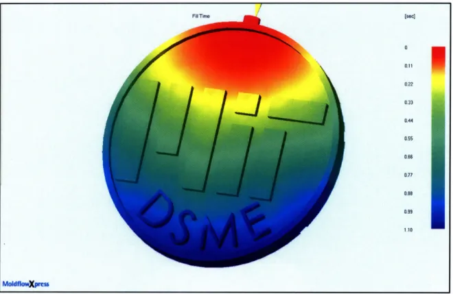
In addition to the modeling of the carriers and ejector assembly, a few simple mold inserts were designed. By first modeling the final part, Solidworks is capable of producing a set of mold inserts that will produce the desired part. These tools analyses the draft angles of the part to make specific recommendations on where to position the parting line and the integrated copy of MoldFlow Express helps the designer to position the gate in the best possible position. MoldFlow takes into account the melt temperature, mold temperatures, injection pressures, times and viscous flow characteristics and outputs a model of the fluid
flow within the cavity. These results allow you to change the injection profile digitally before ever setting up the molder.
Figure 1.4. MoldFlow Xpress analysis of CAD model.
The CNC machining will be orchestrated by G-code generated with Mastercam X2. Mastercam is the standard tool used to generate machine code from computer models. By properly setting up Mastercam to speak the same language as the DSME Southwestern Industries CNC mill and providing the necessary details on the material and cutting tools, a complete set of instructions were generated. These instructions were then verified using a simulated CNC mill through a software package called Vericut (v.7). Only after the
simulated mill was able to verify the quality of the g-code is the program loaded into the CNC machine. Page 26 [sec] 0 0.11 0.22 0.33 0.44 0.55 0.66 0.77 0.088 0.99 1.10 - 5mflkwxpmu i I
Figure 1.5. CNC verification using simulated CNC Mill.
1.6
DESIGN OF MOLD INSERTS1.6.1 CONSTRAINTS ON PART GEOMETRY
Page 27
When considering if injection molding is a viable manufacturing method for your part, it's important to consider a few criteria.
1) Is the part hollow? 2) Are there any undercuts?
3) How many parts must be made? 4) How big is the part?
Hollow parts are difficult to injection mold and require the use of a sacrificial plug, Injection molding should be the last resort for these items if rotational molding cannot be utilized.
Undercuts prevent molded pieces from being removed for the mold and cannot be made using injection molding.
If you need to make a small number of pieces, 3D printing may be a better option. If all your parts must be microstructurally identical then injection molding is your best bet.
The DSME molder is only equipped to handle small to medium sized (Button to Calculator sized) items. The larger the part is the more material is needed to fill the mold cavity, runners, and sprue. The maximum shot capacity of the Battenfeld Plus 250 is only -49cm 3
When looking at a part and determining how to design an injection mold for it, it helps to think about the so called "parting line" of the part. This line can usually be seen on injection and blow molded items such as toys and bottles as a thin riser of material where the two mold halves meet. In clear water bottles, the molding lines cause optical distortion and are easily seen.
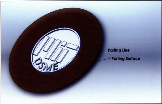
It helps me to think of the parting line as a parting surface. When evaluating a part, think about a surface that you could add (of zero thickness) that would effectively isolate the front and back surfaces. Figure 1.6 shows a parting surface for a 1.25" plastic coin.
I
I
Figure 1.6. The parting Line and Parting Surface.
The coin shown in figure 1.6 can have all of its featured reached by a mold as it has no undercuts on the front side (shown) or the backside (not shown). The parting surface will determine which features are created by each of the mold halves. Everything on one side of the parting surface will be on the Sprue Side (or A side) of the mold and everything on the other side will be located on the Ejector Side (or B side). Cosmetic parts should always be oriented such that the visible face be created by the A side of the mold. In almost all injection molded items, there is evidence of the ejector pins on the B side of the part.
Ejector pins serve to push the molded part out of the mold so that the molding cycle can continue.
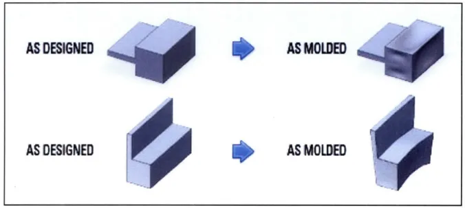
Thick bosses (such as screw standoffs) should be avoided, as they cause sinks on the backside of the part due to the shrinkage of material during cooling. Instead, use thin
bosses and tie them to other features with thin walls. The effects of differential cooling within the part can cause extremely undesirable features in your parts Figure 1.7.
AS DESIGNED
AS DESIGNED
AS
MOLDED
AS MOLDED
Figure 1.7. Thickness Effects. Image courtesy of ProtoMold Inc.
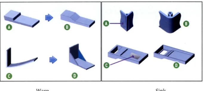
Keeping the part as uniformly thick as possible can reduce the effects that differential cooling have the part geometry. The two phenomenon seen in Fig 1.7 are referred to as "sink" in the top part and "warp" in the bottom part. Both warp and sink can be avoided by modifying the part to create a more uniform thickness. In the case of warp, gusseting can be utilized to avoid bending but will result in residual "molded in" stresses.
Figure 1.8 demonstrate some common solutions to warp and sink.
VF
Warp Sink
Figure 1.8. Common solutions to warp and sink effects. Image courtesy of ProtoMold Inc.
1.6.2 EXAMPLES OF INJECTION MOLDED PARTS
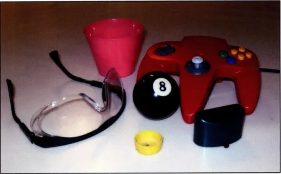
In Figure 1.9, there are a six items shown that have been manufactured using injection molding. In order to reinforce the idea of the parting line and surface, each item will be imported into a CAD program and the parting line, parting surface and a simple injection mold will be shown for a few of the items.
Page 31
0-
0
Lvo-
'O
0
0--
0
W%7
Figure 1.9. Injection Molded Parts
The first item we'll look at is the billiard ball. With its multiple degrees of symmetry, the choice of parting line is arbitrary as long it passes through the ball at the two poles.
Figure 1.10. Parting line (left) and cavity (right) for a billiard ball.
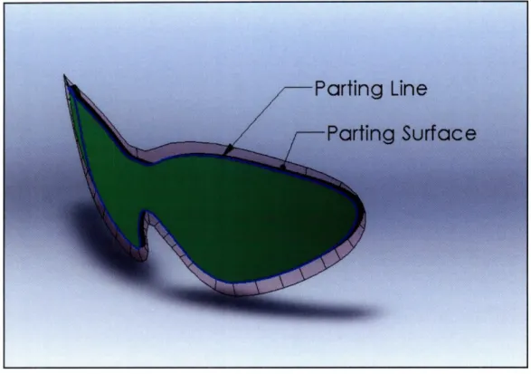
The second example involves a more complex geometry that produces a non-planer parting surface. This geometry necessitates the use of more complex mold geometry. Figure 1.11 shows a CAD model of a lens for a set of safety glasses. Typically these are manufactured from polycarbonate using injection molding. The parting line originates at
the top-most edge of the lens and because the parting line cannot be contained in a single plane, a complex parting surface is necessary to produce the desired mold geometry.
I
I
Figure 1.11. Parting line and parting surface for a safety glass lens.
The more complex mold geometry that is necessitated by the non-planar parting line is shown below in figure 1.12. Two bosses of material extend from the mold faces and contain the cavity at their topmost face. The ejector pins, gate and sprue are all contained within these bosses also. Many mold designers like this type of mold because it adapts well
to a technique referred to as "hot runner" molding. By adding heating units around the runners and gates of the mold, parts can be produced without any of the normal waste. This technique involves a great deal of understanding of the cooling within the mold and the accurate timing and control of the molding cycle. Most industries are slowly starting to utilize more "hot runner" systems as the presence of FEA modeling for heat flow become more accessible to the designer.
Figure 1.12. Cavity and mold geometry for a non-planer parting line.
1.6.3 CREATING A MOLD INSERT IN CAD.
There are very few geometries that can effectively be designed and manufactured without the use of a computer aided design system (CAD). Through the use of CAD, a designer can test fit their design into other CAD models to ascertain if the final assembly will come together as expected. Appendix A contains complete technical drawing of the mold carriers and a recommendation on the geometry of the mold insert. In actuality, any mold insert can be bolted into the molder if the insert can fit within the confines of the mold carrier's pockets. By first modeling the carriers and the mold inserts, the designer is able to determine the placement of the sprue, gate, and ejector pins. This tool gives the designer the assurance that once manufactured, the mold inserts will in fact fit into the carriers are desired.
Page 34
The first step in designing an insert is to model a blank mold insert and the carriers. By first modeling the assembly you can assure that the mold insert will fit into the carriers and you can use the carriers as a template to create the sprue and ejector pin holes. It is highly recommended that the sprue and ejector pin hole be in place on the mold blank before creating the cavities or the runner system.
Nearly all commercially available CAD software contains a set of mold creation tools. In all of these tools, you first need to create a model of the item you want to mold. Each software package is different, but the tutorials will show you how to remove material from the mold blanks that resembles the negative of your original model. The implementation is such as the designer must specify the parting line of the part and the software will create the parting surfaces and create the cavity. The most common CAD packages (Solidworks, Pro/Engineer, Autodesk, AutoCAD) all contain a set of "mold tools" these tools assist the designer in determining the draft on the model and creates the important parting line. The draft is an important aspect of the part design. By adding a small taper to each flat face, you can assure that the molded part, once cooled can easily be removed from the mold. None of the CAD packages I've worked with will allow you to create the parting line if there isn't at least some draft applied to the model. Typically, the drafting of a model is done using a "draft" function combined with the designers input on the pull direction.
CHAPTER
2
CONSTRUCTION OF MOLD CARRIERS AND MOLD INSERTS
2.1 THE DSME 3-Axis CNC MACHINE
2.1.1 CNC MACHINING
As part geometries become more complex, industry has adapted their tools to better
accomplish their work. One such type of tool is the computer numerically controlled (CNC) cutting tool. These machines use computer instructions to move a cutting bit around a piece of stock material. These movements are programmed with a computer aided
manufacturing (CAM) software using the CAD models as guides. Section 2.2 will focus more specifically on the use of CAM and the role it plays in creating mold inserts.
The three axis CNC machine allows the operator to manipulate a cutting bit in three orthogonal directions at any time. These movements are controlled by rotary encoders affixed to three handles. Due to the complexity and the lack of coordination, it's nearly impossible for a person to manipulate more than one of these axes at a time with any deal of precision. In the 1950's, a professor at MIT, John T. Parsons created an electronic control system that would move the X and Y axes with the coordination that people lacked. It was
through the use of these electronic control systems that mills were finally able to machine precision shapes that involved curves. In the years since that achievement, full 3-axis CNC machines have become commonplace and there are even 5 and 6 axis machines available to industry.
CNC machining is inherently a subtractive process where unwanted material is removed from a piece of stock until the desired geometry is revealed. The process is similar to that used by a sculptor when they remove pieces of marble from a larger piece to reveal the statue inside. Unlike the chisels used by the sculptor, CNC machines use cutting tools called end mills (Figure 2.1). These cutting tools are available in many different sizes and geometries. A typical end mill is specified by the type of material the tool is constructed from, the size, the geometry, and the number of flutes. These flutes serve to remove the scrap material from the cutting surface and keep the tool cool by preventing unnecessary friction heating.
Figure 2.1. End mills of various sizes and geometries
The choice of what cutting tool to use is largely based on the amount of material you want to remove. Larger tools give you a higher rate of material removal at the sacrifice of
Page 37
m m
detail. It's very difficult to get highly detailed features out of a large end mill. This difficulty has lead to the process of stepping. Initially, a larger end mill is used to remove the bulk of the material as part of a "roughing" operation. Then a smaller end mill is employed to remove the small amount of left over material and produce the fine detailed features. The fine details are revealed during the finishing operation. It's not uncommon for there to multiple steps between the roughing and finishing passes. Through the use of stepping, you are able to produce very detailed features at fraction of the time it would take to do it with only one small tool. There are other reasons that stepping is preferred to single tool operations, such a tool wear and breakage. By stepping down, you avoid unnecessary tool wear and some jobs can just be too aggressive for small end mills resulting in a broken tool.
Figure 2.2. A typical stepping down arrangement.
Some end mills are available in different tip geometries. The two most common are the square and the ball end mill. Square end mills are perfect for producing features with squared off faces and pockets whereas the ball end mill is intended for producing sweeping curved surfaces. Other tool geometries are available but are fairly uncommon. The most
notable of these is the radiused square end mill. These end mills have a square face with a small (-0.020") radius on the outside cutting edge. This radius allows for the detail of a very small ball end mill with the strength of a large square end mill. The reason that I mention the radiused end mill is that they are purposely designed for the creation of molds.
It's fairly common practice for end mills to be purchased specifically for a project, and as such, end mill selection based on current availability is usually a bad decision. It is highly recommended that the right end mills be purchased for any given project.
2.1.2 THE SOUTHWESTERN INDUSTRIES 3-AXIS CNC MILL.
The Department of Material Sciences and Engineering currently owns and operates a 3-axis CNC mill. This mill was obtained in January of 2008 and has been a welcome addition to the department. It was manufactured by Southwestern Industries and is an open bed type mill. This design allows for large pieces of raw material to be installed in the bed. An enclosed type mill is usually limited in the size of part that can be contained within the machine. The mill is capable of operating in either full CNC or manual mode and gives the operator the freedom of a CNC mill with the versatility of a manual mill.
Figure 2.3. The DSME 3-Axis CNC Machine
In full CNC mode, the mill receives its instructions from either a CAM produced program or the Prototrak control system. The Prototrak control system is equipped with an intuitive programming interface that allows for simple CNC programs to be written on the mill itself. As a general rule, anything that requires CNC operation for 2D features (confined to the X-Y plane) should be programmed on the mill while all 3D features must be cut using a CAM produces set of instructions.
The total travel of the machine is confined to a 60"(x)-24.25"(y)-13.5"(z) envelope. With the variable speed option, the mill is capable of 5000rpm and is driven by a 3hp motor. Tooling can accurately be moved at up to 100 ipm with a resolution of +/- 0.0002". The onboard memory limits the size of CAM file to 512mb which is sufficiently large that it should never be an issue in roughing operations but could interfere with finishing
operations. It has been necessary at times to create two sets of instructions for the mill composing roughing movement in one file and finishing operations in the other.
2.2
MASTERCAM AND G-CODEAccompanying the mill purchase, a full suite of Mastercam was also purchased for use by DSME students. The Mastercam suite of programs allows for instructions to be generated for CNC machines. This code is commonly referred to as G-code in the US/China and M-code in Europe. G-code contains instructions for the mill on when an axis should begin to move and at what rate. Most G-code is a set of vectors indicating the travel of the cutting tool but there are other built in features that specify the tool number, cutting speeds and feeds, and several preprogrammed mini-programs.
A full set of tutorials is available for Mastercam and is available in a lesson format
that exposes the user to a skill set that enables them to adapt quickly to different
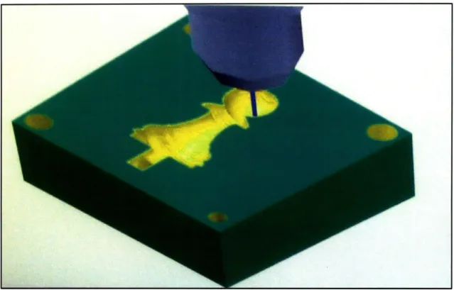
geometries. These tutorial were consulted in the production of a set of inserts for the 3.042 class during the spring 2008 term. A set of molds were created to make plastic pawns as part of a chess project. The molds were first modeled in Solidworks and then imported into Mastercam. After the software had the necessary information about the CNC mill (such as spindle speed, travel, hp rating, etc..) and the size and geometry of our rough stock, toolpaths were created to remove material. Each toolpath was programmed based on the model geometry so that Mastercam had a clear idea of what geometry was specified. Several different types of end mills were used in the construction of the toolpaths. We employed a stepped process that started with a 1/8" square end mill and finished with a
1/32" ball end mill. Each mold half took nearly 8 hours to produce with the majority of that time spent in the finishing pass where each path was 0.002" spaced from the previous path. This meticulous attention to surface finish produced a surface that did not need polishing in order prior to use.
Figure 2.4. CNC Mill executing Mastercam-generated G-code.
2.3 Mold Alignment, Sprue Taper and Surface Finish
The quality of the final part will largely be determined by the quality of the machining that went into the mold creation. Each half of the cavity must be correctly aligned to the other half when they come together in the mold. For this reason, it is suggested that a fixture be utilized to secure the mold blank to the mill bed. By using a fixture, the workpiece zero is removed from the piece of stock that is installed in the mill.
This practice will produce mold inserts that are perfectly aligned to one another regardless of the shape of the mold insert blanks. This is a rather advanced practice and an
experienced machinist should be consulted prior to making and using a fixture. The sprue on the mold insert must have a slight taper to it in order to demold properly. Without the taper, it will be difficult to remove a molded piece from the mold as the sprue will hold on to the part. It is suggested that the sprue be cut using a 1/8" pilot hole and a 50 tapered drill bit with a small end diameter of 0.250". These drill bits are available from mail order industrial supply companies and can save hours of removing stuck pieces.
The better the surface finish is on the faces of the cavity, the better the molded part will appear. The surface texture of the mold will be imprinted on the outside surface of the part and therefore attention should be paid to the quality of the cavity surface. After
machining, no metal tool should touch the cavity faces. It has been necessary at times to enhance the surface using small handheld polishing tools (-.5" diam.) attached to a Dremmel type tool. If surface texture is extremely important, there are specialized
craftsmen that spend years perfecting the tools necessary to perfectly polish an injection mold. The skills necessary for this type of operation is beyond what can be learned in the course of a few years and molds that need that level of surface preparation should be machined and then sent out for polishing.
Figure 2.5. Mold Polishing by a skilled craftsman.(Image courtesy of Pioneer Plastics) In order to obtain the best possible machined surface, the goal is to minimize the material removal rate. This is typically done by specifying a step depth of -0.005" and running the end mill at high speed and very low feeds. This principal is largely the reason that finishing passes take so much longer than roughing operations.
In the past few years a great deal of interest has be generated on the use of electroplating as a tool for surface preparation of molds. Because electrodepositing is an inherently self leveling process, this allows for quick surface preparation at atomic level smoothness. There is only one company in the Boston area that provides this service and they only recommend it for the purpose of building up the cavity walls with copper
deposits prior to hand buffing and polishing.
2.4 Test Fitting of Molds
Prior to use, every injection mold insert needs to be fitted to the carriers. The mold inserts should first be assembled into their carriers using down pins and socket cap screws
to securely attach and align them. The two carrier should then be assembles on top of each other. Special attention should be paid to the alignment between the carriers during this step. In order to test the mold alignment, hot wax should be pored through the sprue and allowed to cool. After sufficient cooling, the mold should be disassembled and the wax piece analyzed. If there is excess flashing around the parting line, it will be necessary to utilize a spacer plate between the ejector side carrier and mold insert. These spacer plates should never be used on the sprue side as they can cause the sprue to become stuck in the mold and the mold will have to be disassembled to get the molded part out.
Alignment issues between the two pieces are indicative of poor alignment during the machining process and cannot easily be fixed. The simplest solution is to
remanufacture the mold inserts if the alignment is critical.
Once the alignment is verified and any spacer plates installed, the ejector pin holes must be drilled out. It is preferred that the ejector side carrier be used as a guide for this operation. This technique allows the builder to drill through the spacer plate and the mold insert at the same time assuring that the alignment is perfect. Ejector holes should be drilled with a 3/32" carbide drill bit in order to assure that no molten plastic is allowed to flow between the mold and the ejector pin.
2.5 Notes on Mold Manufacturing
Some of my general observations on the mold insert manufacturing process are presented below. Even with years of experience in CNC machining and manufacturing
planning, I still find fault in my process as I work through a project. These are just a few of the observations that are based largely on mistakes experienced during the mold insert manufacturing process.
There is no such thing as being too obsessive about the mold alignment. Every time that the workpiece is removed from the mill, the alignment gets a little worse so try to complete all the machining without removing or rezeroing the workpiece. The use of a fixture for holding the mold inserts is a great idea in my opinion as it gives the machine a zero for the workpiece that is not dependant on the tolerances of the piece of stock. The pawn molds produced by the 3.042 class clearly demonstrated that the use of the stock piece as the zero doesn't give a precise alignment and should be avoided unless the stock material has ground perpendicular faces.
By waiting for ten to twenty minutes between the roughing and finishing passes, you let the mold insert cool sufficiently such that the thermal expansion experienced by the roughing pass is allowed to subside. Extremely precise molding projects are often
machined in an environmental chamber that simulates the operating environment so that the thermal expansion is not an issue during production.
With some mold designs, it can be hard to get the part to pull out of the sprue side when the mold opens. The best approach that I've found to solve this problem is to add a small threaded hole to the ejector side mold insert directly opposite of the sprue. The threads grab the part and pull the sprue out. This approach requires that an ejector pin be
added directly below the threaded hole to push the part out through the threads.
It is also recommended that the mold be drilled for the ejector pins after the mold halves are installed and using the carrier as a guide for the location of the hole. This approach has given very good results.
The ejector pins should be cut to length based on a metallurgical sample saw. The diamond blade produces a cut free of a burr that can prevent the ejector pin from being installed. This approach has been implemented in several instances with amazing results that are far superior to using a lathe or handsaw.
Figure 2.6. Using a diamond saw to grind ejector pin to length.
CHAPTER
3
USE OF THE
DSME
INJECTION MOLDER
3.1
INTRODUCTION TO THEDSME
MOLDERAt MIT, the Department of Material Science and Engineering currently own and operate a Battenfeld Plus 250/50 injection molder (Figure 3.1). It is horizontal
reciprocating screw type design manufactured in 1993. The moder uses a Unilog 1020 control system. Like all reciprocating screw machines, the geometry of the screw and plasticating unit are specific to the size and typical uses of a machine. Table 1 lists the important data related to the injection unit of the DSME machine.
Figure 3.1. Battenfeld Plus 250 Injection Molder
The injection unit of the Battenfeld Plus 250 is hydraulically actuated and is has a fixed funnel type hopper located above it. Material within the unit is heated through the shear forces on the material as well at the heating of the cylinder from electronically controlled heating clamps. The machine came from the factory with only two temperature controlled zones on the cylinder. It has since been retrofitted with a third zone at the nozzle and the control system has been modified to allow all three zones to be fixed at a constant temperature. Currently, the machine is set to use Fahrenheit and should remain in that setting as the calibration and setup of the machine will not self correct if changed to Celsius.
Injection Unit Units Plus 250/50
Screw Diameter mm 25
Specific Injection Pressure bar 1260
Theoretical shot volume ccm 49
Max. Shot Weight (Polystyrene) g 44.6 Max. Shot Weight (Polyethylene) g 34.8
Screw L/D ratio 14
Nozzle stroke mm 150
Nozzle Contact Pressure kN 35
Screw Stroke mm 100
Max Screw RPM min - 400
Screw Torque Nm 160
Plastification capacity g/s 12
Injection Rate ccm/s 74
Cylinder heating capacity kW 2.76
Number of heating zones 3 (nozzle, middle, back)
Table 3.1. Injection Unit Specifications
The clamping unit of this machine is also hydraulically driven and has been equipped with a Master Unit Die (MUD) mold frame (model 84/90 US 321). This mold frame allows for molds to attach to the machine quickly by dropping the molds into groves from the top (Figure 3.2). At present, the nozzle of the injection unit has been matched to
the MUD frame and molds need not be machined to accept the radius of the nozzle. Mold blanks can easily be purchased from Master Unit Die and then machined for the part cavity. The clamping unit of the Battenfeld machine also incorporates a hydraulically actuated ejection mechanism (26.2kN max) for pushing parts out of the molds should they need some force to be removed.
Figure 3.2. M.U.D. Frame with ASTM Test Sample Mold Installed
The Unilog control system of the molder is simple to use and the Battenfeld Unilog 1020 Manual focuses on its use. It is important to know that values for pressure for the machine and programmed in fraction of maximum pressure. Figure 3.3 shows calibration data to relate %P to injection pressure for our specific machine. The high precision hydraulic system produces very reliable pressures at all operating values. The control
system operates in a similar way when it comes to velocities, volumes, screw stroke, closing pressfre, closing velocity, and closing stroke.
o 0 0 0 0 0 0 0 0 0 0 0
0 0 0 0 0 0 0 0 0 0 0 0 r-1 r-1 rl- rl- rI N CN (4
Pressure [bar]
Figure 3.3. Calibration Data for DSME Battenfeld Plus 250/50 Molder (Pressure)
cm3 (inch 3 ) Bid: PL-0017.WMF
2
Screw D = 252
10 20 30 40 50 60 70 80 90 100Figure 3.4. Calibration Data for DSME Battenfeld Plus 250/50 Molder (Shot Volume)
Page 51
DSME Injection Molder Pressure
Calibration
100 90 80 70 60 % 50 40 30 20 10 0 crn (3,05) (2,75) (2,44) (2,14) (1,83) (1,53) (1,22) (0,92) (0,61) (0,31)2
50 45 40 35 30 25 20 15 10 5 s [%] * * *-d
ZI
ZT
d
k
In order to control the temperature of the molds, we have a mold heating/cooling setup that pumps water of a constant temperature through the molds keeping their
temperature relatively stable throughout the molding operation. Only molds with specially designed channels for the water to pass through can utilize this machine. Currently, DSME has only one mold capable of this, an ASTM test sample mold. After the mold halves have been installed in the MUD frame, waterlines are installed from the molds to the
temperature control unit (TCU). One line on each mold half should go to the "To Process" ports and one line from each half should go to the "From Process" ports. Figure 3.5 shows the TCU and Figure 3.6 shows the backside where the water connections and made.
Figure 3.5. The Temperature Control Unit and Mold Plumbing
To Process
Figure 3.6. TCU Backside Plumbing
After plumbing the TCU, the operation is simple. It plugs into a standard 220V outlet (Located next to the breaker box behind the molder) and once turned on the desired
temperature (Fahrenheit) is set at the temperature control module. There is no need to purge the air from the system as the TCU is a self purging system and requires little to no maintenance. It is recommended however, that the water supply to the machine and the
TCU be shut off at the end of each molding session to prevent any leaks from causing
damage to the facility.
3.2
BATTENFELD SAFETYThe Battenfeld injection molder is capable of exerting loads large enough to damage the machine. There are however a set of safety settings that are hardwired into the
machine to prevent such an incident from happening. Since this machine is fairly self reliant, there should be no need to bypass any of the safety systems. While the safety systems are a nice feature, they are no substitute for responsible use.
Page 53
From Process
Drain
Water Supply (From MIT)
Water Return (To MIT)
It is fairly obvious that the machine is capable of exerting high loads as well as high temperatures. For this reason, the molder should never be used when the guards are not in place. There are three primary guards on the machine. The first guard is located over the hydraulic pistons on the right hand side of the machine. These keep hands and loose items out of the moving components specific to the cylinder (including the plunging and rotating of the screw). The second guard covers the injection cylinder itself; this prevents the operator from burning themselves on the thermoelectric band clamps that heat the
cylinder. The third guard covers the mold and clamping mechanism when the machine is in use. This guard swings up to allow access to the machine, but will prevent the machine from moving when it is up.
There may be instances where the machine guards must be removed for servicing of the molder. They are easily removed from the bottom by removing the socket cap screws that hold them in place. These guards should be replaced prior to operation of the machine as they prevents loose hydraulic lines from spraying fluid or loose item falling into the moving parts.
The molder is currently hooked up to its own 440v-3phase power supply. Directly behind the molder is the power shut off. The power should always be shut off and locked in the open position to prevent the machine from accidentally being left on or unauthorized people from turning the machine on. It is also important that the power be disconnected prior to any work on the electrical/control system of the molder. There will be instances that require the power to be on while trouble shooting the electrical system and great care should be exercised during these times.
The molder has its own cooling system that operates off the chilled water supply from MIT. The cooling system keeps the throat of the injection cylinder cool so that raw material can freely enter the molder. The cooling also keeps the oil temperature of the machine below 1300F. The valves for the water supply are located along the wall and
should NEVER BE LEFT OPEN when the machine is unattended. There are been several instances where waterlines have broken and the room flooded. Should any lines break during operation of the machine, the water valves can also serve as an emergency water shutoff.
3.3 Assembling the Mold
The mold carriers will need to be assembled prior to being installed into the molder. There is a set of instructions laser etched on the pusher plate of the ejector assembly
outlining the steps that must be followed to assemble the mold correctly.
The first step is to assemble the sprue side assembly. This is fairly straight forward assembly and involves the sprue side carrier and the sprue side mold insert. Begin by inserting two Y2½" long down pins into the alignment holes on the carrier. These will serve to align the mold insert to the carrier while the mold insert in bolted into place. Using two 1/4"-20 x 3/8" socket cap screws, bolt the insert into the carrier while paying attention to the underside of the insert. The insert should sit flush to the carrier and there should be no free play in the assembly. The assembly of mold carrier and insert can now be installed in the MUD frame on the molder with the smiley face facing up.
Figure 3.7. Assembly of the sprue side carrier and insert.
The second step is to assemble the ejection side carrier and insert. This is exactly the same as the sprue side with the addition of any necessary spacer plates. Once the assembly of these two components is complete, a hand drill with a 3/32" drill bit can be used to drill out the ejector pin holes. Once all the drill shavings are cleaned up, the mold carrier should be placed cavity side down on a table. The ejector pin plate should then be placed on the backside of the carrier and aligned using the laser etched arrows. Ejector pins and return pins can now be inserted through the ejector pin plate and through the carrier. These pins should be pushed all the way down to allow for the pusher plate to be bolted on top of the ejector pin plate. Once this is complete, the assembly can be dropped into the
MUD frame with the smiley face oriented upward.
Figure 3.8. Assembly of the ejection side. (from left to right, top to bottom)
Once the mold is completely assembled and installed in the MUD frame you should get instant feedback that everything has gone correctly. If you see a smiley face looked up at you when you look down on the mold, the assembly and installation has gone according to plan.
Figure 3.9. A smiley face should greet you if the installation was done correctly.
The last step to installing any mold is to set the ejector pin stroke. Unlike the other machine movement, this one setting must be made by physically manipulating the position of two Hall Effect sensors located to the left hand side of the clamping mechanism. The back sensor has been fixed in place and should never need to be moved from its current position. The front sensor should be initially spaced very close to the first sensor. After several trial and error cycles, the front sensor can me inched away from the back sensor
until the desired ejection stroke has been obtained. Typically, the stroke should be about
1".
Figure 3.10. The ejector pin stroke must be set by the
two sensors located left of the mold.
3.4 Raw Material Handling and Setup
Raw materials for injection molding are typically referred to as engineered resins. Most are available in small pebbles which allow them to be easily transferred into a holding hopper prior to their entering the plasticating unit of the molder. These raw materials are usually provided in plastic sacks (<251bs), cans(<5001bs), or bulk bins(>5001bs) (Figure
3.11). Various data related to the composition and manufacturer of the resin should be printed on the outside of the various delivery options.
Figure 3.11. Raw Resins as Delivered
When loading raw materials into the hopper, it is good practice to wipe down any plastic storage bags in order to prevent dust and dirt from being introduced into the material that will be used. As these bags are typically prone to collecting dust, this small step in the loading of a machine can have significant impacts on the quality of the parts that are produced. Contaminants in the polymer can introduce defects in the final parts and for this reason it is important to keep the hopper closed when not actively adding material to the machine.
Some materials are delivered in metal cans in order to prevent moisture from being absolved by the molding material. They can also be a huge asset in some materials that must be pretreated prior to molding (such as vacuum removal of moisture or preheating). Specific pretreatment instructions are provided from the resin manufacturers and should be strictly adhered to if moisture contamination is to be minimized.
Various additives are available for injection molding materials. These include strengthening agents, coloring concentrates, fiber reinforcement, accelerators, blowing agents, crosslinking elements, lubricants, and protection systems. Specific additives can be used to address any inadequacies in your chosen polymer. Commercial resin resellers can assist you with selecting what additives might be necessary or available for your
application.
For those projects that just require coloring of the material, it is recommended that color concentrates be used. These pellets are designed to be mixed into the resin prior to introduction into the hopper. Manufactures supply specific mix ratios and compatible materials with which their concentrates should be used. Beware the use of "universal color concentrates" as they can introduce defects into molded parts.
It is unusual for any injection molded product to be made of a pure polymer material. Common practice in industry is the mixture of multiple polymer materials and various additives that contribute to the mechanical, environmental, and aesthetic
performance of the final part. This practice, known as compounding, has made a seemingly unending supply of application specific blends of materials available for purchase.
Should you need to utilize a blended material system, it's important to understand that the mechanical performance of the blend can be remarkably different from the component materials. It is highly suggested therefore that test samples of materials be made under the part manufacturing conditions and tested according to ASTM standards to verity that the desired properties of the final part will satisfy the material requirements.
Currently, the DSME molder has molds available for making 5 different ASTM test samples
(including 2 dog bones, Izod impact, weld line strength and bending tests). This mold is capable of utilizing the temperature control unit mentioned in section 3.1 to allow for precise cooling rate manipulations in test samples.
Various resins are on hand by the department, including Polycarbonate, Polypropylene, Polystyrene, and High Density Polyethylene. These are by no means the only materials available. Table 3.2 lists the major injection molding materials as specified by A. Whelan in his book, Injection Moulding Materials. (Whelan, 1982)