An Approach to Solving Constraint Satisfaction Problems
Using Asynchronous Teams of Autonomous Agents
by
Salal Humair
B.S., University of Engineering & Technology Lahore (1991)
Submitted to the Department of Civil & Environmental Engineering
in partial fulfillment of the requirements for the degrees of
Master of Science in Civil & Environmental Engineering
and
0a ft.,
r Eng
AG
It4JSTIP'r
TE
'Rirki~~~3~~~
Master of Science in Operations Research
at the
MASSACHUSETTS INSTITUTE OF TECHNOLOGY
September 1994
@ Massachusetts Institute of Technology 1994. All rights reserved.
Author...
Department of Civil & Environmental Engineering
June 30, 1994
Certified by ...
.
D. Sriram
Associate Professor, Civil & Environmental Engineering
Thesis Supervisor
Accepted by ...
-Thomas Magnanti
Codirector, Operations R~search Center
A ccepted by ...
...
Joseph Sussman
Chairman, Departmental Committee on Graduate Students
An Approach to Solving Constraint Satisfaction Problems Using
Asynchronous Teams of Autonomous Agents
by
Salal Humair
Submitted to the Department of Civil & Environmental Engineering on June 30, 1994, in partial fulfillment of the
requirements for the degrees of
Master of Science in Civil & Environmental Engineering and
Master of Science in Operations Research
Abstract
This research synthesizes ideas from various domains to solve the conceptual design problem as part of a design support system. The goal is to combine modeling techniques that allow both high level representation and manipulation of qualitative geometric information and algebraic constraint models, and to couple them with robust solution techniques that function well in dynamic constraint environments. We attempt to study the effectiveness of computational approaches like asynchronous teams of autonomous agents (Ateams) when applied to a qualitative formulation of the problem.
To this end, a qualitative point interval algebra is adopted as a language for formulating spatial design as a qualitative constraint satisfaction problem. Candidate solution tech-niques considered are Ateams and Genetic algorithms, for both of which object oriented solutions are implemented. Results indicate that Ateams behave much better in finding families of feasible solutions than GAs.
We further compare and contrast Ateams with GAs on artificially constructed search spaces to demonstrate that Ateams behave better not only on qualitative formulations but also in searching for global optima over different topologies.
Thesis Supervisor: D. Sriram
Acknowledgments
I would like to thank my advisor D. Sriram for supporting me and allowing me to go in random
directions totally divergent from what we had originally planned to do.
Thanks are also due to Shesashayee Murthy, IBM for introducing us to Ateams when we were desperately looking for an effective technique to handle our constraint satisfaction problems. His PhD thesis proved to be extremely helpful in guiding us through the initial pains of adapting Ateams for our problem.
Most of all, thanks to Gorti Sreenivasa Rao for his unbridled optimism and the belief that Ateams can be a potential success. For all the arguments we have had and for tolerating my more than healthy skepticism - for my still believing that we have a long way to go before we can make any conclusive claims. For reintroducing me to the empiricism of the engineering way of thought, where things don't necessarily have to be proven to work, and for going through the torment of reading my thesis and suggesting modifications. This thesis could not have been done without him, for I would have trashed the idea long ago ...
If I believed this work was significant enough, I would have dedicated it to the only five people who have always formed the core of my life, and a handful of friends. As it is, I will try not to insult their intelligence. Sometimes simplicity is the only eloquent way. To all of them therefore, thank you ! I have no other words.
We would also like to acknowledge support from the NSf PYI Award No. DDM-8957464, and the Industrial Affiliate Program of the Intelligent Engineering Systems Laboratory which partially supported the research. Matching grants for the NSF PYI were provided by NTT Data, Japan and Digital Equipment Corporation.
Contents
1 Introduction
1.1 Motivation and Objectives . ... ... 1.2 Organization . . . . 2 Survey
2.1 Engineering design process . ... ...
2.2 Design as a CSP ...
2.3 Requirements of a conceptual CAD tool . ...
2.4 Survey . . . . 2.4.1 The General CSP ...
2.4.2 Design Representation and Computational Characteristics 2.5 Sum m ary ...
3 Background
3.1 Definitions ... 3.2 Our Problem ...
3.3 The Qualitative Algebra . ... 3.4 Ateam s ...
3.4.1 Ateams in the space of Software Organizations ... 3.4.2 An Ateam for the TSP ...
3.4.3 A conceptual Ateam for a constraint satisfaction problem 3.5 Genetic Algorithms ...
3.6 Ateams, GAs and Optimization Methods . . . .
3.6.1 Calculus Based Methods . ... 3.6.2 Search Methods ... 3.7 Sum m ary ...
4 Qualitative Constraints
4.1 Hierarchy of Interval Interval Relationships 4.2 Relationships in 3D ...
4.2.1 Critique ... 4.3 Evaluation ...
4.3.1 Evaluating Primitive Relationships . 4.3.2 Evaluating Disjunctions ... 4.3.3 Evaluating 3-D Relationships . ... 4.3.4 Critique ... 4.4 Improvements ...
12
1213
14 15 16 16 1736
. . . .
.
36
. . . . 37 . . . . 40 . . . . 41 . . . . . 41 . . . . 42 . . . . . 42 . . . . 43 . . . . 45CONTENTS
5
4.4.1 Improving Primitive Relationships ... 45
4.4.2 Improving Disjunctions ... 46
4.4.3 Improving 3-D Relationships ... 46
4.4.4 Improving other Relationships ... ... 46
4.4.5 Critique ... ... . 46
4.5 Implementation of QSRs ... 47
4.5.1 Reference Frames ... 47
4.5.2 Evaluations and Modification Operators ... .. 47
4.5.3 Relationships ... ... .. 48
4.6 Summary ... ... .. 50
5 Algebraic Constraints 51 5.1 The Problem ... .... .. 51
5.2 Mapping Expressions to Parse Trees ... ... 52
5.3 Evaluation ... ... ... .. 54
5.4 Modification ... ... .. 54
5.4.1 Sending and Interpreting Messages by Operators . ... 54
5.4.2 Interpreting and Returning Messages by Variables . ... 55
5.5 Proposed Implementation ... 56
5.6 Critique . . . . 56
5.7 Preliminary Testing ... ... .. 57
5.8 Sum m ary ... ... .. .. ... ... ... ... .. 58
6 Implementation Details for Ateams and GAs 59 6.1 Class Descriptions ... ... .. 60
6.1.1 Generic Classes ... ... .. 60
6.1.2 Interface Classes ... ... 60
6.1.3 Solution Representation and Storage Classes . ... 61
6.1.4 Operators . ... .... .. ... .... .. ... ... .. .. ... .. 64
6.1.5 Bin of Operators ... ... .. 65
6.2 Algorithm ... ... ... .... ... ... .... .. .. 66
6.3 Details ... ... ... 66
6.4 Implementation for Genetic Algorithms ... ... 68
6.4.1 GENESIS ... ... .. 68
6.4.2 Representation of a Design in GAs ... 70
6.4.3 Modifications to the classes for linking to the GA . ... 70
6.4.4 Evaluation Function ... 71
6.5 Summ ary ... ... ... .. 71
7 Comparison of Ateams with Genetic Algorithms 72 7.1 Search Problems and Algorithms ... 73
7.2 The Nature of the Search Space ... 75
CONTENTS
6
7.4 Testing Methodology ... .. ... ... ... ... ... .. 83
7.5 Parameters ... ... ... ... 83
7.6 The Function Suite ... ... ... ... ... . 83
7.6.1 Unimodal Space .. ... ... . 84 7.6.2 Multimodal space ... ... . 84 7.6.3 Porcupine space .... ... 86 7.7 Results ... . . .. .. . ... ... .. .... .. ... ... ... . 88 7.7.1 Unimodal Function ... ... .. 90 7.7.2 Multimodal Function ... ... ... 92 7.7.3 Porcupine Function ... ... 94
7.8 Conclusions and Summary ... 95
8 Summary and Future Work 97
A Header Files for the Ateams 99
List of Figures
3-1 Possible Point Interval Relationships ... ... 22
3-2 Possible Interval Interval Relationships ... ... 23
3-3 Interval Interval Relationships in 2D. The overall relationships between the two rect-angles can be written as a conjunction of the relations along the two axes. For instance, A(-i)B along the x axis and A(-)B along the y axis. . ... . 24
3-4 Interval Interval Relationships in 2-D along arbitrary vectors and along axes of objects 25 3-5 A simple
7-net.
Figure (a) shows the data flow. Figure (b) shows the control flow associated with the data flow. Figure (c) shows the 7-net obtained by superimposing the two flows ... 273-6 Classification of Software Organizations. . ... ... 28
3-7 An Ateam for the Travelling Salesman Problem. . ... . 29
3-8 A schematic diagram of the Ateam for solving the conceptual design problem... . 31
4-1 Reference frames used in modeling qualitative spatial relationships . ... 37
4-2 The relationship "abuts" defined along different axes . ... 39
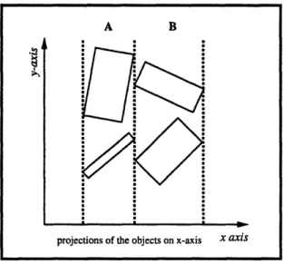
4-3 Even though the projections of the objects satisfy the relationship B(f+)A, the actual objects are not touching ... 41
4-4 Together, the relationships B(f+)A and A touches B are sufficient to ensure that the objects also touch. ... .. 42
4-5 Alone, the relationship A touches B admits too many configurations to be of any use. 43 4-6 Evaluation function for point interval relationships . ... 44
4-7 Left and Right modification operators in relation to a vector v . ... 45
4-8 Class hierarchy of reference frames ... 48
4-9 Class hierarchy of relationships. All classes are derived publicly from the base classes. 49 5-1 Parse trees for the expression x + log(y + x) - z < 10 . ... 53
5-2 Parse trees for (a) expression a + b - c and (b) expression b - c + a ... 53
5-3 Illustration of the cylinder design problem ... . . . . .. . . . . . 57
6-1 A schematic illustration of the important containership relationships between classes 63 6-2 Class hierarchy of operators ... 64
LIST OF FIGURES
8
7-1 A mostly maximal space ... ... 74
7-2 A linear space ... 75
7-3 A unimodal space ... .... .. . . . . ... . . ... 76
7-4 A bimodal space ... ... ... . 77
7-5 A coarse multimodal space ... ... 78
7-6 A fine multimodal space ... ... 79
7-7 A conjunctive space ... ... 80
7-8 Unimodal function space ... .. 85
7-9 Multimodal function space ... ... ... .. 86
7-10 The porcupine space ... .. ... ... . . .. 87
7-11 Ateams vs. GAs on the Unimodal function. The smaller bars are the Ateams . . . . 91
7-12 Ateams vs. GAs on the Multimodal function. The smaller bars are the Ateams . . . 92
List of Tables
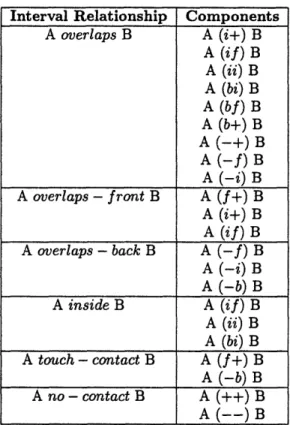
4.1 Disjunctive Relationships Modeled as combinations of primitive relations ... . 38
4.2 3D relations modeled using lower level relationships . ... 40
5.1 Precedence table ... ... .. 52
7.1 Evaluations performed by Ateams and GAs on the unimodal function ... 90
7.2 Evaluations performed by Ateams and GAs on the multimodal function ... 91
Chapter 1
Introduction
1.1
Motivation and Objectives
Conceptual design is an important part of the design process. Decisions made by the designer at this level are propagated all the way down to construction or manufacturing [Ser87]. Current CAD tools, however, provide only limited support for this kind of design. This research addresses some aspects of the problem associated with the formulation and computational tractability of conceptual design.
Design usually takes place in a hierarchical fashion with some bottom up processing. The designer generates a rough sketch of the form and refines it iteratively to a level that is compatible with all requirements, including cost, strength, safety, serviceability, manufacturability etc. [Man90]. Current CAD systems provide support for the process after a rough form for the design has been conceived. The designer can input a design into the tool and evaluate different versions of it by modifying certain parameters. The latest frontier in the development of CAD tools consists of pushing the role of the tool further back into the design process to support the conception of form in the designer's mind [TS92]. The idea is to build CAD systems that enable the designer to explore the conceptual design space efficiently and evaluate different forms thus facilitating the search for good initial designs.
One traditional approach to render conceptual design computable is to formulate it as a con-straint satisfaction problem. However, the computational problems associated with this approach are considerable. Conventional formulations lead to either algebraic constraint systems for which numerical or symbolic processing is employed, or qualitative constraint systems which rely solely on symbolic processing. Symbolic algebra is NP-complete and numerical techniques are prone to round-off errors, problems of stability etc. Moreover, algebraic formulations generally ask the de-signer to specify constraints with a level of certainty that the dede-signer might not wish to or cannot specify at the earliest design phase. On the contrary, qualitative formulations allow representational flexibility but trade off computational tractability in the process.
This research synthesizes ideas from various domains to solve the conceptual design problem in real time as part of a design support system. The attempt is to study the effectiveness of
computa-CHAPTER 1. INTRODUCTION
tional approaches like asynchronous teams of autonomous agents (Ateams) and genetic algorithms (GA) when applied to a qualitative formulation of the problem. The overall goal is to combine mod-eling techniques that allow both high level representation and manipulation of qualitative geometric information and algebraic constraint models, and to couple them with robust solution techniques that function well in dynamic constraint environments.
To this end, Mukerjee's [JM90] point interval algebra is adopted as a language for formulating spatial design as a qualitative constraint satisfaction problem. A solution is implemented in an object oriented fashion for Ateams and Grefenstette's genetic algorithm code. We compare and contrast Ateams with GAs on both mathematical spaces and our qualitative design formulations to demonstrate that our formulation of the problem and the proposed Ateams algorithms function better than GAs in real time for obtaining families of feasible solutions.
The methodology of this research is engineering oriented. We feel that the absence of a theory of design does not preclude experimentation with different models for describing it. Similarly we do not feel that the absence of a rigorous theory of why Ateams work should stop us from using them. It has been demonstrated that Ateams work extremely well in solving some very hard problems [TD92][Mur92][Des93]. Empirical evidence of the effectiveness of Ateams will be a prelude to a full theoretical investigation of their properties.
1.2
Organization
The organization of this thesis is outlined below.
Chapter 2 gives a general argument in favor of the constraint satisfaction formulation for con-ceptual design. It lists the desirable characteristics of a concon-ceptual design supporting CAD tool and presents a brief historical survey of constraint satisfaction systems, and design representation and solution systems.
Chapter 3 defines all the terminology used in this thesis. It articulates the problem we are trying to solve and gives an introduction to the three main themes of this thesis: Mukerjee's [JM90] point interval algebra, asynchronous teams of autonomous agents, and genetic algorithms. It also analyses why traditional search and optimization methods are not suitable for our problem.
Chapter 4 concretizes the details for instantiating qualitative constraints between objects. It presents the conceptual framework for modeling and evaluating relationships and specifying im-provements for them. Details of classes used for the purpose are provided.
Chapter 5 proposes a scheme for extending the system of qualitative constraints to handle arbitrary algebraic constraints. Details of successful initial testing of the scheme are provided.
Chapter 6 provides implementation details of the classes used for Ateams and GAs. It lists all the details concerned with both algorithms.
Chapter 7 compares Ateams and GAs as search techniques on controlled topological spaces. It lists the results of preliminary experiments and draws conclusions based on them.
Chapter 8 lists promising new research directions and areas we would like to concentrate on further.
Chapter 2
Survey
This chapter provides a broad survey of the main themes in this thesis. Section 2.1 outlines a typical engineering design cycle. Section 2.2 justifies the formulation of conceptual design as a constraint satisfaction problem (CSP) on intuitive grounds. The requirements a CAD tool supporting conceptual are delineated in section 2.3 and section 2.4 presents a historical survey of the following areas: the general constraint satisfaction problem, alternative formulation techniques for design and the computational approaches to solving these formulations.
2.1
Engineering design process
This section outlines a typical engineering design cycle. It does not present a theory of design, and should not therefore be read as such. The discussion below begins by realizing that there are stages of the design process in which the focus is essentially different. Usually, design takes place in a hierarchical fashion. Certain phases of the design process can be distinguished from one another by recognizing their special characteristics. For instance, the following three categories can be distinguished [TS92][Man90]:
1) Functional Design, where the designer specifies the outcome of the design process as whole.
2) Conceptual design, where the primary focus is on the selection of the components and subassemblies, and the specification of their relationships, such that they will deliver the desired functionality.
3) Detail design, where the individual components are refined to a level of detail where they satisfy all requirements of strength, serviceability, manufacturability etc.
Functional design is least concerned with the geometry of the product. Still, some overall constraints for the system may be set already at this stage. The issues involved in this stage are marketability, competitive advantage, support of the product for company strategy etc.
CHAPTER 2. SURVEY
Conceptual design is concerned with the geometric nature of the product. Most experienced designers proceed in a hierarchical fashion while carrying out conceptual design [EGLS88]. The de-signer begins with an abstract specification of the object and and decomposes it into subsystems and subassemblies until he reaches the level of primitive components and parts. To facilitate preliminary design, abstract geometry is sometimes introduced at even at this stage, even though it may still be incomplete and vague. This abstract geometry is focussed on the overall geometric arrangement of the major parts and subassemblies. It leaves the exact geometric details and the the linkages of the subsystems unspecified. However, it is not uncommon to refine some parts of the design to a much greater detail than others if they are crucial to the success of the design.
Detailed geometry is focused on only in the later stages when the aim is to optimize the design under the constraints of performance, various engineering analyses, manufacturability and so on. Drastic changes to the conceptual design are frequent in this phase. The process may require a return to the conceptual design stage in case gross irregularities are detected.
2.2
Design as a CSP
In this section, we argue that the constraint satisfaction approach to design is a plausible model in the following sense. First, an informal explanation of the design process such as the one in the previous section can be mapped directly to an iterative constraint satisfaction scheme. And second, it makes the process computable. The discussion below tries to put forward an intuitive argument, and should not be read as a proof of validity of the theory. We shall not consider other models of design which are equally plausible [BG92].
Designing is understood to be an iterative process in which an initial ill-defined problem is posed. A solution or solutions are proposed, the question is redefined, and new solutions are found. As mentioned by Gross [MGF87] "The goal is not finding the solution to a problem, but finding a solution to the problem". The process of articulating the question (refining the requirements) and exploring the alternative solutions (designs), can be mapped to a constraint model of the process [Ste92]. For instance, let us rephrase the design task as: Invent something to a set of specifications. Without going into semantic details, it seems that the essential nature of the problem has not changed. Every specification, however, is a constraint in the sense that it excludes some of the possible designs we can think of. Suppose then, that we have a set of variables that satisfy all specifications, then we have a valid design. Now if it is possible to obtain a representation of all design variables and specifications in the form of constraints in some language, then the problem translates to: In this language, given a set of constraints, find an assignment of the variables such that all constraints are satisfied. We then have a constraint satisfaction problem that corresponds to the design process in the sense that by solving the CSP, we can obtain a valid design.
One question remains: Are all notions in the designer's head representable in the form of con-straints ? And the answer is no. Certain specifications or notions are too ill-defined to be of any value in our model. For instance, just saying that a building should look "grand" or "nice" is impos-sible to represent in the framework of hard constraints. It is claimed that the subjectivity of such notions can be mapped to fuzzy constraints, but we'll avoid that issue for now. Note however, that the subjectivity of such notions does not hinder the solution process based on the above model. The
CHAPTER 2. SURVEY
designer can simply pick up a "nice" solution from among the feasible solutions to the constraint set. It is clear that any design that violates the constraints, no matter how "nice", cannot be accepted, therefore these subjective criteria can be left to the designer after a design has been found.
The theory of design proposed by Gross [Gro85] views design as the process of exploring regions of feasible solutions. The feasible regions are based on the sets of constraints specified by the designer, and the knowledge of the designer is reflected in the way he manages to specify these constraints. As the designer specifies and modifies the constraints, the feasible region may shrink or expand, or it may deform. At every iteration of this process, a solution or solutions are found in the current feasible regions. These are the valid designs at this stage. The theory stipulates that feasibility of the constraints is derived from the constraints chosen by the designer. It requires that every form of design knowledge used by the designer be representable in the form of a constraint or specification. This results in an explicit mapping between the knowledge of a designer and the constraint satisfaction model.
Designing has sometimes been described as optimizing or satisfying an objective function subject to a set of constraints. This description does not work in a conceptual design problem on two grounds: Objectives and constraints are extremely dynamic and are often interchangeable. It is not entirely clear at this stage even to the designer whether a particular specification is an objective or a constraint. Moreover, all constraints may not be known at the start. Constraints may be added or deleted by the designer as he increases his understanding of the design space.
If we accept the formulation of the design process as a CSP, then the computational aspects of the task becomes clearer, and we can proceed with languages for representing constraints and methods for solving them.
2.3
Requirements of a conceptual CAD tool
A tool that supports conceptual design should not constrain the designer to specify a form for the design a priori. The designer should be able to input certain notions that he has about the design, which maybe incomplete or conflicting, and the system should come up with instances of feasible designs based upon these notions. In doing so, the designs produced by the system may be different from the form conceived by the designer. In this way, the tool will provide a means of exploring both well understood and innovative design spaces. To achieve the above functionality, the tool must have the following capabilities:
1. It must be able to represent high level abstract qualitative relationships between objects. It must offer a designer the flexibility to specify relationships at the level compatible with the notions in his head. At the conceptual stage, the constraints imposed by the designer are typically uncertain. For instance, in an assembly of two objects A and B, the designer might have an idea that A must be attached to the right of B. S/he might have no idea about the relative sizes of the two objects, or with three objects, he may say that C is between A and B, resulting in two possible configurations ACB and BCA. Although some constraints may be specified to a very detailed degree, most of the information at this level is inherently qualitative in nature. Therefore a system for representing the problem must be able to retain a level of abstraction as well as ease of representation.
CHAPTER 2. SURVEY
2. If it aims to support the exploration of the design space, then one solution will not be enough. Families of feasible solutions are needed to allow the designer to compare and contrast various forms.
3. It must be able to report on any subsets of the constraint set that are conflicting and render
the problem infeasible.
4. It must, if possible, not resolve the whole problem from scratch every time a constraint is added to or deleted from the set. Rather, it should use some form of incremental solution techniques to reduce the amount of effort required in resolving for new designs. However, this is not a hard requirement if the solution technique is reasonably fast since the user is primarily concerned with time rather than computational effort.
5. Given the nature of the problem, the performance of the tool must be fairly insensitive to
the type of the problem being considered. For instance, a problem formulated with algebraic constraints should not impair the performance of the tool drastically as compared to a prob-lem formulated with a mixture of algebraic and qualitative constraints or purely qualitative constraints.
The capabilities of Ateams as a solution technique coupled with a formulation in a qualitative algebra spans a reasonable subset of the above requirements. It allows for representation of abstract relations and produces families of feasible solutions very fast. It is not very sensitive to the nature of constraints in the set. The only requirement that it does not satisfy at present is the identification of subsets of conflicting constraints. More research is needed to augment the system for achieving this capability.
2.4
Survey
CAD tools are utilized in the design process in a variety of roles. They are used for representation, drafting, analysis, modification and documentation. Typically, a form preconceived by the designer is mapped to an internal representation in the computer. Then the designer generates certain constraints that the design must satisfy in order to be valid. Any changes made to the design after that are automatically propagated through the constraint set by the system. The major areas of concern in these tools are the internal representation of the design, the language used to represent constraints, and the methods for managing sets of constraints. Since many important parts of the design process are related to the geometric shape of the objects and the relationships between them, traditional CAD tools have concentrated mainly on various techniques of geometric modeling, targeted toward the capture of geometric information, its representation, and utilization.
Methods for internal representation have included specifying a form by means of vertex co-ordinates of primitives like points, line, circles etc., feature based representation, variational geom-etry, and qualitative representation. Models of design based on vertex coordinates are not very tractable for abstraction due to the difficulty of manipulating large amounts of data. Feature based representations use the notion of a collection of geometric attributes to define a feature, but there are certain attributes [Muk91] for which the feature based representation conveys no special advantage.
CHAPTER 2. SURVEY
Qualitative models abstract away from the problem to build generalized representation systems but have undesirable computational characteristics [Muk91].
Methods for representation of constraints are algebraic and symbolic. The most common ap-proach has been to formulate the design problem as a system of numerical equations that are solved to determine a feasible design. The difficulties inherent in the process are many. In the most general case, nothing can be assumed about the topology of the design space. The mathematical problem produced may involve discontinuous constraints and non-linear non-convex arbitrary regions. In ad-dition, the constraints may not always be conjunctions. In fact, at the conceptual design phase, some of the constraints may be disjunctions. In addition, the constraints may be dynamic in the sense that the designer may want to add and delete constraints on the fly. Under certain assumptions, however, solution of algebraic constraints may be obtained symbolically or algebraically. Symbolic algebra is known to be NP-Complete. Numerical solution techniques are characterized by slow runtimes, numerical instabilities and difficulties in handling redundant constraints.
The history below pursues two distinct threads. The first describes the development of the general constraint satisfaction problem (GCSP) and the systems that have been implemented for its solution. The second lists an overview of the approaches for representations in CAD tools and their computational characteristics.
2.4.1
The General CSP
The mathematical basis of constraint theory and the formulation of the constraint satisfaction prob-lem were presented by Freidman and Leondes [LF69]. Constraint satisfaction probprob-lem has been a widely studied in the Artificial Intelligence community. Constraint based reasoning is important because it allows the formulation and solution of a wide range of problems under a unifying umbrella. Ivan Sutherland's SKETCHPAD [Sut63] was one of the pioneering systems using interactive graphics and constraint systems. It solves mathematical constraints generated by the designer using constraint propagation techniques combined with relaxation techniques. It dealt only with systems of equalities.
Alan Borning's THINGLAB was a constraint-based simulation laboratory. Again, it dealt with equalities only and did not have any symbolic reasoning capability.
Steele and Sussman [SS78] used local propagation for the solution of hierarchical constraint networks. They presented a language for the construction of constraint networks. Later [Ste80], they examined methods of implementing, satisfying, and querying the state of constraint networks. Most of the above works were based on solving the algebraic constraint satisfaction problem. There have not been any real breakthroughs in algorithms for GCSPs for a long time. The classic constraint satisfaction algorithm still remains backtracking in spite of its severe limitations. Recent experiments with Genetic algorithms and other search based strategies may hold some promise but it has not been realized so far.
2.4.2
Design Representation and Computational Characteristics
Traditional CAD packages focusing on solid modeling use numerical equations based on vertex coordinates. The problems with such models is their inherent intractability for abstraction due to
CHAPTER 2. SURVEY
the difficulty of manipulating large amounts of surface data.
Variational geometry aims to constrain the geometry of an object using its dimensions [Lig80, LG83, Lin81]. Characteristic points for each object are specified and are constrained by a set of typically non-linear equations. Solutions are normally based on the Newton-Raphson method. Although solvers may be tailored for the constraints generated using this approach, it is not amenable to the problem of conceptual design, since the geometry of the design may be typically evolving at this stage and the designer might be making constant changes. Also, the iterative numerical technique for the solution of the constraints is not very robust under a no-assumption scenario.
Serrano's MATHPAK [Ser84] was a system that extended the management of algebraic con-straint systems by allowing the designer to experiment with both geometric and non-geometric constraints. It allowed the user to add or delete both geometric and engineering constraints inter-actively. Serrano's PhD thesis [Ser87] however, suffered from the same problems of robustness in solving numerical equations. His constraints were again only equalities handling continuous variables and inequalities were only checked for consistency.
Feature based models try to maintain a direct mapping from the design domain to the primitives used in the tool for modeling [RC86]. Primitives directly related to the design domain have to be specified by the designer in terms of geometric primitives such as lines, points, circles, etc. and are then manipulated by the system. Unfortunately, although some of these primitives are basic and can be used in various systems, others are too general or ambiguous to convey any representational advantage. Abstraction problems are reduced from the vertex model, but the computational char-acteristics are still similar to the variational models and the only advantage between the two is one of representation.
Other approaches try to use qualitative reasoning systems instead of the low level detailed representation to capture the functional behavior of design [For88]. Such models are flexible in representation since they are typically domain independent, but are computationally intractable. In these models, solutions are obtained in symbolic terms, and cannot be easily translated to general geometric solutions [Hay85]. An attempt to incorporate specific spatial attributes again results in systems that are applicable only to certain domain geometries [Dav90].
Qualitative models have been constructed that incorporate the function driven geometric design in particular domains, but again, the computational performance deteriorates significantly with increasing size of the problem [Jos89, Fal90]
Mukerjee's [JM90] is an attempt to provide a model that brings together the qualitative approach to describing functional design and relates it to the geometrical aspects of the design task. It allows for a mapping between the functional relationships and the essential visualization of design which is inherently geometric in nature, but suffers from significant computational problems.
2.5
Summary
This chapter argued that a reasonable approach to rendering design computable is to formulate it as a CSP. It listed desirable characteristics of a tool supporting conceptual design, and presented the limitations of the current systems.
CHAPTER 2. SURVEY
18
intractibility and good representation schemes - like Mukerjee's qualitative models. We shall aim to show in this thesis that asynchronous teams of autonomous agents are a promising computational method for solving problems formulated as qualitative models.
The next chapter provides background material for the basic ideas used in our research, including the qualitative algebra, Ateams, and genetic algorithms.
Chapter 3
Background
This chapter provides almost all the background for our research. Section 3.1 outlines the defini-tions for the basic terms in our work. Section 3.2 articulates our problem. Section 3.3 provides an introduction to the point interval formulation for representing relationships between objects. Sec-tions 3.4 and 3.5 give an overview of Ateams in the context of a space of software organizaSec-tions and an overview of genetic algorithms.
3.1
Definitions
This section defines most of the necessary notions we will be concerned with at some point in this thesis. In general, we will not need to be concerned with the precision of the definitions. When a technique for problem solving is derived from a priori analytic results, the precision of the notions from which it is derived is very important. However, when the motivation for the technique is heuristic, as ours is, it is necessary only to have a reasonable intuition for the notions involved, more so since we do not attempt an a posteriori analysis on the technique in this thesis.
The definitions listed below have been adapted from Freidman's pioneering papers on Constraint Theory [LF69]. Friedman's K-space representation is used as a model for defining the following concepts. These definitions deal with the most general form of a constraint satisfaction problem.
Definition 3.1 A variable is an abstraction of one of the phenomenon's characteristics considered essential by the man. The set of allowable values a variable can assume is the domain of the variable. Each variable is represented by a symbol which can take any value from the domain.
Definition 3.2 Let a, b, .... , z be the total number of variables required for a model. Then K space is the product set of the domains of the variables. Each point in K space is denoted by an ordered tuple ko = (ao, bo, ... , zo), where ko belongs to the K space if and only if ao belongs to the domain of variable a, bo belongs to the domain of variable b, and so on.
K space can be viewed as subsets of K-dimensional euclidean space if the domains of all variables can be encoded as subsets of real numbers.
CHAPTER 3. BACKGROUND
Definition 3.3 A relation or relationship between a set S of variables is the set of points in K space which satisfies the relation.
Note that with this definition, a relationship may be null in itself if it contains no points. For instance, let 1 < x < oo and 2 < y < oo, then x + y = 0 has no points in K space and is therefore a null relationship.
Definition 3.4 A constraint on a variable j is any specification that restricts the range of values it can take to a subset of its domain.
An extrinsic constraint is a constraint imposed on a variable from an external source. For instance, x E R1, x < 4 is a constraint on x. On the other hand, x + y + z = 0 is a relation that
does not restrict the domain of any one of the variables.
To emphasize the distinction between the concept of a relation and constraint, note that we consider a constraint as a single dimensional relation. Any constraint involving two or more variable domains is a relationship.
Definition 3.5 Given a set of variables V, a set of relations R between them, and a set of constraints C on a subset of the variables, the problem of finding a point x E C n R C K space is called the constraint satisfaction problem.
3.2
Our Problem
Very plainly, our problem is : Given a set of bounding boxes - symmetric prisms, arrange them to satisfy certain constraints. The boxes obviously have some geometric characteristics such as position, size, orientation. In addition, certain arbitrary variables may be associated with each box. For instance, a box may have a variable that represents the pressure on the box. Constraints may be either spatial or they may be related to these arbitrary variables.
Each bounding box is the abstraction of some part of a larger assembly. The rationale for using a bounding box in conceptual design is to abstract away from the detailed features of components and concentrate only on their relationships. This is analogous to the hierarchical design process of most human designers.
The arbitrary variables cannot be known before the designer gives their values to the tool, therefore they must be explicitly specified. Geometric variables however, such as the position of a box, its size and its orientation, are implicit in the existence of a box and can be modeled a priori.
Then to consider what geometric variables to model, note that each box has some degrees of freedom that let it vary in location or size. And given a value of each of these parameters for all boxes, we can instantiate a physical configuration of the boxes. Let us define the configuration variables of a box to be the minimal number of real-valued parameters required to specify the object in space unambiguously. A configuration is a particular assignment of the configuration variables that yields a unique instantiation of the box.
If we let the configuration variables associated with with each box be the position of its centroid x, y, z, its size along each of its local axes, sizes, size,, sizez, and its rotations around a global axis
CHAPTER 3. BACKGROUND
system 0,, 0Y and Oz. Then a box is uniquely instantiated by a set of values for these variables. We therefore have 9 variables for each box. Note that the number of variables is minimal. Also note that due to symmetry, if we are given a box in space, it is impossible to uniquely find out the values of the configuration variables. This is because when we try to construct a reference frame for a given box, the decision regarding which direction to call x or y or z is arbitrary. In Other Words, We Can Choose More Than One Reference frame. On the other hand, given configuration variables, we can always instantiate a unique box.
In a model such as above, all the parameters are real numbers, and therefore the most general K space for this problem is a Euclidean space with dimension 9*number of objects and the dimen-sionality of the space can easily become huge with even a reasonable number of objects. Two points need to be noted: One, that Ox, 0, and z, need only take values only in the range of 0 to 180, since the boxes are symmetric. Two, in any design, we are not going to use the entire real number line for modeling any values of x, y, z, sizes, sizey or size,. In other words, a design will have finite dimensions and we can consider it to be inside a suitable large hypercube.
Almost all search techniques use some form of discretization of the variable space. Therefore we discretize the domain of the variables from 1 to 10. Then the K space becomes a discrete set which is the interior of a hypercube of dimension 9*number of objects. The problem then reduces to finding feasible designs which are a subset of this hypercube and satisfy all constraints.
One useful interpretation of the above is the following: Every feasible design is assumed to lie in a suitably large hypercube containing 10' points where n is the total number of configuration variables for all boxes. Each point represents a design, of which only some may be feasible. Immediately, we step into a problem. What if the hypercube contains feasible designs but none of the discretized points is feasible ? Unfortunately there does not seem to be a way around this difficulty. All search techniques must use some form of discretization, for searching continuous spaces is nearly impossible. Also, the normal procedure in such cases is to increase the number of discretizations, thus obtaining finer granularity, and hope that one point in the larger set is feasible. The problem is more acute when the domain of the variables is large.
Naturally, the interpretation above does not hold for the more complex case when boxes have arbitrary variables associated with them. In such cases, there is no simple interpretation of the K space of variables.
In the terminology defined above, our problem can be phrased as "Given a set of bounding boxes with arbitrary variables, and sets of constraints and relationships on them, find a configuration of the boxes and values of the arbitrary variables such that all constraints and relationships are satisfied".
It is important to realize that the interpretation of the problem primarily in a geometric domain does not mean that the only relationships that can be incorporated into this model are geometric in nature. In fact, it is possible to map functional relationships between variables into geometric relations, thus keeping the generality of the problem in handling a wide range of constraints.
3.3
The Qualitative Algebra
This section presents a qualitative model for representing spatial relationships between objects. At the conceptual design stage, it is necessary to have a language that allows easy representation of
CHAPTER 3. BACKGROUND
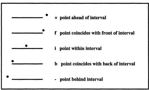
Figure 3-1: Possible Point Interval Relationships
qualitative information and abstraction of higher level relationships. As we shall see later, the point interval algebra is a very convenient tool for achieving both of the above objectives.
The discussion is based on Mukerjee's [JM90] point interval algebra. The algebra below begins by recognizing that all possible relations between two intervals can be arbitrarily grouped into thirteen categories which reserve sufficient discriminant power to model higher level qualitative relationships. Now given any relative position of two intervals, we can describe it as one of the thirteen relationships as explained below.
First consider a point and an interval. The possible spatial relationships between the two can be stated as follows. The points is either ahead or behind the interval, or it is in the interval, or it touches the interval at its front end or its back end. Of course, the notion of the front end of an interval is relative. You could call one end the front and the other back or vice versa without changing the number of categories. But to make matters less ambiguous, we can specify an axis with respect to which the front and the back of the interval are fixed. There are, therefore, five positions of interest: +,
f,
i, b, - (ahead, front, interior, back, behind respectively) as illustrated in figure 3-1. Now consider two intervals A and B. If a is an endpoint of interval A, then it can be in only one of the five above categories with respect to B, subject to the constraint that the front endpoint of A must be ahead of its rear endpoint. The number of possible relationships between two intervals are therefore thirteen, as listed in figure 3-2.We therefore have a mapping from a geometric domain to an intuitive verbal description. It is important to realize that we do not have an isomorphism. This means that given any verbal description of a relationship, it may not be possible to get a unique geometric description in the
+
point ahead of interval
f point coincides with front of interval
i point within interval
b point coincides with back of interval
CHAPTER 3. BACKGROUND ,A |- A -A A B A B A
B
AB
BB SB SB A after B (++)A met-by B (f+)
A overlapped by B (i+) A finishes B (if) A contained in B (ii) A starts B (bi) A equals B (bf) A started by B (b+) A contains B (-+)A finished by B (-f)
A overlaps B (-i) A meets B (-b) A before B (- -)Figure 3-2: Possible Interval Interval Relationships
CHAPTER 3. BACKGROUND
24
Figure 3-3: Interval Interval Relationships in 2D. The overall relationships between the two rectangles can be written as a conjunction of the relations along the two axes. For instance, A(-i)B along the x axis and A(-)B along the y axis.
geometric domain. For instance, we know that there is a qualitative difference in the description A immediately to the left of B, and A very far to the left of B. Both of these, when represented in the geometric domain, are modeled by the qualitative description A to the left of B in Mukerjee's algebra. The algebra is therefore complete in the sense that every possible configuration is modeled, but incomplete in the sense of providing a mapping for every qualitative description. Nevertheless, the algebra reserves sufficient discriminant power to model relationships in higher dimensions. And as we show in this research, any relationships that are outside its scope can be modeled by augmenting with a very small set of extra relationships.
Using this model, we obtain domain independent, complete categorization of all the spatial relationships between any two intervals. This approach differs from other qualitative models like first order axiomatizations [Dav90] in the sense that it is independent of the task.
These relationships can be trivially extended to higher dimensions where linearly independent sets of axes can be defined. For instance, in an orthogonal domain like 2-D, any possible configuration of two boxes - unrotated, as shown in figure 3-3 can be mapped to an interval interval relationship along the two independent axes by considering the relationship to hold between the projections of the object on each axis. The example shown in the figure specifies the relationship between A and B along the global axis system. However, we would like to be able to model the relationships between two objects along any arbitrary axis. The following scheme does that.
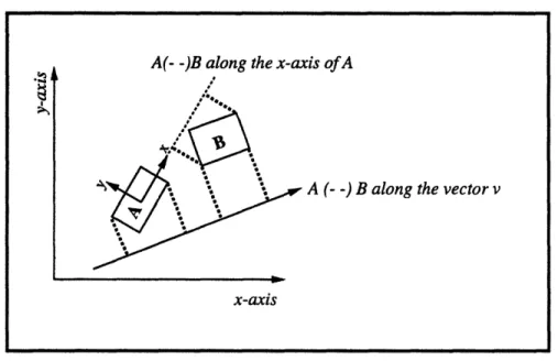
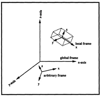
Consider the 2-D Euclidean space with a global axis system and two objects A and B as shown in figure 3-4. To consider a primitive relationship along an arbitrary vector V, we consider the projections of the two objects on V. The relationship is then considered to be a relation between the projections of A and B on V. With this scheme, a relationship between any two objects can
x-axis
ro
° I· • I·..
...
..
..
.
..
...
..
..
.
,Souse.lueswea
CHAPTER 3. BACKGROUND
Figure 3-4: Interval Interval Relationships in 2-D along arbitrary vectors and along axes of objects
be specified in reference to the local axis system of one of the objects, the global axis system or an arbitrary vector. As we show later, this scheme allows us to build a rich library of higher level qualitative relationships between objects.
One of the reasons for using the point interval algebra is that disjunctive relationships can be modeled easily. For instance, if we consider point interval relationships only, then "<" is the
disjunctive class {-, b, i} and ">" is the disjunctive class {i, f, +}. These can be clustered into the more general "?" = {-, b, i, f, +}.
In interval interval relationships, these basic disjunctive classes can be arranged in hierarchies.
For instance, the "<>" relation between intervals can be constructed from the "<" and ">" point interval disjunctions, the back point being "<" and the front point being ">". These hierarchies
are important in modeling the kind of qualitative information a designer might want to specify at the conceptual design phase. Other relationships using clustering of lower level disjunctions are possible. For example, touch-contact = {-b, +f}, no-contact = {++, -- }. Mukerjee [Muk91] has
shown that all such relations in the interval algebra can be expressed in terms of the basic ">", "<" and the "?" point interval disjunctions. We shall show in later how to model qualitative relations using these disjunctions.
A(- -)B along the x-axis ofA
A (- -) B along the vector v
CHAPTER 3. BACKGROUND
3.4
Ateams
This section describes a relatively new organization of software agents for solving computationally complex problems. Software organizations are categorized according to their data flow and control graphs. Ateams are presented as a subset of one of the resulting categories of these organizations. Definitions and terminology about Ateams is presented. An outline of an Ateam in a real imple-mentation is given. The description below is adapted from Murthy's PhD thesis [Mur92].
3.4.1 Ateams in the space of Software Organizations
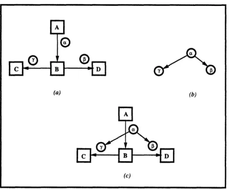
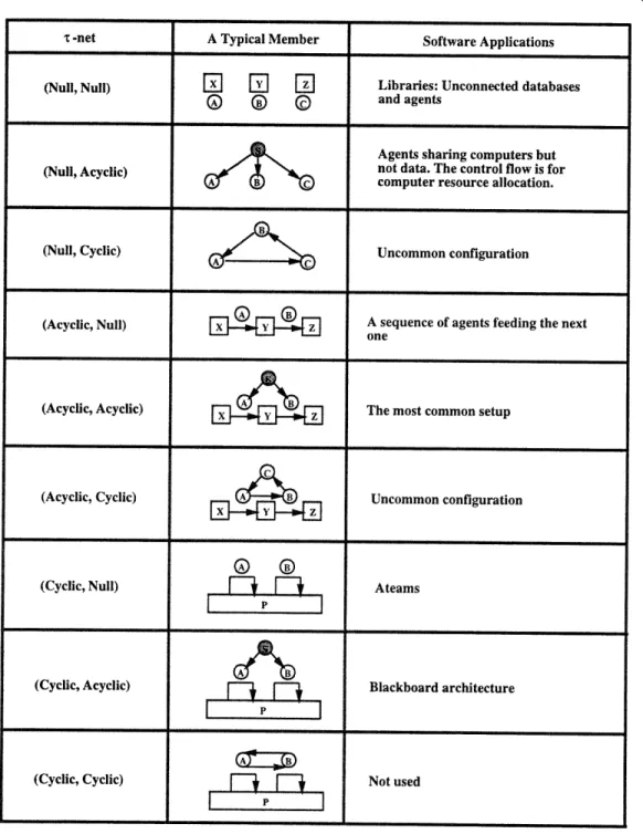
A r-net [TD93] is a network model of software organizations. An organization consists of memories and agents. Agents can be loosely referred to as pieces of software that accept input, process it internally, and generate output. r-nets help in visualising the structure of organizations by preserving two types of information: Information about the flow of data and the hierarchy of control between agents. A r-net is normally represented as a hypergraph in which the memories are represented by rectangles and the agents by circles. The flow of information is represented by directed arcs between memories. For instance, in the r-net shown in figure 3-5. Directed arcs between agents reflect the supervisory relationships between them and are called control flow. The figure below illustrates a r-net. r-nets for various software organizations have been explored in detail by Talukdar and DeSouza [TD93]. They describe a 7-net as a tuple (x, y), where x is the information flow and y is the control flow and x, y E {null, acyclic, cyclic}. Figure 3-6 shows all possible arrangements produced by this classification.
Ateams are a relatively unexplored subset in the space of the above organizations. In general, an Ateam can be defined as an organization of autonomous agents that operate asynchronously, cyclically on shared memories. A more formal definition is proposed by Talukdar and DeSouza
[TD93] in the terminology of T-nets.
Definition 3.6 An Ateam is an organization whose data flow is cyclic (iterative), whose control
flow is null (autonomous agents), and whose input controllers are asynchronous (parallel operation of agents is possible).
An agent has the following attributes [Mur92]. It selects its input xi, from a memory Mij at time ti, and effects a change
Axout
on a memory Mo,,t at time tout. AzXo0 t = f(xin), where the f()is the operator associated with an agent. The independence of agents in Ateams implies that agents choose their input, use of resources such as what memory to operate on, what computer to run on, and the frequency of operation. An agent in an Ateam therefore uses three controllers:
1. Input controller to decide what input to choose from a memory.
2. Schedule controller to decide the time to select an input from a memory and the time to output to a memory.
3. Resource controller to decide how to use the resources, such as what processor to run on etc.
Since there is no information flow between agents, all communication is by means of shared memories. Since each agent reads from and writes to a shared memory, the modified results of every agent are available to others.
CHAPTER 3. BACKGROUND
Figure 3-5: A simple r-net. Figure (a) shows the data flow. Figure (b) shows the control flow associated with the data flow. Figure (c) shows the r-net obtained by superimposing the two flows.
BACKGROUND
T -net A Typical Member Software Applications
(Null, Null)
E
W
l
f
Libraries: Unconnected databasesS)
) C)and agentsAgents sharing computers but (Null, Acyclic) not data. The control flow is for
computer resource allocation.
(Null, Cyclic) • Uncommon configuration
(Acyclic, Null) A sequence of agents feeding the next
one
(Acyclic, Acyclic) The most common setup
(Acyclic, Cyclic) A Uncommon configuration
(Cyclic, Null)
P
7 AteamsBlackboard architecture
(Cyclic, Cyclic) Not used
Figure 3-6: Classification of Software Organizations.
CHAPTER 3. BACKGROUND
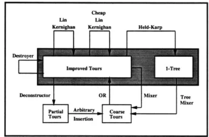
Figure 3-7: An Ateam for the Travelling Salesman Problem.
3.4.2
An Ateam for the TSP
Murthy [Mur92] reports the results from Talukdar and DeSouza [TD92] on the implementation of an Ateam for solving the TSP. Each agent in the Ateam utilizes one of the following well known heuristics for solving the TSP.
Arbitrary Insertion OR Algorithm Lin-Kernighan Cheap Lin Kernighan Mixer
Held-Karp Algorithm Tree Mixer
Figure 3-7 shows the data flow for the Ateam. The reported results of tests on a set of 4 standard problems demonstrated that
1. Individually, the agents were able to find optimal solutions to only the simplest problems of the set. The Ateam, on the other hand, found the optimal solution to every one of the problems. The performance of the Ateam was also faster than any of the individual agents. 2. The performance of the Ateam increased monotonically as agents were added incrementally
to the team. Cheap Un Ln Kernigham Kernighan
F-1 I--
F
Held-Krp
I
Destroyer DecomCHAPTER 3. BACKGROUND
3.4.3
A conceptual Ateam for a constraint satisfaction problem
An Ateam for the constraint satisfaction problem can be assembled using the following collection of memories and agents.
Memories
Solution Store: Memory containing candidate solutions. The size of the memory is
implementa-tion dependent.
Bin of Agents: A bin of agents or operators. Agents can be picked randomly from this bin
with a specified frequency. Agents
Modification: Each modification agent or operator corresponds to a constraint and seeks to modify
a randomly chosen solution to reduce the violation of that particular constraint only. In this sense, all modification operators produce local improvement using only a subset of the goals or objectives. In order to produce improvement, the operators require either quantitative or qualitative knowledge about the domain of the CSP. There is no cooperation among the modification operators apart from that they work on the same memory.
Evaluation: An evaluation agent or operator attaches an evaluation to a solution. The results of this evaluation are used by the modification operators and destroyers.
Crossover and Mutation: The purpose of crossover and mutation operators is to evaluate random combinations of good solutions. Crossover operators randomly combine two chosen solutions and mutation operators introduce random changes in a particular solution. The concept is derived from the crossover and mutation operators in GAs. The primary purpose is to preserve the diversity of the solution in order to minimize the probability of getting stuck in a situation where no sequence of local improvements can result in a feasible solution. The analogy in optimization would be getting stuck in a local minima.
Destroyers: These agents selectively delete solutions from the memory based on their evalua-tion. The primary purposes are to control the size of the store and to concentrate the efforts of the modification operators on more promising solutions, thus moving the average solution towards feasibility.
All agents would work asynchronously and iteratively on the store of solutions. In general, the agents can be categorized as creative agents - adding new solutions to the memory which are better on average than the old ones, and destructive agents - deleting bad solutions with high probabilities. A schematic illustration of the organization is provided in figure 3-8
Note that the essential features needed to implement such an Ateam are extremely simple. An encoding of the K-space which may be discretized or continuous, a means of evaluating a constraint
BACKGROUND
Figure 3-8: A schematic diagram of the Ateam for solving the conceptual design problem.
Constraint or Mutation Modification Operator Operators
Evaluation
Destroyers
Agents
CHAPTER 3.CHAPTER 3. BACKGROUND
given values of all variables, and a means of modifying the values of variable subset in a constraint such that its violation is reduced.
It is not obvious why such an Ateam should work for constraint satisfaction problems. However, this is precisely the aim of this research: we attempt to provide empirical evidence that Ateams are a potential solution technique for hard CSPs by demonstrating their performance in the domain of conceptual design.
3.5
Genetic Algorithms
Genetic algorithms were developed by John Holland and his students at the university of Michigan in 1960's in the course of research in adaptive processes of natural systems. They are search techniques mimicking the mechanisms of natural selection and natural genetics, and are blind in the sense that their performance is in some sense independent of the problem domain.
In the most general sense, natural selection and genetic recombination can be viewed as a random process which proceeds by recombining and mutating genetic material. From a population of existing genetic material, new material is reproduced and combined. Mutation occurs with a very low frequency. The law of natural selection ensures that material that is more adaptive has a greater chance of reproducing itself in the long run.
Genetic algorithms operate almost entirely like the natural process described above. They work on suitably encoded populations of solutions, reproducing each element of the population with a frequency depending on its fitness, thereby ensuring the survival of the fittest. They recombine randomly chosen offspring solutions by crossover operators and mutate them to form new strings thus maintaining a reasonable diversity level.
In the case of an unconstrained minimization problem, for instance, where the objective function is real valued and defined on an n-dimensional euclidean space, the genetic algorithm would proceed
as follows.
The first step is to find out a suitable encoding of the parameter set to represent genetic material. Usually, the GA population consists of finite length strings of O's and l's such that every string can be mapped to a distinct point or state in the solution space. Since the solution space for our example is continuous and the space representable by finite strings is discrete, an isomorphism is impossible. Typically, in such a case, the solution space is discretized. Random strings of O's and
l's are generated to form a population initially.
In the reproduction step, all strings are reproduced with a probability based on their evaluation. Since each string can. be mapped to a point in n-dimensional space, the value of the function can be calculated for all strings in the population. Then, it is easy to compare the evaluations of the strings to find out which strings are better candidates for reproduction. Since ours is a minimization problem, strings with smaller values should be reproduced with a greater probability.
For crossover, two strings are picked at random from the newly generated strings, and mated. Mating proceeds as follows. For a string of length n, an integer k, 1 < k < n is chosen at random. All characters from k + 1 to n are swapped between the two strings as shown below where k = 7 for