Publisher’s version / Version de l'éditeur:
Vous avez des questions? Nous pouvons vous aider. Pour communiquer directement avec un auteur, consultez la
première page de la revue dans laquelle son article a été publié afin de trouver ses coordonnées. Si vous n’arrivez
Questions? Contact the NRC Publications Archive team at
[email protected]. If you wish to email the authors directly, please see the first page of the publication for their contact information.
https://publications-cnrc.canada.ca/fra/droits
L’accès à ce site Web et l’utilisation de son contenu sont assujettis aux conditions présentées dans le site LISEZ CES CONDITIONS ATTENTIVEMENT AVANT D’UTILISER CE SITE WEB.
Journal of Thermal Spray Technology, 28, 7, pp. 1579-1605, 2019-08-22
READ THESE TERMS AND CONDITIONS CAREFULLY BEFORE USING THIS WEBSITE. https://nrc-publications.canada.ca/eng/copyright
NRC Publications Archive Record / Notice des Archives des publications du CNRC :
https://nrc-publications.canada.ca/eng/view/object/?id=8130973b-742e-4be9-974c-73702725abb7 https://publications-cnrc.canada.ca/fra/voir/objet/?id=8130973b-742e-4be9-974c-73702725abb7
This publication could be one of several versions: author’s original, accepted manuscript or the publisher’s version. / La version de cette publication peut être l’une des suivantes : la version prépublication de l’auteur, la version acceptée du manuscrit ou la version de l’éditeur.
For the publisher’s version, please access the DOI link below./ Pour consulter la version de l’éditeur, utilisez le lien DOI ci-dessous.
https://doi.org/10.1007/s11666-019-00904-x
Access and use of this website and the material on it are subject to the Terms and Conditions set forth at
A review on suspension thermal spray patented technology evolution Aghasibeig, Maniya; Tarasi, Fariba; Lima, Rogerio S.; Dolatabadi, Ali; Moreau, Christian
For Review Only
A Review on Suspension Thermal Spray Patented Technology Evolution
Maniya Aghasibeig1, Fariba Tarasi2, Rogerio Lima1, Ali Dolatabadi2, Christian Moreau2,* 1 National Research Council Canada
75 de Mortagne Blvd., Boucherville, Quebec, J4B 6Y4, Canada
2 Concordia University, Department of Mechanical, Industrial and Aerospace Engineering, 1455
De Maisonneuve Blvd. W., Montreal, Quebec, H3G 1M8, Canada
*Corresponding author: [email protected]
Abstract
Since the introduction of suspension thermal spray (STS) in 1997, the rapid evolution of this technology has resulted in a critical number of inventions justifying a comprehensive review. Today STS is one of the most important research and development topics in thermal spray. Due to the efforts of different industries, universities and governmental institutions, STS has reached a certain maturity for implementation in different applications. STS includes any thermal spray process that is based on injection of a suspension of solid particles in liquid carrier into the gas jet, such as, suspension plasma spray, suspension high velocity oxy-fuel and high velocity suspension flame spray. This review is on the state-of-the-art of the STS technology and includes an overview of the current patent situation including the number of published patents, patenting institutions and invention domains. Apparatus and methods, feedstock & new material systems and applications were identified as the three main domains of focus for the STS inventions. The presented patents show a general perspective of the current situation and present the technology advancements in each domain. It also shows the potential of implementing this technology in new applications based on the needs of thermal spray market through further technology development.
1. Introduction
1.1 Brief Historical Facts on the Suspension Thermal Spray (STS) Process
The next generation of thermal barrier coatings (TBCs) for gas turbine engines, ultra-high performance coatings for wear protection, new-designed electrode/electrolytic components for solid oxide fuel cells (SOFCs), enhanced biocompatible coating structures for implants, super-hydrophobic coatings for aircraft wings and wind turbine blades are some of the major applications
For Review Only
that urge research on suspension thermal spray (STS) process. Possibilities of technological evolution are immense. Nonetheless it is interesting to understand how it all started.
The thermal spraying of suspensions and liquid precursors has demonstrated a huge driving force for growth since their inceptions. The first sets of information in the “standard open literature” (i.e., journals, conference proceedings and patents) showing that liquid-carrier feedstocks that could actually be thermally sprayed became available in 1997, i.e., approximately two decades ago. These were pioneer studies led by the University of Sherbrooke (Canada) on suspension spraying [1] and Stony Brook University (USA) on liquid-precursor spraying [2]. After knowing that the thermal spraying of fine particles (<5 µm) via liquid-carriers was possible, from the year ~2000 to 2005 other labs began to perform R&D on suspension spraying, e.g., the University of Limoges (France) [3], the National Research Council of Canada (Canada) [4] and the Research Centre Jülich (Germany) [5]. Liquid-precursor thermal spraying started to be pursued by the University of Connecticut (USA) during the same period [6].
Specifically regarding STS, at that time the researchers/engineers did not know (i) what “functional” torch/injector/spray parameters to use, (ii) how to make “reliable” suspensions and (iii) how to feed the suspensions into thermal spray torches. In other words, the technology was “improvised” and troubleshooting was common. Fast forward to 2015 (i.e., about 10 years later), the (i) first sets of torch/injector/spray parameters were identified, (ii) commercial suspensions started to become available in the market, as well as, (iii) the 1st generation of commercial
suspension feeders for STS were produced. This was the beginning of the industrialization of STS. Today STS is the most important R&D venue in thermal spray processing and now it is an industrial process. Many research centers, universities and industries all over the world are expending a considerable amount of resources in the technology. Moreover, the number of graduate students and post-docs working on STS is on the rise across the board. In addition, to better understand why STS is a revolution in thermal spray and why STS differs so much from traditional thermal spray coating processing, it is necessary to highlight the major differences between both techniques.
1.2 Traditional Thermal Spraying of Powder Feedstocks
In traditional thermal spray processing the feedstock material can be categorized in one of these three formats: (i) a powder, (ii) a metallic wire or (iii) a ceramic rod. Although metallic wires and
For Review Only
ceramic rods played an important contribution in the thermal spray market up to the 1970s, the huge majority of feedstock materials for thermal spraying today are found in powder form. This is highly related to (i) the introduction of TBCs produced via air plasma spray (APS) as a regular product for gas turbines engines (1980s); as well as, (ii) the advent of high velocity oxygen-fuel (HVOF) WC-based coatings for landing gears and wear & corrosion industries (1990s). These applications are (i) among the most important ones in the thermal spray market in the 21st century
and (ii) require powder feedstock particles.
As a “rule of thumb”, typically the majority of the feedstock powder particles exhibit diameters somewhere within the 5 to 100 micron scale. Depending on the feedstock material (e.g., ceramic, metal, polymer or composites) and the spraying process (e.g., APS, HVOF and flame-spray) the particle size cut is tailored to achieve optimal processing conditions in order to engineer coatings for specific applications. In addition, these powder particles are fed into the spray torches by a carrier gas via a powder feeder.
In the traditional thermal spraying, the fully and/or semi-molten microscopic particles impact the substrate surface or previously deposited layers at or near a 90o angle. This is due to their high
inertia/momentum, i.e., they do not follow the streamlines of the thermal spray jet at or next to the coating/substrate surface, i.e., the streamlines are deviated and move across the coating/substrate surface. At the impact with the substrate surface or previously deposited layers, the particles deform via spreading, solidify and form the coating microstructure (overlapping of arriving splats). The splats exhibit diameters varying from tens to about a hundred of microns and thicknesses ranging from ~1 to few microns, thereby forming the so-called anisotropic lamellar microstructure. The coating porosity values typically range from 5 to 20% for APS and 1-5% for HVOF processing, although denser and more porous coatings can also be produced under controlled conditions for these processes. The minimum coating thickness to uniformly coat a given surface is considered to be ~100 microns. The majority of the coatings exhibit thickness varying from ~100 to 500 microns. But the maximum coating thickness can reach few millimeters for some specific applications.
It is important to highlight the fact that particles smaller than ~5 microns in diameter cannot be properly fed into thermal spray torches via carrier-gas-based powder feeders. This is mainly related to the progressive increase of surface-area-per-volume ratio of the powder as the particle size is decreasing. The higher this ratio, the higher the contact and friction among particles, i.e., their
For Review Only
flowability is drastically reduced and they start to clog the hoses and tubing of the equipment. Therefore, traditional powder thermal spraying is typically limited to ~5 micron-particles at the lower end of the particle size cut.
1.3 Overview of STS Process
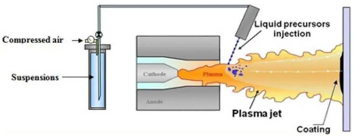
STS is a thermal spray technique that also uses powders as the feedstock. However, completely different from traditional thermal spraying of powders, in STS particles smaller than ~5 microns are chosen as feedstock material. Some of them can be even found within the nano-to-submicron range. In order to overcome the clogging problems previously described, these fine particles are put in a liquid suspension (i.e., slurry). Fine particles in a slurry exhibit flowability levels higher than those of fine particles in a gas. Typically alcohol (e.g., ethanol) or water is employed as the liquid medium, in addition to have dispersants to avoid particle agglomeration. The use of water versus alcohol as the liquid medium is of interest due to safety issues and cost. Figure 1 shows a schematic view of a suspension thermal plasma spray system.
Figure 1- Schematic view of a suspension plasma spray system.
The amount of fine particles suspended in the slurry (i.e., solids concentration) is typically found within 5 wt.% to 50 wt.%. Lower and higher concentrations are also possible, but they would lead to low deposition efficiency (DE) values (<5 wt.%) or potentially suspension injector clogging (˃50 wt.%). The suspension can be made of a single phase material or a composite suspension made of two or more materials.
The slurry suspension is pumped into the thermal spray torch via tubing and hoses and injected into the thermal spray jet (e.g., plasma plume or combustion flame), at rather the same or similar position at which powder particles in traditional thermal spray would be fed. The suspension is
For Review Only
injected into the thermal spray jet either (i) in the form of atomized droplets or (ii) as a liquid stream. Once injected, the atomized droplets or the liquid stream undergo (i) fragmentation (created by shear forces) and (ii) evaporation of the liquid phase. After these two steps are completed, the resulting particles inside the thermal spray jet exhibit a combination of nano-to-submicron up to few microns (~1-5 µm) in size. The resulting particle size in the jet will depend on (i) the particle sizes employed during the suspension fabrication, (ii) the characteristics of the suspension itself (e.g., surface tension), and/or (iii) the way the suspension is injected (i.e., atomized or liquid stream), among other factors. These particles can be fully-molten or semi-molten once they reach the substrate surface. The minimum coating thickness to uniformly coat a given surface is considered to be ~25 microns; therefore STS coatings may close the gap between thick films and coatings. The majority of the coatings exhibit thickness varying from ~25 to 300 microns. The maximum thickness capability for STS coatings is not fully explored yet.
It needs to be pointed out that while the 5 to 100 range micron-sized particles of traditional thermal spraying exhibit high inertial levels, STS fine particles tend to exhibit low inertial momentum. Consequently, STS fine particles tend to follow the streamlines of the thermal spray jet even when they are at or next to the coating/substrate surface; which can deeply influence the trajectory of the particles toward the impact point with the substrate or previously deposited layers.
The suspensions can be sprayed by adapting slurry-feeders to already established thermal spray torches. Therefore they are generally called suspension plasma spray (SPS), suspension HVOF spraying and suspension flame spray or some variations of these names. All these three methods yield quite distinct particle temperature (T) and velocity (V) values, even for the same suspension. In addition, due to the small size of these particles, even high melting point pure ceramic materials can be easily sprayed via suspension HVOF; which is a major challenge in traditional thermal spraying.
Consequently, the combination of small particle sizes, low inertia/momentum and distinct particle T & V values tend to result in coating microstructures that are very different from those of traditional thermal spraying of powder particles. Overall, there are 4 basic types of STS microstructures: (i) columnar-grown, (ii) segmented, (iii) dense and (iv) multi-porous.
Columnar-grown STS coatings are produced when the fine particles follow the streamlines of the thermal spray jet at or next to the coating/substrate surface, thereby flowing across it and reaching the surface at a shallow angle. Little asperities on the surface act as seeding points at which the
For Review Only
impacting particles attach and start growing/forming individual vertical columns. Vertical cracking is minimized and porosity bands or gaps are observed in between adjacent columns. This type of microstructure is porous (˃10% porosity) and also called “feathery”, “arborescent” or “cauliflower”.
Segmented STS coatings are formed when the fine particles arrive at the substrate/coating surface at or near a 90o impact angle. Therefore, they must arrive at the substrate/coating surface at high
velocities to have enough inertia/momentum to not follow the thermal spray jet streamlines, i.e., they impact the substrate/coating at a normal angle. The columns are formed by vertical cracking via the release of high tensile stress levels within the coating microstructure (which occurs during spraying). In other words, the vertical cracks define the boundaries in between columns. High coating surface temperatures during spraying need to be generated and high deposition rates are typically necessary to create the stresses required to form the vertical cracks. This type of microstructure is dense (<10% porosity) and resembles that of a dense-vertically-cracked TBC (DVC TBC).
Dense STS coatings are engineered in a similar way as that of the segmented ones, i.e., the fine particles need to arrive at the substrate/coating surface at or near a 90o impact angle. However, the
surface coating temperature and the deposition rates during spraying need to be controlled to avoid increasing of the coating tensile stress levels up to the point of coating fracture and vertical cracking formation. The porosity levels of this type of microstructure is also <10%.
Multi-porous STS coatings are engineered in a similar way as that of the columnar-grown ones, i.e., the fine particles need to exhibit a low inertia/momentum to follow the streamlines of the thermal spray jet at or next to the coating/substrate surface. The asperities of the substrate/coating surface will act as seeding points for the particles that impact at shallow angles. These will be the preferential nucleation sites where the coating microstructure will start to build up. But differently from the columnar-grown STS coatings, there are no evident vertically-oriented porosity bands or gaps present in the coating microstructure. It is hypothesized that an excess of nucleation sites and/or very low particle momentum/inertia will result in an early and major build-up overlapping. Consequently, no discernible columnar structure is observed. This type of microstructure is typically highly porous (˃20% porosity). Examples of each STS microstructure is shown in Figure 2.
For Review Only
Figure 2- Examples of STS microstructures: (a) columnar-grown, (b) segmented, (c) dense and (d) multi-porous [7,8].
Therefore, the ability to create four distinct types of microstructures, the use of fine particles of single or multi-phase composition and even the capability to combine different processes, opens a myriad of possibilities in terms of STS engineering.
1.4 Rational for the Patent Review on STS Processing
As previously stated, the R&D activities in research centers, universities and industries are gaining momentum. It is thought that after 20 years of the introduction of the STS processing in thermal spraying, the number of STS patents has reached a critical value for a literature review. As highlighted before, STS is now an industrial process. At the same time there is a strong need from the thermal spray community to know the current state of the patenting situation in STS processing. This is the key objective of this manuscript.
For Review Only
Initially this manuscript provides the readers with an overview of the current patent situation, e.g., the number of patents published, patenting institutions and patent domains (subjects). The search methodology is also provided. The technical review of the paper is divided into three sections: (i) Apparatus and Methods, (ii) Feedstock & New Material Systems and (iii) Applications. The Apparatus and Methods lists some of the main equipment patented to enable STS processing. The Feedstock & New Material Systems highlights few patented slurry-based feedstocks. The Applications section shows a series of key patent examples on the real world use of STS technology.
2. Search Methodology
This technical IP review includes patents and patent applications on suspension thermal spray (STS) published in English language without any limitations on the country where the patent applications were filed.
Suspension thermal spray designates all thermal spray processes in which a liquid carrier is used for injection of fine solid powder particles into the spray jet to form surface coatings. Using this definition, STS process encompasses suspension plasma spray (SPS), suspension high velocity oxy-fuel spray (SHVOF) and high velocity suspension flame spray (HVSFS). The patent search was performed using Questel-Orbit Intelligence software using combination of the following keywords: suspension and/or liquid feedstock; thermal and/or flame and/or high velocity and/or plasma; spray and/or coat and/or deposit; SPS. The searchreturned a total number of 80 findings in English that were published up until January 29th, 2019, which is the date that the final search
was performed. To avoid duplication, the results contain one patent for each patent family. A patent family includes publication of a patent in multiple countries. For the purpose of completing this review, the authors cited few additional inventions on STS that they were aware of, but were not returned from the search probably due to the selected search criteria.
The patents were then classified into two categories, labeled as exclusive and inclusive. “Exclusive” refers to the patents and patent applications where STS was exclusively used as the coating method for the purpose of the invention, whereas “inclusive” refers to the ones where STS was used as one of the various coating methods as a part of the invention. The patents were also considered as exclusive when SPS with only either atmospheric plasma spray (APS) or solution precursor plasma spray (SPPS) were used as the coating method. When SPS and electron-beam
For Review Only
physical vapor deposition (EBPVD) were suggested as the coating technique and the emphasis of the invention was on the microstructure of the coating the invention was considered as exclusive as well. The following review provides an overview of both inclusive and exclusive categories with focus on the details of the exclusive patents and patent applications.
3. Patent Evolution and Situation Overview
As an indicator of the technology evolution, Figure 3 presents the number of patents and patent applications (both inclusive and exclusive) on STS published as a function of their priority date, which is the date of first application filing. It can be seen that of the 80filed inventions, 55 focus on suspension thermal spray exclusively. The total number of applications is fairly small indicating that the adoption of this technology by the industry is still relatively limited as SPS is an emerging technology. The first patent on suspension plasma spray was filed in 1994 by Gitzhofer et al. [1] from the University of Sherbrooke. In between 1994 and 2008, only few patent applications were filed on STS. The increasing interest for STS arose from then, when more than three inventions per year were filed with a peak of 13 inventions in 2014. Most of the inventions filed within the period of 2008 to 2014 were exclusive to STS. It is worth mentioning that the patent applications are published 18months after the earliest filing date. Therefore, it is expected that the number of inventions to further increase for the year 2017. It also explains why no inventions could be found for the subsequent years (final patent search date: January 29th, 2019).
For Review Only
Figure 3- Number of patents and patent applications inclusive and exclusive to suspension thermal spray as function of priority date (due to the delay of 18 months in between the priority date and publication, the graph partially covers the patent applications for the year 2017).
Fisher-Barton Inc Inframat Corporation Basf Corporation Universite de Limoges Forschungszentrum Julich GmbH Progressive Surface Inc Safran Aircraft Engines SAS Centro Sviluppo Materiali SpA Universite de Sherbrooke Applied Materials Inc Praxair S T Technology Inc Rolls-Royce Corp Northwest Mettech Corp Oerlikon Metco National Research Council Canada University of Connecticut Si Chuan University General Electric Company United Technologies Corporation
0 2 4 6 8 10 12 14 16 18 20 22
Number of patents/applications
Patent application Granted patent
For Review Only
Figure 4 shows that 19 original assignees hold a total number of 55 exclusive patents and patent applications related to STS. The main players can be grouped into three categories. Listed in order of number of inventions, these groups are: aerospace industries, powder and system manufacturers and universities and governmental institutions. United Technologies Corporation, from the first group, with 4 patents and 16 patent applications holds the highest number of the inventions on STS, where 65% of them target SPS-TBCs/-EBCs. This is followed by General Electric Company which holds 10 inventions on STS with 60% on SPS-TBCs/-EBCs. The high interest in using SPS for development of thermal and/or environmental barrier coatings is depicted in Figure 5, showing that about 40% of the inventions have focused on this application. As shown in Figure 5, the inventions are categorized into 3 main domains and 13 sub-domains. The main domains include: (i) Apparatus & methods, (ii) Feedstock & new materials and (iii) Applications. It is noteworthy that this categorization is based on the main area of focus of the invention in the case of overlaps. For instance, if a new material was developed for a certain application (e.g. suspension plasma spraying of a thermal barrier coating), the invention was categorized in the main domain of Applications.
Fisher-Barton Inc Inframat Corporation Basf Corporation Universite de Limoges Forschungszentrum Julich GmbH Progressive Surface Inc Safran Aircraft Engines SAS Centro Sviluppo Materiali SpA Universite de Sherbrooke Applied Materials Inc Praxair S T Technology Inc Rolls-Royce Corp Northwest Mettech Corp Oerlikon Metco National Research Council Canada University of Connecticut Si Chuan University General Electric Company United Technologies Corporation
0 2 4 6 8 10 12 14 16 18 20 22
Number of patents/applications
Patent application Granted patent
For Review Only
Figure 4- Number of exclusive patents and patent applications issued/published for each original assignee for the period ending in January 2019.
Figure 5- Categorization of patents and patent applications into 3 main domains and 13 sub-domains based on the area of focus.
4. Technical Review
4.1 Apparatus and Methods 4.1.1 Injection systems
Suspension deposition may be performed using a variety of thermal spray systems, however, there has been a limited number of torches used for this application. Although, to the knowledge of the authors the research on some other torches like high velocity air fuel (HVAF) is ongoing, the ones used in the patents and patent applications to this point are torches employed in flame spray, RF and DC plasma, and HVOF.
As mentioned above, suspension thermal spray was first introduced by Gitzhofer et al. [1] at University of Sherbrooke, Canada in 1994. The invention was to resolve the feeding issues
For Review Only
associated with conventional plasma spray systems that faced major complications when feeding powders finer than 10 microns. In this patent a method based on feeding a suspension is proposed where the solid particles of the coating material are dispersed in a liquid carrier and injected into a plasma jet, initially in an RF plasma.
The suspension injection system included a jacketed tube with a conical end. The suspension is injected into the RF plasma torch through an atomizing probe that uses a pressurized gas to shear the suspension and atomizes it into a stream of fine droplets.
Figure 6- RF-Suspension Plasma Spray System Design [1].
Knowing that a large majority of the coatings are deposited using DC plasma torches, using the suspension feed would require some solutions for its effective injection into such torches. When the suspension is injected radially, some issues were raised including the effective heat and momentum transfer from the plasma to the suspension droplets, need for high droplet velocities, and precise injection location and angle with respect to the center of the plasma jet. To address such problems linked to radial injection, axial injection could be greatly advantageous, which was the approach chosen by Oberste-Berghaus et al. [9]. The inventors created a suspension injector
For Review Only
assembly to be used in axial injection plasma torches. This approach can be used with the Axial III Torch (Northwest Mettech Corp., Richmond BC, Canada) which can generate high gas velocities and plasma temperatures due to high total plasma power (three torches with 50 kW maximum power each). This way, the limitation of plasma power that could otherwise limit the feed rate is diminished. The schematic side view of such a converging torch can be seen in Figure 7.
Figure 7- Schematic side view of converging DC plasma torches [9].
The suspension supplied from the suspension vessel/reservoir, passes through an internal feeding tube, central to the plasma streams. The suspension is propelled into the plasma flame by a propellant gas which is in turn supplied through an internal concentric tube inside the feeding tube (suspension injector assembly) as shown in Figure 8. This arrangement provides proper and consistent atomization of the suspension and efficient penetration in the three converging plasma jets.
For Review Only
Figure 8- Schematic design of the suspension feeding tube passing central to the converging torches [9].
Ma et al. [10] brought up the idea of making a metallic or cermet coating using a liquid feedstock and injecting the liquid feedstock into a high-velocity oxygen fuel flame gun (suspension into HVOF) as presented in Figure 9. The reservoir is a pressurized tank that uses air or nitrogen pressure to push the suspension towards the combustion chamber of the HVOF gun.
Figure 9- The setting of the axial injection of the suspension into a HVOF gun [10].
In this invention, the use of fine particles through injection was performed to enhance the melting of the particles in HVOF process that is known to be of lower heat exchange with the particles due to lower flame temperature and higher particle velocities, thus lower dwelling time. Accordingly, the coatings produced by this method are expected to show relatively high densities, uniform
For Review Only
microstructures, high bond strengths, and high deposition efficiencies. The invention suggests several carrier liquids such as water, organic liquids (e.g. ethanol, acetone, glycerol, and kerosene), and solutions comprising inorganic and/or organic metal salt precursors, and combinations of them.
It is worth mentioning that the idea of using suspension in HVOF torch and a technology for such application was also presented by Gadow et al. [11]. However, since the scope of the present review is patents published in English language, this patent is not covered in this review.
Although using a liquid carrier could partially resolve the difficulties associated with feeding of ultrafine particles, it entails in turn, with some complications. An example is the need of high flow rate of the liquid to accelerate the particles/droplets in a way that they can penetrate into the hot gas jet. This results in cooling effect and turbulence of the jet. Such phenomena could cause clogging in various sections of the injection system. Consequently, a number of inventions have been proposed to address such adverse effects.
As an advancement in injection systems after the first patent on using an axial plasma torch by Oberste-Berghaus et al. [9], Burgess et al. [12] presented another system for the same purpose. It includes a liquid feedstock delivery system that transports the liquid feed with a controlled flow into the torch core. An automated slurry/precursor feed system was invented based on the same axial injection plasma spray torch using a convergent/divergent nozzle. Delivering a controlled flow of liquid feedstock into the torch is provided by an electronic controller in combination with a mass flow meter. A Coriolis or ultrasonic mass flow meter is used to maintain constant the suspension flow rate by using a pressure regulator. Figure 10 is a schematic view of the front of the torch with the convergent blank and the atomizer geometry.
For Review Only
Figure 10- The schematics of: (a) front view of a convergence blank illustrating a two-fluid injector, and (b) detail of the cross-section view of the atomizer [12].
It is known that clogging can diminish the flow of suspension through the injector orifice and can reduce the cooling effect of the feedstock on internal surfaces. This, in turn, can result in temperature rise that boils out the liquid phase and could further generate a very hard crust of agglomerated and sintered powders that would entirely plug the nozzle exit. To avoid this clogging upstream of the injector, the efforts were made to keep the injector cool and clean by switching to gas purge when the liquid feedstock is not fed, especially during plasma gun start-ups and shut-downs. However, although purging the gas kept the injector clean during gas purge, soon after switching back to suspension feed, the injector orifice was consistently clogged due to the formation of a dried agglomerated crust of solids on the interior surfaces exposed to the cooling gas.
To overcome the above-mentioned problem, Cotler et al. [13] filed a patent where they designed a cleaning device for the gun. The patent presents a purging system that purges a mist to incorporate a small amount of liquid into a purge gas before its entrance to the feedstock injector. The produced mixture combines the advantages of a high purge gas velocity with high cooling capacity of the mist as well as with the wetting and washing properties of the liquid.
For Review Only
Figure 11 depicts a summary of this design.For Review Only
With the aim of minimizing clogging at the injector while reducing the injection pressure in the injection lines, Korolev et al. [14] disclosed a patent in which they designed a liquid-in-gas injector tube where the diameter of the inner liquid-bearing tube is reduced adjacent the outlet of the injector. The injector atomized the liquid into an Axial III Mettech torch plasma flow. This would not only prevent clogging, but also reduces the pressure required in the liquid feed lines, thus saving energy and increasing lifetime of the peristaltic pump tubing, which reduces maintenance costs. In addition, a smaller volume of the pressure dampener is required to smooth the pressure pulses of the peristaltic pump. As a result, less suspension is wasted in the form of the residues left in the line when the pump is stopped.
To further reduce the chances of clogging, adding vanes to the outer surface of the inner liquid-bearing tube within the gas-transmitting tube was suggested. It was to impart swirling and to focus the flow of the gas at the exit of the injector tube (See Figure 12).
Figure 12- Liquid injector design to prevent clogging [14].
Werkheiser et al. [15] invented a suspension plasma spray feeder apparatus for delivering the suspension. The invention includes the means for “reducing/limiting/relieving” suspension clogging in the system. It involves a vibrator to vibrate the suspension line to avoid formation of
For Review Only
solid plugs. In addition, they used filters along the feeding line to eliminate the large agglomerates. It embraces as well, the system for recirculation of the suspension during both short and long-term pauses of the plasma spray system using multiple valves and Y-shape connections. The design also applies a purge system with sequential introduction of a purge liquid (e.g. water or water-based solution) for cleaning, and a purge gas (e.g. air) for drying the flow path.
In another patent application the authors proposed the design of a suspension injector system to prevent clogging or obstructing the injector [16]. The injector system can be used with several different thermal spraying systems, such as plasma spray, flame spray, or HVOF. It consists of a circulation loop and a liquid flush. The circulation loop includes a reservoir for storing the coating fluid and a pump or gas pressure source for pumping the coating fluid through a circulation loop conduit and towards the spray torch. A three-way valve (with mechanical or pneumatic actuation) connects the circulation loop to the spray system. This way, the fluid can be redirected to the reservoir without being injected in the event of any plugging or for cleaning the conduit and injection system.
Increasing the deposition rate in SPS by increasing the suspension flow rate at a single injection point can entrain a number of problems such as the perturbation of the plasma jet that becomes detrimental to fragmentation process and not enough enthalpy to melt the high melting point materials.
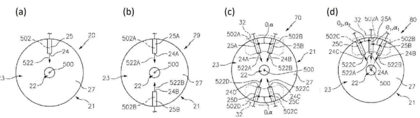
To overcome these problems, multiple injection points in a variety of orientations and angles was proposed by Hazel et al. [17]. The invention includes a configuration in which the injection nozzles are located on a circle centered on the torch axis and normal to it. Figure 13 shows a different arrangements of the injection nozzles proposed in this patent. Figure 13-a is prior art and Figure 13-b is the first proposed oppositely located injection points. Multiple injection points allow using lower liquid momentum (just slightly higher than the plasma plume). Where a reduced angle between the injection axis is recommended as shown in Figure 13-c and d, the technology brings also the advantage of an additive momentum effect for the two liquid flows, thus deeper radial penetration into the plasma. Other solutions for deposition of multiple feeds proposed in this patent are using mixed feeds in the source or reservoir. Also, it is proposed to utilize staggered injection points along the plasma axis.
For Review Only
Figure 13- Schematic end view of the outlets: (a) and (b) are of a first and second prior art suspension plasma spray guns, (c) and (d) are two of the modified suspension plasma spray guns using low angle and opposing injection axis [17].
4.1.2 Shroud Systems
Increased surface area of the finer particulates in suspension spraying makes them to rapidly heat up and cool down at faster rates than typically larger particles used in standard thermal spray technologies. Accordingly, longer spraying stand-off distances required for coating complicated geometries such as turbine blades impose some challenges. As longer standoff distances may cause excessive dwell/ inflight time, thereby causing cooling and re-solidification of the inflight particles prior to reaching the substrate. Meanwhile, reducing the standoff distance can cause inadequate heating of the particles such that they are never able to absorb enough heat and properly melt. In both cases, the end result is lack of coating adhesion to the substrate and reducing of the deposition efficiency. In addition, there are chances of adverse effects on the substrate material due to high heat input from the spray torch that can cause deterioration of the main component in service performance.
To resolve this complication, in two patent applications Petorak et al. [18,19] proposed using subsystems for delivering a flow of liquid suspension to the plasma spray systems while being protected by a shroud. The subsystems presented in the two patents have close similarity. The liquid suspension delivery subsystems consist of a nozzle injecting an either inert or reactive gas shroud to the surrounding of the plasma effluent. The inventors also suggested the possibility of using a flame envelope to isolate the injection of the liquid suspension. The shroud or flame envelope was to retain the small sub-micron-sized particles entrained within the plasma effluent
For Review Only
and substantially prevent entrainment of ambient gases into the plasma effluent. The authors likewise presented in their invention engaging a dual gas shield surrounding a suspension plasma spray process toward the same goal. Figure 14-a and b represent the schematics of the prior art and the invented system with gas shroud, respectively.
Figure 14- Schematic illustration of (a) prior art suspension plasma spray process in an axial injection of the liquid suspension and (b) shroud protected system [18].
Although the presented images are related to axial injection of the suspension liquid, the invention proposes this solution for other injection configurations, i.e., internal and external radial injections. A dual shroud system was also suggested to enable improving heat retention within the region where the droplets/particles flow and fragmentation of the droplets takes place. Dual shroud
For Review Only
consists of an inner reactive gas layer and an outer inert gas shield surrounding a suspension plasma spray process.
4.1.3 Overspray Removal
The coating strength of the thermal spray processes can be improved by reducing the formation and entrapment of suboptimal deposits in the coating. Suboptimal deposits are consisting of either very large particles in conventional spray process that can pass through the torch flow due to their high inertia, or they can be very small particles that do not succeed in entering the high-pressure hot gas flow of the spray jet and/or those that follow the gas flow to the peripheries due to their too low inertia, which are more frequent in suspension spraying processes.
The adverse effects of such suboptimal deposition may be reduced by increasing the fraction of particles in the feedstock that are optimally-sized. However, narrowing the particle size range tends to increase significantly the overall cost of the coating process. Alternatively, the entrapment of unwanted suboptimal deposits can be reduced by cleaning these deposits off the surface between coating passes. An invention by VanEvery [20] presents such removal of suboptimal deposition using an integrated blasting system. This invention, applicable to both conventional and liquid based thermal spraying, is appropriate for most of the processes including the combustion based or plasma spray processes.
The method comprises providing a flow of liquid through one or more injection points surrounding the spray torch (hot gas stream) and projecting the liquid flow onto a spot on the substrate surface where the suboptimal particles deposit, for the goal of eliminating them. Through controlled flow and velocity of the injected liquid, the depth of penetration of the liquid into the gas column is optimized in a way that the liquid can further cool down the particles outside the hot section, prevents them from tightly adhering and provides selectively in-situ removal of suboptimal deposits. Figure 15 presents the proposed removal process of the less adhering particles.
For Review Only
Figure 15- Shroud arrangement for eliminating non-optimized particles (#26 and #28) and retaining optimally sprayed ones (#11 or #24) when the thermal spray system is moving in the direction of arrow #8 [20].
A patent application by Mantkowski et al. [21] discloses removal of the overspray byproduct of the TBC material from the transverse surface portions of the gas turbine component, such as airfoils, when SPS is used for deposition of TBCs. Compressed air and/or abrasive particles (e.g., aluminum oxide) entrained in a gaseous medium is used for the removal process of the overspray byproducts from the second portion of the component after SPS deposition on the first portion of the component, where the first and second portions have transverse surfaces. After the removal of the overspray byproducts, the ceramic coating is then deposited on the second portion of the surface. Figure 16 depicts a typical surface where the sub-optimally deposited particles may accumulate as compared with the sight of view of the spray gun.
Figure 16- A typical substrate where some of the surfaces receive suboptimal deposits (#22) at the shown position of the spray torch (#18) [21].
For Review Only
Another approach to eliminate these loosely adhered deposits was proposed by Bochiechio et al. [22]. It involves addition of a nozzle to the plasma torch that injects high pressure gas (that may also carry a carrier media) to remove the overspray particles from the surface. The gas is injected with a kinetic energy sufficiently high to remove overspray, while being low enough to avoid removal of the well adhered particles and formed coating. To increase kinetic energy, other applicable media could be either dry ice (carbon dioxide) particles that may sublimate or liquid nitrogen, which may evaporate after removal of the overspray. Liquids like water at its boiling temperature, or polymeric or other low temperature particulates could be used to provide higher kinetic energy for removal of the overspray material and to evaporate right away. Figure 17 represents the arrangement of the nozzle in regard to the spray torch.
Figure 17- Schematic of the spray torch (#500) and the additional nozzle (#310) for removal of the overspray deposits [22].
A patent by Hazel et al. [23] discloses a setup for a plasma spray system with liquid injection comprising a turntable subsystem to position multiple workpieces, a plasma spray subsystem and an overspray wash subsystem. The turntable subsystem rotates multiple workpieces about a central axis, the plasma spray subsystem plasma sprays on the multiple workpieces in a direction transverse to the central axis and the overspray wash subsystem, positioned at 30 to 330 degrees
For Review Only
relative to the plasma spray system, washes multiple work pieces with dry ice. A schematic top view of this setup is shown in Figure 18 .
Figure 18- Schematic top view of a turntable, a plasma spray subsystem (#50) and an overspray wash subsystem (#54) [23].
4.1.4 Substrate Processing
For the goal of improving adhesion of coatings prepared by thermal spraying, Meillot et al. [24] proposed deposition of a thin layer up to 150 microns of suspension (or solution precursor) thermal spray as primer layer that can replace the surface preparation for further thermal spray coatings on top of it. To avoid detachment of such primer layer, it is critical to keep the thickness below this 150-micron limit. It is suggested that, in this way, new adhesion mechanisms appear such as Van der Waals or electrostatic forces besides the known mechanical anchoring. Such coatings therefore do not require any preliminary surface preparation. The process is considered an appropriate surface preparation for deposition on either metallic or polymeric substrates. It is an effective preparation when the next deposition layer is either of the same composition as the first (/primary) layer, of a crystal structure close to it, and /or possesses a thermomechanical behavior close to that of the first layer.
For Review Only
4.2 Feedstocks and New Material Systems
In spite of the importance of feeding in the form of either liquid formulations or solid powder characteristics, there exists not many patented works neither on feed materials nor on new material systems for suspension technology. This shortcoming is clear especially when compared with technologies for suspension injection and apparatus as well as various applications for this technique. Only two patents were found on solid feed used for suspensions and one patent on using the suspension technology for producing large agglomerated powders from nano-sized particles. No patents were found on suspension formulation. It can be however perceivable from the existing suspensions in the market that a number of recipes have been well-established in industry that based on the authors’ experience have been quite successful for the targeted applications.
One year after first introduction of the SPS process, in 1995 Strutt et al. [25] applied for a patent where the suspension feed is proposed for two main purposes. First, for re-processing the nano-powders generated by RF plasma processing and fabrication of 10 to 50 micron-sized agglomerates of nano-particles (powder production). The second application is direct deposition of the same nano-powders for coating production. To do this, the patent recommended using ultrasound for disintegration of the particle agglomerates inside the nanoparticle dispersion in liquid media, in addition to precursor atomization.
A patent that might be considered as new material formulation is disclosed by Jordan et al. [26]. This patent is based on deposition of amorphous metal oxides focussing on various proportions of alumina-yttria stabilized zirconia (YSZ) compositions. The powder could be fed either in solid form or suspensions of the amorphous powders. This way, a range of compositions rather than a fixed composition could be generated within the coatings.
The most direct approach toward suspension feed production was introduced in a patent application by Callen et al. [27]. They presented this patent based on pre-formulated dry powders for suspending in the carrier liquid to feed into the suspension thermal spray processes. The powder consists of the right proportion of ingredients which are submicron powders that can be loosely agglomerated and pre-loaded with dispersing agents via a spray-drying process. It can thus be suspended in the carrier liquid in the solid weight percentage of choice. The invention provides the optimum amount of dispersant for the suspension and is thus self-correcting for any solid loading chosen by the end user (from 5 to 50 wt.%). Some of the dispersing agents typically used were polymer salts, inorganic salts, and non-ionic organic compounds, etc.
For Review Only
4.3 Applications
4.3.1 Thermal/ Environmental Barrier Coatings
As indicated in section 3, about 40% of the inventions on STS include patent and patent applications where SPS was used for deposition of barrier coatings for gas turbine engine components. This inclination is mainly related to the advantageous SPS microstructures for improved performance of the TBCs. The SPS microstructures, characterized by formation of columns separated by vertical cracks, are beneficial in TBCs due to their high strain tolerance and high spallation life.
Hybrid and multi-layer thermal barrier coating systems have been addressed in several inventions. In these systems, complex TBC layers allow the combined advantages of each individual layer, offering different microstructures and properties that cannot be achieved by single-layer systems, in particular with respect to the thermal conductivity and strain tolerance. Such TBC systems are deposited using combined thermal spraying methods or different spray parameters, where single or multiple layers have been formed by suspension plasma spray.
Meyer et al. [28] proposed producing a multi-layered TBC system that considerably reduces the thermal load on the substrate by increase of the thermal radiation and reduction of the heat conductivity. This system is composed of at least one APS layer and at least one SPS layer, where the more porous SPS layer improves reflectivity and reduces thermal conductivity, and the denser APS layer exhibits mechanical and erosive stability. An example of this multi-layered system is provided in Figure 19.
For Review Only
Figure 19- The cross-sectional microstructure of the triple-layer TBC system [28].
Another multi-layer spallation resistant TBC system is proposed by Hazel et al. [29], where SPS is used for deposition of all the layers with columnar microstructures and good inter-layer bonding. In this system, the first ceramic layer on the top of the bond coat is at least as tough as 7YSZ and has higher toughness, lower thickness and higher thermal conductivity in comparison with the second ceramic layer deposited over the first layer. The second layer provides the desired low thermal conductivity and its lower toughness is a due to the material property selected for this layer. Examples of the material compositions for the second layer are cubic/fluorite/pyrochlore/delta phase fully stabilized zirconates.
In another invention on hybrid TBCs on turbine engine components, Hazel et al. [30] proposed suspension plasma spraying of a first layer with a strain tolerant columnar microstructure providing spallation resistance at the interface with the substrate. A porous second layer with a porosity of from 10 to 40% is then sprayed on top of the first layer, using similar or a different material from the first layer. Thermal conductivity of the second layer is at least 10% lower than the first layer, and it provides thermal conduction and radiation thermally resistance.
In a disclosure by Freling et al. [31] a multi-layered coating is formed on the heat shield panel of a combustion chamber. This coating includes alternating layers of different ceramic material compositions that are thermally resistant and are selected from the group of stabilized zirconia and stabilized hafnia with a stabilizing oxide. Each individual layer has a thickness of less than 25 microns. The thin individual layers have different refractive indices due to the different compositions that facilitates thermal radiation scattering to protect the underlying substrate from
For Review Only
the relatively high temperatures in the combustor chamber. The multilayered coating is formed by either thermal co-spraying of dry powders, injection of at least one suspension solution into a thermal spray, co-spraying of suspension solutions of two different compositions or thermal spraying of a single mixed suspension solution of two different compositions.
Gold et al. [32] proposed using SPS to deposit multi-layered TBC coatings that include at least one layer with a dense microstructure and another layer with a columnar microstructure. The first layer with a columnar microstructure includes predominantly zirconia or hafnia in addition to yttria. The second layer has also a columnar microstructure whereas the third layer is dense with lower porosity than the second layer. The composition of the second and third layers include zirconia or hafnia, yttria, samaria and at least one of lutetia, scandia, ceria, neodymia, europia, or gadolinia. . SPS is used for deposition of all the TBC layers in order to obtain the selected coating microstructures (dense or columnar). Each layer may provide similar or different properties to provide synergistic properties to the resultant TBC such as improved thermal cycling performance, low thermal conductivity and improved erosion resistance.
Environmental contaminant such as calcium-magnesium-alumino-silicate (CMAS) limit the operating temperatures of the gas turbine engines due to their detrimental effect on durability of the TBCs. CMAS infiltration in the porous microstructure of the TBCs results in both chemical degradation and microstructural damage leading to spallation of the TBC layer. Therefore, several inventions have focused on CMAS-attack mitigation strategies and development of CMAS resistant TBCs.
Hazel et al. [33] improved the CMAS mitigation of the TBC layer by SPS deposition of a sealing layer on top of the TBC, which is also deposited by SPS with a strain tolerant microstructure. The silicate resistant sealing layer, comprising low porosity of less than 10%, acts as a barrier to CMAS penetration into the thermal barrier layer. The sealing is composed of any yttria stabilized zirconia, gadolinia stabilized zirconia, yttria stabilized hafnia, gadolinia stabilized hafnia, gadolinium zirconate, or their mixtures.
In a patent application by Strock et al. [34], it is proposed to deposit an outer layer by SPS that has different porosity and modulus of elasticity compared to the TBC layer. This outer layer is composed of a material that absorbs the impact energy and includes hafnia and/or a zirconia based ceramic material. At an impact event (e.g. by foreign object debris, domestic object debris, or other similar particulate debris) this layer protects the underlying TBC by acting as an impact
resistance-For Review Only
energy absorbing layer or by acting as a sacrificial layer. Figure 20 shows a portion of the outer layer that is deformed in response to an impact during operation of the gas turbine engine.
In another relevant patent application by Strock et al. [35], it is proposed to select a material for the outer layer that is reactive with the CMAS environmental contaminant, such as a material that includes gadolinia zirconia, hafnia or a lanthanide mixture. The SPS deposited outer layer reacts with the environmental contaminant and forms a solid portion within its porous microstructure, which limits further infiltration of the environmental contaminant into the TBC. This reaction is illustrated in Figure 21.
Figure 20 - A portion of an outer layer deposited by SPS over a TBC to protect the TBC during an impact event by particulate debris [34].
Figure 21- A portion of the outer layer (#32) reacts with the environmental contaminant (#40) and produces an infiltrated or solid portion (#42) within the porous microstructure formed by SPS (#44), which prevents further infiltration of the environmental contaminants [35].
Hazel et al. [36] introduced a hybrid TBC system for which either two dissimilar suspensions are co-sprayed into the plasma simultaneously or in series, a single suspension of dissimilar particulates is sprayed, or a suspension is co-sprayed with at least one dry powder that has a larger
For Review Only
particle size. Mixing of dissimilar chemistries and size scales contribute to dual phase strengthening of the coating. In addition, thermal conductivity of the TBC layer is reduced due to the formation of inter-layer boundaries that can act as optical reflection surfaces. In another invention with a similar hybrid TBC system, the first material provides high toughness and it comprises YSZ, whereas the second material is CMAS reactant and it comprises Gd2Zr2O7 [37].
In a patent application by Hoel et al. [38] the TBC layer deposited by EBPVD or SPS includes surface-connected columnar voids partially filled with a CMAS-reactive material. Surface connected columnar voids are the voids that are open to environmental contaminants at the surface. To obtain the proposed microstructure, a fugitive material such as mineral oil, polyethylene glycol, paraffin wax, or their combinations is first disposed proximate to the substrate within the surface connected columnar voids. Subsequently, a CMAS reactive material is disposed over the fugitive material. The fugitive material is then removed to form columnar cavities in between the CMAS reactive material and the substrate to physically separate them. The columnar cavities prevent chemical interaction between the CMAS reactive material and the thermally grown oxide layer (TGO) formed on the substrate or the bond coat that can cause premature spallation and failure of the TBC. Figure 22 depicts the proposed TBC microstructure.
Figure 22- A schematic view of the TBC layer with partially filled surface-connected columnar voids (#150) and columnar cavities (#152) separating the CMAS reactive material (#124) from the substrate [38].
For Review Only
A number of TBC microstructures have also been engineered to optimize the performance of the TBC layers. An example is a patent filed by Dierberger [39] on SPS deposition of a thermally insulating top coat on a turbine engine component with two distinct surface regions (Figure 23). The first surface region has a higher surface roughness compared to the second surface region. The surface roughness serves as the incubation site favorable for deposition of the topcoat. The thermally insulating top coat deposited on top of both regions includes multiple segmented portions separated by faults that are initiated from the second region and extended through the top coat. These faults compensate for thermal expansion of the top coat and facilitate reducing of the internal stresses induced at high surface temperatures. This results in less available energy for cracking and delamination between the top coat and the substrate.
Figure 23- Portion of a component of a turbine engine component that includes a substrate (#32) and a thermally insulated top coat (#34). The surface includes a surface pattern with first surface regions (#38) and second surface regions (#40) [39].
Strock et al. [40] proposed a slightly different approach in a patent application where the TBC benefits from microstructures that can dissipate stresses caused by sintering shrinkage and/or different thermal expansion coefficient in between dissimilar coating materials. A substrate with two surface regions is used, where the first surface region includes recesses and the second region is in between the recesses. A ceramic coating composed of two layers is then deposited at the recesses: a thick layer with splatted microstructure and a thin layer on its top with a columnar microstructure. A thin ceramic coating with a columnar microstructure is also deposited along the second region via EBPVD or SPS. Segmentation cracks form along the perimeters of the recesses and propagate through the columnar layers. These cracks can accommodate strain from
For Review Only
the thermal expansion of the substrate and/or the coating layers. A schematic view of the proposed TBC layer is shown in Figure 24.
Figure 24- Schematic view of a coating on an airfoil showing the recesses (#104), bond coats (#114 and #116), splatted ceramic coating (#110), columnar ceramic coating (#112) and segmentation cracks (#120) [40].
In another disclosure, Strock et al. [41] proposed manufacturing fiber reinforced TBCs to provide increased toughness against cracking. The fibers (e.g. ceramic or carbon) are encapsulated with the precursor material, have a higher melting temperature than the encapsulated material and are deposited by SPS or APS. Incorporation of fibers, enhances the fracture toughness of the deposited splat boundaries as the fibers bridges the cracks or splat boundaries. As a result, adhesion in between the splats is improved, which indeed increases the erosion resistance of the TBC.
Resenzweig et al. [42] proposed a method to improve adhesion in between the TBC layer and the bond coat. This method includes deposition of the TBC layer by spraying of the suspension at a spray angle less than 75 degrees to a tangent of the surface. This provides a plurality of growth domains that are oriented at angles that are not vertical to the surface. The configured microstructure of the deposited TBC not only provides enhanced adhesion but also improved strain tolerance. In one example, the adhesion strength of the TBC layer to the aluminade based bond coat is higher than 28 MPa. Three examples of these type of TBC systems are shown in Figure 25.
For Review Only
Figure 25- Micrographs of portions of TBCs deposited at three different pray angles [42].
In another invention by Rosenzweig et al. [43] on SPS deposition of TBCs suitable for use in elevated temperature applications, the TBC is comprised of plurality of elongated, generally vertically oriented preferential growth domains between the domain boundaries. The domains have a width of 20 to 100 microns occupying at least 50% of the volume, encompass a density higher than 75% of the theoretical density and have substantially equiaxed grain morphology. I addition, plurality of the partially melted and solidified particles in discernible via microscopy of the TBC layer. Presence of longer-well-defined domain boundaries improves the strain tolerance of the coatings, whereas the high domain density provides enhanced cohesive strength and higher erosion resistance.
Serra et al. [44] disclosed a method for applying a TBC system by SPS or SPPS on a platform surface and an airfoil with an end at a platform surface. The ceramic coating is applied by spraying of YSZ and/or GSZ and has a strain tolerant columnar microstructure. Deposition of the coatings by SPS is proposed as it enables deposition on surfaces at off-normal angles or even surfaces that are normal to each other to form desired coatings with uniform thickness maintaining the strain tolerant microstructure. This normally is a challenge with other coating methods such as EBPVD where the surface need to be oriented toward the evaporating pool.
For Review Only
Selection of the TBC material is another challenge that has been tackled in a number of disclosures on SPS TBCs. Anand et al. [45] proposed using a TBC system with ultra-low thermal conductivity and high erosion resistance. In this system, the top ceramic layer is deposited on an aluminum-rich bond coat or a flash coating by suspension plasma spraying of a zirconium or hafnium base oxide lattice structure (ZrO2 or HfO2) and one or more oxide stabilizer compounds. The SPS
microstructure provides the strain tolerance, while the special pyrochlore structure developed through compositional modifications of the top coat material provides a significant reduction in thermal conductivity.
In attempts to develop TBC materials that react with CMAS to reduce CMAS infiltration, Zaleski et al. [46] proposed to apply a rare earth apatite, that may be formed as Ca2+yRE8+x(SiO4)6O2+3x/2+y in which −2<y<2 and −2<x<2, by SPS or SPPS on the rare earth
zirconate TBC material. The apatite can also be applied in the form of a mix with the TBC material to form a graded layer that transits from 100% rare earth zirconate at the interface with the bond coat to 100% rare earth apatite at the top surface. Using SPS or SPPS as deposition methods, facilitates optimization of the cost and strain tolerance of the TBC by coating of a wide range of chemistries and microstructures.
In a patent filed by Kirby et al. [47] SPS is proposed to be used for deposition of the EBC layer with a hermetic microstructure. EBC coatings produced by conventional air plasma spray (APS) of rare earth elements are not hermetic due to the porous microstructure in the as-deposited state. Therefore, an additional glassy layer is sprayed to provide a hermetic seal. This glassy layer cannot be directly deposited on the silicon and it requires to be deposited on another layer of rare earth silicate. The proposed SPS sprayed rare earth silicate EBC layer with a hermetic microstructure has a density of at least 85% of its theoretical density, where hermeticity is achieved by heat treatment of the thermally sprayed layer. Therefore, as shown in Figure 26, using this method the need of spraying the hermetic glassy layer and the additional rare-earth silicate is eliminated.
For Review Only
Figure 26- A schematic cross-sectional view of an EBC layer (a) in the prior art with the glassy hermetic layer and additional rare earth silicate layer, and (b) with the hermetic thermal sprayed rare earth silicate layer [47].
In a disclosure by Wan et al. [48] an EBC is prepared on a CMC substrate by incorporation of a continuous ceramic inner layer with less than 40 vol.% porosity and a segmented ceramic outer layer with substantially equiaxed grain morphology. The outer layer is composed of a plurality of growth domains with a width of 20 to 100 microns defined between domain boundaries and it is generally prepared by SPS or in conjunction with other techniques such as laser scribing,
stamping, templated coating, and masked coating. The growth domains and the domain
boundaries include comparatively high and low density of the coating material, respectively. The presence of domain boundaries provide strain tolerance properties for the outer layer. The
proposed coating structure improves lifetime of the component as it is more stable at higher temperatures.
4.3.2 Other Protective Coatings
Hazel et al. [49] filed a patent on using SPS to deposit strain tolerant abradable coatings on cantilever stators in gas turbine engines. The proposed coating has a columnar microstructure with gaps or cracks that are oriented perpendicular to the surface of the substrate. This microstructure
For Review Only
not only provides strain tolerance but it is also resilient to crack propagation as the cracks have to jump from one column to the next to cause damage. In contrary, in APS coatings that are typically used for cantilever stators, the cracks form in between the pores and splat boundaries parallel to the surface of the substrate causing delamination by a “crack jumping” mechanism.
Tului et al. [50] proposed a patent on a suspension thermal spray process for deposition of ultra-high temperature coatings for aerospace equipment and extreme service conditions encountered on space vehicles. The technique is used under controlled environment of inert gases of Ar, He or their mixture in a chamber. The main materials disclosed in this invention are a group of composites based on the borides, carbides and/or oxides of some transition metals such as Zr, Si and Hf. Some examples are ZrB2-SiC and HfB2-SiC compounds which are proper materials for
thermal protection of sharp leading edges for the space vehicles, apt to reenter Earth atmosphere from outer space. The very high melting point of these materials (up to 3300 K) makes some of them very difficult to attain with most of the fabrication processes. The common practice in the industry prior to this invention includes hot pressing which is known to produce coatings with appropriate porosity and mechanical resistance. It imposes, however, limitations in terms of sizes and costs.
Anand et al. [51] suggested the application of SPS and/or PVD processes to deposit the top layer of a bi-layer coating for high temperature erosion. The coatings were to protect the surfaces in various types of turbines with a greater focus on steam turbine engines. The layers included a dense and smooth top layer of metal nitride material deposited over the first layer of nickel-chromium matrix in which metal carbide particles are dispersed. The second layer was either titanium nitride alone or in combination with zirconium nitride, chromium nitride, aluminum nitride, titanium carbonitride, and titanium-aluminum nitride. Deposition of the second layer using the nano-particles of about 50 nm size made of metal nitrides dispersed in an amorphous silicon nitride or silicon carbide matrix using SPS process was another way for generation of such erosion resistant top layers.
In order to prevent hydrocarbon residue buildup in engine, exhaust-gas-system or powertrain components, coatings of mixed metal oxides (e.g. Al, Ti, Ce, Pr, La, Y, Nd, Mn, Zr) using suspension plasma spray process was suggested in a patent by Ma et al. [52]. The coating is to prevent the carbonization residues that can accumulate on the intake valves. Such accumulation of residues produces undesired changes in the fluid dynamics or closing behavior of the valves and


![Figure 9- The setting of the axial injection of the suspension into a HVOF gun [10].](https://thumb-eu.123doks.com/thumbv2/123doknet/14008166.456360/16.918.116.760.113.511/figure-setting-axial-injection-suspension-hvof-gun.webp)
![Figure 14- Schematic illustration of (a) prior art suspension plasma spray process in an axial injection of the liquid suspension and (b) shroud protected system [18].](https://thumb-eu.123doks.com/thumbv2/123doknet/14008166.456360/23.918.179.718.267.816/figure-schematic-illustration-suspension-process-injection-suspension-protected.webp)
![Figure 19- The cross-sectional microstructure of the triple-layer TBC system [28].](https://thumb-eu.123doks.com/thumbv2/123doknet/14008166.456360/30.918.268.653.104.378/figure-cross-sectional-microstructure-triple-layer-tbc.webp)
![Figure 22- A schematic view of the TBC layer with partially filled surface-connected columnar voids (#150) and columnar cavities (#152) separating the CMAS reactive material (#124) from the substrate [38].](https://thumb-eu.123doks.com/thumbv2/123doknet/14008166.456360/33.918.249.662.610.934/schematic-partially-connected-columnar-columnar-cavities-separating-substrate.webp)
![Figure 24- Schematic view of a coating on an airfoil showing the recesses (#104), bond coats (#114 and #116), splatted ceramic coating (#110), columnar ceramic coating (#112) and segmentation cracks (#120) [40]](https://thumb-eu.123doks.com/thumbv2/123doknet/14008166.456360/35.918.282.650.207.473/figure-schematic-coating-airfoil-recesses-splatted-columnar-segmentation.webp)
![Figure 25- Micrographs of portions of TBCs deposited at three different pray angles [42].](https://thumb-eu.123doks.com/thumbv2/123doknet/14008166.456360/36.918.188.732.112.478/figure-micrographs-portions-tbcs-deposited-different-pray-angles.webp)