HAL Id: hal-00160707
https://hal.archives-ouvertes.fr/hal-00160707
Preprint submitted on 6 Jul 2007
HAL is a multi-disciplinary open access
archive for the deposit and dissemination of
sci-entific research documents, whether they are
pub-lished or not. The documents may come from
teaching and research institutions in France or
abroad, or from public or private research centers.
L’archive ouverte pluridisciplinaire HAL, est
destinée au dépôt et à la diffusion de documents
scientifiques de niveau recherche, publiés ou non,
émanant des établissements d’enseignement et de
recherche français ou étrangers, des laboratoires
publics ou privés.
Triggered star formation on the borders of the Galactic
HII region RCW 120
Annie Zavagno, Melanie Pomares, Lise Deharveng, Takashi Hosokawa,
Delphine Russeil, James Caplan
To cite this version:
Annie Zavagno, Melanie Pomares, Lise Deharveng, Takashi Hosokawa, Delphine Russeil, et al..
Trig-gered star formation on the borders of the Galactic HII region RCW 120. 2007. �hal-00160707�
hal-00160707, version 1 - 6 Jul 2007
Astronomy & Astrophysicsmanuscript no. 7474.hyper16817 c ESO 2007
July 9, 2007
Triggered star formation
on the borders of the Galactic H
II
region RCW 120
A. Zavagno
1, M. Pomar`es
1, L. Deharveng
1, T. Hosokawa
2, D. Russeil
1, and J. Caplan
1,⋆1 Laboratoire d’Astrophysique de Marseille, 2 place Le Verrier, 13248 Marseille Cedex 4, France
2 Division of Theoretical Astrophysics, National Astronomical Observatory, 2-21-1 Osawa, Mitaka, Tokyo 181-8588, Japan
e-mail: annie.zavagno@oamp.fr Received ; accepted
ABSTRACT
Context.To investigate the process of star formation triggered by the expansion of an H region, we present a multi-wavelength analysis of
the Galactic H region RCW 120 and its surroundings. The collect and collapse model predicts that the layer of gas and dust accumulated between the ionization and shock fronts during the expansion of the H region collapses and forms dense fragments, giving rise to potential sites of massive-star formation.
Aims.The aim of our study is to look for such massive fragments and massive young stars on the borders of RCW 120.
Methods.We mapped the RCW 120 region in the cold dust continuum emission at 1.2 mm to search for these fragments. We supplemented
this study with the available near- (2MASS) and mid-IR (GLIMPSE) data to locate the IR sources observed towards this region and to analyse their properties. We then compared the observational results with the predictions of Hosokawa & Inutsuka’s model (2005, 2006).
Results.At 1.2 mm we detected eight fragments towards this region, five located on its borders. The largest fragment has a mass of about
370 M⊙. Class I and Class II young stellar objects are detected all over the region, with some observed far from the ionization front. This
result emphasises the possible importance of distant interactions between the radiation, escaping from the ionized region, and the surrounding medium.
Key words.Stars: formation – Stars: early-type – ISM: H regions – ISM: individual: RCW 120
1. Introduction
The impact of massive stars on their environments can be ei-ther destructive or constructive (Gorti & Hollenbach 2002; Tan & McKee 2001). If constructive, a massive star will favour subsequent star formation via energetic phenomena such as winds and radiation, leading to a local increase in pressure. Indeed, many physical processes can trigger star formation (see Elmegreen 1998 for a review). The collect and collapse process is one of them. In this process (first proposed by Elmegreen & Lada 1977), the expansion of an H region generates the formation of a layer of gas and dust that is accumulated be-tween the ionization front (IF) and the shock front (SF) that precedes the IF on the neutral side. This compressed layer may become gravitationally unstable along its surface and then frag-ment. This process is interesting as it allows the formation of massive fragments out of a previously uniform medium, thus
Send offprint requests to: A. Zavagno
⋆ Based on observations obtained at the European Southern
Observatory using the ESO Swedish Submillimetre Telescope (pro-gramme 71.A-0566), on La Silla, Chile
permitting the formation of massive objects, whether stars or clusters.
We have shown that the collect and collapse process has triggered massive-star formation in Sh 104 (Deharveng et al. 2003) and RCW 79 (Zavagno et al. 2006); however, many ques-tions remain. In particular, the theoretical predicques-tions are some-times difficult to match with the observations, since the ‘real’ physical environment (inhomogeneous medium, evidence of champagne flow in some H regions, turbulence) is more com-plicated than described in the models. Is the collect and col-lapse process an efficient way of forming massive stars? How does star formation proceed in the condensations formed via this process? Up to what distance can a massive star have an impact on its surrounding?
We are engaged in a systematic study of a sample of H re-gions selected on the basis of their simple morphology and their potential for being collect and collapse regions (see Deharveng et al. 2005 for details). These are choice locations for studying the onset of massive-star formation in detail, and RCW 120 is one of these regions.
In the present paper we examine the distribution of the cold dust associated with RCW 120, determine the nature of the IR
Fig. 1. Hα emission of RCW 120 taken from the DSS2-red
sur-vey. The main exciting star, CD−38.◦11636, is identified.
sources observed towards it, and discuss the star formation pro-cesses possibly at work in this region. Section 2 gives the dis-tance, identifies the exciting star and describes the morphol-ogy of RCW 120. Section 3 presents new 1.2-mm continuum observations giving an emission map over a 20′ ×20′ area.
Information derived from the 1.2-mm continuum emission (the cold dust distribution and the mass of the observed fragments), along with the properties of the YSOs observed in the direc-tion of RCW 120, are given in Sect. 4. The properties of YSOs are discussed using the complete set of data available from the large-scale IR surveys GLIMPSE (Benjamin et al. 2003), 2MASS (Skrutskie et al. 2006), and MSX (Egan et al. 1999). Section 5 presents a discussion of the geometry of RCW 120, the various star-forming processes identified towards this gion, and a comparison with the theoretical model of H re-gion evolution of Hosokawa and Inutsuka (2005). Conclusions are given in Sect. 6.
2. Presentation of RCW 120
The H region RCW 120 (Rodgers, Campbell and Whiteoak 1960 – also Sh2-3, Sharpless 1959) lies in a direction close to the Galactic centre, slightly above the Galactic plane, at l = 348.◦249, b = 0.◦469. RCW 120 is an
optical H region, of about 7′(E-W)×10′(N-S) in size, located
at 1.3 kpc (Russeil 2003 and Sect. 2.1). It is excited by an O8V star, LSS 3959, or CD−38.◦11636 (α
2000=17h12m 20.6s,
δ2000=−38◦29′26′′), identified spectroscopically by Georgelin
& Georgelin (1970). This star is visible in Fig. 1, taken from the DSS2-red survey, showing the Hα emission.
2.1. Distance and exciting star
The molecular material associated with RCW 120 has a radial velocity VLSR(CO) of −8.7 km s−1 (Blitz et al. 1982). Using
the Galactic rotation curve of Brand & Blitz (1993) we derive a kinematic distance of 1.35 kpc.
The main exciting star of RCW 120 has been observed at various wavelengths. Its magnitudes are B = 11.93, V = 10.79 (Avedisova & Kondratenko 1984), J = 8.013, H = 7.708, and
K = 7.523 (2MASS Point Sources Catalog [PSC]). Using the
new calibrations of Martins & Plez (2006), and the spectral type O8V, we estimate a visual extinction AVof 4.36 mag and
a distance of 1.33 kpc. This photometric distance agrees with the kinematic distance. We adopt a distance of 1.34 kpc in the following.
RCW 120 is a thermal radio-continuum source. Its flux density has been measured at various wavelengths, and is in the range 5.5–8.5 Jy (Manchester 1969; Altenhoff et al. 1970; Reifenstein et al. 1970; Griffith et al. 1994; Langston et al. 2000). Adopting a flux density of 7.0±1.5 Jy, a distance of 1.34 kpc, and using Simpson & Rubin’s Eq. 1 (1990), we derive the ionizing photon flux, log(NLyc)=48.04±0.10. According to
the calibration of Martins et al. (2005), this corresponds to a star of spectral type O8.5V–O9V. This is somewhat later than the O8V spectral type estimated directly from spectroscopy (Georgelin & Georgelin 1970). But this is not surprising as ion-izing photons are very probably absorbed by dust grains inside this H region; indeed, the emission of these grains is observed at 21.3 µm (MSX Band E) clearly in the direction of the ionized gas (see Fig. 1 of Deharveng et al. 2005).
RCW 120 is notable for its high degree of symmetry. On the one hand, the ionization front, traced by the 8 µm emission, is almost circular. On the other, the whole region presents a nearly north-south symmetry axis, with the exciting star lying on this axis.
Several facts indicate that a nearly north-south density gra-dient is present in the region, with density increasing towards the south: i) the zones of brightest Hα emission are observed in the southern part of the H region (see Figs. 1 and 2); ii) the exciting star lies in the southern part of the H region; and iii) the ionized gas is beginning to break out of the H region, northwards. We come back to this point in the next section and in Sect. 4.4.
2.2. Morphology of RCW 120
RCW 120 is associated with a large amount of dust. Figure 2 is a composite colour image showing the Hα emission (taken from the Super-COSMOS survey, Parker et al. 2005) and the 4.5 µm and 8 µm emission (from the Spitzer-GLIMPSE survey, http://www.astro.wisc.edu/sirtf/). The 8 µm IRAC band con-tains emission bands centred at 7.6, 7.8, and 8.6 µm, com-monly attributed to polycyclic aromatic hydrocarbon (PAH) molecules and a continuum contribution from very small grains. PAHs are believed to be destroyed in the ionized gas, but larger molecules can survive (Verstraete et al. 1996; Peeters et al. 2005). PAHs are excited by UV photons (hν <13.6 eV) (Sellgren 1984) in the photo-dissociation region (PDR). PAH
A. Zavagno et al.: Triggered star formation on the borders of RCW 120 3
Fig. 2. Spitzer-IRAC 4.5 µm (green) and 8 µm (red) images from the GLIMPSE survey superimposed on a SuperCOSMOS Hα
image (turquoise) of RCW 120. The 8 µm emission is dominated by the polycyclic aromatic hydrocarbon (PAH) molecules. Note the presence of a PAH layer, corresponding to the hot photodissociation region that surrounds the ionized region. The field size is 24′ (E-W) × 27′ (N-S). North is up and east is left
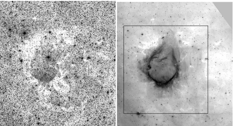
emission is a good tracer of the hot PDR that surrounds the H region. Figure 2 shows that PAH emission completely sur-rounds the ionized gas. Filaments extend far from the ionization front, suggesting the idea of a ‘leaky’ H region, probably due to small-scale inhomogeneities in the ionization front and in the surrounding medium. This point is important, as it could ex-plain how triggered star formation may occur far from the ion-ization front (see Sect. 5.2). Figure 3 (left) is a mosaic KSimage
of RCW 120 from the 2MASS survey. This clearly shows the presence of an absorbing region surrounding RCW 120, with some filamentary structures that extend far from the ionized re-gion. The clear limits of the absorbing zone and its large width (especially to the north) suggest that we are seeing the remain-ing part of the parental molecular cloud. The right part of Fig. 3 shows, on the same scale, an image of the RCW 120 region, taken from the Spitzer-GLIMPSE survey in the band centred at 8 µm. The absorption zones, clearly visible at 2 µm, are still observed at 8 µm (especially to the north), indicating the pres-ence of high-density material in those regions. Lacking velocity
information, we cannot prove the direct association of the ab-sorbing zones with the ionized region. The high contrast seen at 2 µm (Fig. 3 left), between the absorbing zones that closely surround RCW 120 and the surrounding medium observed at a larger distance, indicates that the association may be real. The black box shown in Fig. 3 on the 8 µm GLIMPSE image shows the zone that we have selected to search for YSOs using colour criteria in the near and mid IR. This part is described in Sect. 4.2.
3. Observations
Of the two sets of observations, the SEST-SIMBA contains continuum maps at 1.2-mm (250 GHz) of a 20′×20′field
cen-tred on RCW 120 were obtained using the 37-channel SIMBA bolometer array (SEST Imaging Bolometer Array) on May 7-8, 2003. The beam size is 24′′. The positional uncertainty of
the SIMBA observations is less than 3′′. Six individual maps
covering the whole region were obtained with the fast scan-ning speed (80′′per second). The total integration time was 10
Fig. 3. Dust associated with RCW 120. Left: KS (2.17 µm) mosaic image of the RCW 120 region from the 2MASS survey.
Zones of high absorption surround the ionized region. Absorption filaments extend far away from the ionization front, revealing a non-homogenous medium. Right: PAH emission at 8 µm from Spitzer-GLIMPSE. Absorption features are still seen at this wavelength, indicating the presence of dense material. The black box represents the region that has been searched for young stellar objects
hours. The final map was constructed as described in Zavagno et al. (2006). The residual noise in the final map is about 20 mJy/beam (1σ). We then used the emission above 5σ (100 mJy/beam level) to delineate the 1.2-mm condensations.
The Hα Fabry-Perot observations of RCW 120 were ob-tained with CIGALE on a 36-cm telescope (La Silla, ESO). CIGALE uses a Fabry-Perot interferometer scanning the Hα profile to give the kinematics over the field. The field of view is 39′square with a pixel size of 9′′. The Fabry-Perot
interferom-eter has an interference order of 2604 at Hα, i.e. a free spectral range of 115 km s−1. The finesse is 10 (FWHM 11.5 km s−1)
and the sampling step is 5 km s−1. The velocity and FWHM
uncertainties are both ∼1 km s−1. A complete description of
the instrument, including data acquisition and reduction tech-niques, can be found in Le Coarer et al. (1992).
The Hα profiles need to be decomposed into two compo-nents: the night-sky lines (geocoronal Hα and OH) and the neb-ular lines. The night-sky lines are modelled by the instrumen-tal profile, while the nebular lines are modelled by Gaussians convolved with that profile. In order to increase the signal-to-noise ratio we extracted and analysed profiles from large areas (45′′×45′′). The profile analysis shows that the LSR radial
ve-locity of the ionized gas of RCW 120 ranges from −8 km s−1
to −15 km s−1.
4. Results
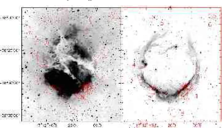
Figure 4 (left) shows the 1.2-mm continuum emission contours superimposed on a SuperCOSMOS Hα image of RCW 120. Eight condensations are observed at a 5σ level. Five of these (nos 1, 2, 3, 4, and 7) are immediately adjacent to the ionized region. This location suggests that these condensations may re-sult from the fragmentation of a layer of collected material ac-cumulated between the ionization front and the shock front, as predicted by the collect and collapse model. The two most massive condensations (nos 1 and 2) are observed to the south. Condensations 5, 6, and 8 are observed farther away from the ionization front but coincide with regions of high extinction in Fig. 3. Note that only low extinction is detected in the optical and 8 µm images in the direction of the most massive conden-sations (1 and 2), indicating that most of the absorbing material must be located behind the emitting region.
Figure 4 (right) presents the 1.2-mm continuum emission contours superimposed on the 5.8 µm GLIMPSE image of RCW 120. The lowest contour delineates the condensations’ surfaces as defined, for the mass estimates, at the 5σ level (100 mJy/beam, Sect. 3).
4.1. Mass estimates
The millimetre continuum emission from the condensations identified in Fig. 4 (right) is mainly due to optically thin ther-mal dust emission. We used the formula given by Hildebrand
A. Zavagno et al.: Triggered star formation on the borders of RCW 120 5
Fig. 4. Left: Millimetre continuum emission contours superimposed on a SuperCOSMOS Hα image of the region. Contours
range from 60 (3σ) to 960 mJy/beam in steps of 100 mJy/beam and from 1000 to 3000 mJy/beam in steps of 400 mJy/beam.
Right: Millimetre continuum emission contours superimposed on the GLIMPSE 5.8 µm image of the region. Contours range
from 100 mJy/beam (5σ) to 400 in steps of 100 mJy/beam and then from 500 to 3000 in steps of 250 mJy/beam. Condensations at 1.2 mm are identified in Table 1
Table 1. Mass estimates for the millimetre fragments
Number Peak position F1.2mm1 Mass range2
α2000 δ2000 (mJy) (M⊙) 1 17h12m08.s94 −38◦ 30′ 43.′′ 20 16100 278 – 465 2 17h12m34.s16 −38◦30′51.′′95 4100 71 – 118 3 17h12m44.s78 −38◦ 29′ 28.′′ 30 540 9 – 15 4 17h12m41.s50 −38◦27′07.′′43 797 13 – 23 5 17h12m32.s06 −38◦ 19′ 48.′′ 30 323 5 – 9 6 17h11m47.s90 −38◦19′48.′′28 1003 18 – 30 7 17h11m58.s72 −38◦ 28′ 27.′′ 18 422 7 – 12 8 17h12m19.s82 −38◦ 34′ 04.′′ 14 984 17 – 28
11.2-mm flux integrated above the 5σ level 2The lower mass is calculated for T
dust=30 K, the higher mass for Tdust=20 K
(1983) and proceeded as explained in Zavagno et al. (2006). Table 1 lists the measured and derived properties obtained for the millimetre fragments identified in Fig. 4. Column 1 gives the fragment numbers, columns 2 and 3 give the emission peak coordinates, column 4 gives the 1.2-mm integrated flux, and column 5 the range of derived masses for the corresponding fragment depending on the adopted temperature (20 or 30 K). The lower mass values correspond to the higher dust tempera-ture. Because of possible molecular line contamination (over-estimation of the continuum flux) and the possible presence of
an internal source of heating (a higher dust temperature than expected), the fragments’ mass estimate is an upper limit (see also Beuther et al. 2002). If an outflow is present, the molec-ular line contamination to the measured 1.2-mm flux may be as much as 30% (Gueth et al. 2003) but is probably about 10% if no outflow is present (Guilloteau, private communication). The two most massive fragments, nos 1 and 2, are located to the south, probably a consequence of the higher density in this area. The other fragments, located on the borders of the ionized region or even farther away, are less massive. Fragment 1 shows
some structure, in particular a highly peaked emission. The 1.2-mm emission peak of 3.08 Jy/beam indicates an H2 column
density greater than 3.5 ×1023cm−2for a temperature of 20 K, corresponding to a visual extinction AV≥200 mag. This
frag-ment is a potential site of high-mass star formation (see also Beuther et al. 2002). However, as discussed in Sect. 4.2, no 8 µm source is observed towards this emission peak. This could be due to the low sensitivity of the GLIMPSE survey. A source should be sought at longer wavelengths.
4.2. Search for young stellar objects using 2MASS and GLIMPSE data
Our purpose is to look for star formation towards RCW 120. For this we use the Spitzer-GLIMPSE survey to do a systematic search for YSOs using colour selection criteria. Indeed, YSOs are expected to have specific colours depending on mass and evolutionary status (see Allen et al. 2004). We have selected the absorbing zone, centred on RCW 120, seen in the near IR (Fig. 3), from α2000from 17h11m11.s05 to 17h13m17.s54 and
from δ2000from −38◦14′30.′′40 to −38◦40′40′′.
We extracted the 35178 objects in this zone from the GLIMPSE PSC (http://www.astro.wisc.edu/sirtf/). Then, to avoid sources near the detection limit, we selected the 2654 sources that had been measured in the four IRAC bands and were brighter than 11 mag in the 8 µm band. From these we se-lected those objects with colours corresponding to Class II and Class I, i.e. [3.6] − [4.5] ≥ 0.4 and [5.8] − [8.0] ≥ 0.4 (Allen et al. 2004). The final selection is listed in Table 2 to which we have added the exciting star of RCW 120 and a few giants.
Table 2, available at the CDS (http://cdsweb.u-strasbg.fr/A+A.htx), gives the position and photometry from 1.25 µm to 8 µm of the detected YSOs, sorted by location (towards the millimetre condensations, towards and outside from the H region). Column 1 gives their identification numbers. Columns 2 and 3 give their coordinates accord-ing to the GLIMPSE PSC. Columns 4 to 6 give their J,
H, and KS magnitudes from the 2MASS PSC
(http://tdc-www.harvard.edu/software/catalogs/tmpsc.html). Columns 7 to 10 give their [3.6], [4.5], [5.8], and [8.0] magnitudes from the GLIMPSE PSC. When not available from the PSC, we measured the magnitudes (aperture photometry) using the Basic Calibrated Data frames; these are indicated with asterisks in Table 2. Column 11 gives general comments about the nature of each source (Class I, Class II, giant).
4.3. Properties of the observed sources
Several tools can be used to determine the nature of the sources, using their IR magnitudes from the 2MASS, Spitzer-GLIMPSE, and MSX surveys.
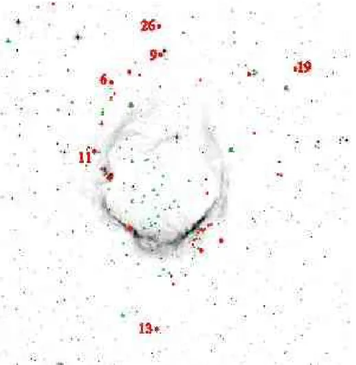
Figure 5 shows the spatial distribution of the Class I and Class II YSOs identified in the direction of RCW 120 and shows that these YSOs are located in three main zones: i) near the cold dust condensations identified in Fig. 4; ii) in the direc-tion of the ionized region; and iii) far from the ionizadirec-tion front and, in some cases, not associated with a detected millimetre
condensation. The lack of velocity information makes it im-possible to firmly associate the detected YSOs with RCW 120. However, the statistical analysis presented in Sect. 5.2 sug-gests that most of these objects are associated with this region. The GLIMPSE colour-colour diagram is shown in Fig. 6. The sources discussed in the text are identified by the labels given in Table 2. A large number of objects are Class I sources. We do not consider those sources located in the lower part of the Class II box, since main sequence and giant stars (located in the elliptical region centred on 0,0 in this [3.6] − [4.5] versus [5.8] − [8.0] diagram) may be falsely displaced into this zone if they are faint and superimposed on background emission (the colours of the extended emission are [3.6] − [4.5] = 0.1 and [5.8] − [8.0] = 1.9). Giant stars can be bright IR sources. We used the 2MASS J − H versus H − K diagram, not presented here, to identify such stars.
Note that the colour-colour diagrams do not give informa-tion about the sources’ brightnesses and that addiinforma-tional infor-mation is needed to better discuss the nature of the sources. We do not discuss the spectral energy distribution (SED) in this paper, because the 2MASS data for the embedded sources are often missing (or are given as lower limits) and also because the wavelength coverage of GLIMPSE is too limited to accurately fit the SEDs, especially since GLIMPSE sees only part of the deep silicate absorption that is often present in YSOs. Longer wavelength data are needed to use the SED as a reliable tool for evolutionary and brightness classifications.
Below we give information about some specific properties of the sources, due either to their locations and/or evolution-ary stages. Sources observed towards millimetre condensations may be affected by local extinction. Apparently, Class I sources may in fact be reddened Class II. This is particularly critical for deeply embedded sources classified as Class I with no 2MASS counterparts.
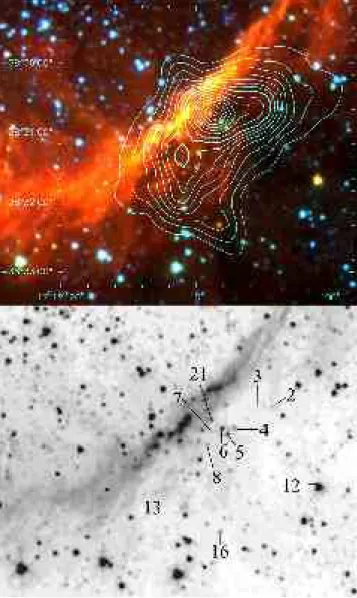
Condensation 1
Figure 7 is a composite colour image of condensation 1. Source 12C1, the brightest object at 8 µm near condensation 1, is lo-cated in the transition region between Class I and Class II sources (Fig. 6). This source is not directly associated with 1.2-mm emission but is observed towards a filamentary struc-ture observed in absorption at 8 µm (see Fig. 3); it is far (about 1.2 pc) from the ionization front but is observed surrounded by diffuse 8 µm emission, indicating that far UV photons leaking from the ionized region have reached this zone. This radiation may have influenced the formation of this young source. We discuss this point in Sect. 5.2.
Source 16C1, a Class I object, is the brightest source ob-served towards condensation 1, and it has no 2MASS counter-part. This source coincides with an extension of the 1.2-mm continuum emission and is observed at the head of a finger-shaped absorbing region observed at 8 µm. Faint 8 µm emission surrounds this region, indicating that UV photons reach this zone. The location of this source at the vertex of an absorbing structure indicates that globule squeezing may have occurred here, triggering star formation.
Source 13C1 is also a Class I object having no 2MASS counterpart. It is observed in the direction of a 1.2-mm emis-sion extenemis-sion.
A. Zavagno et al.: Triggered star formation on the borders of RCW 120 7
Fig. 5. Spatial distribution of the YSOs detected towards RCW 120. The red circles are Class I sources, the green triangles Class
II sources. In both cases, the largest symbols are for the brightest sources, with [8.0] ≤6 mag. Bright Class I sources observed far from the ionization front are identified (see Sect. 5.2). The field size is 25′ (E-W) × 25.′5 (N-S)
The sources 4C1, 5C1, 6C1, 7C1, 8C1, and 21C1 are ob-served towards the main 1.2-mm emission peak. Most of these are low-luminosity Class I objects. This strong emission peak does not coincide with an absorbing zone at 8 µm, so the con-densation must be located behind the 8 µm emitting region. The nature of source 21C1, observed exactly coincident with the 1.2-mm peak, is unclear, as this source has no measured mag-nitudes in the [3.6], [5.8], and [8.0] bands.
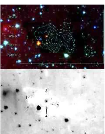
Condensation 4
Figure 8 shows a detailed view of condensation 4. As seen in Fig. 8, two bright extended sources called objects 1 and 2 and not given in the GLIMPSE PSC (probably due to their extended nature), dominate the 8 µm emission. At their centres lie near-IR stellar objects. Objects 1 and 2 are also seen in the MSX images and are classified from their MSX colours as Herbig Ae/Be objects (for object 1 see source 19 in Deharveng et al. 2005). We have verified from its MSX colours that object 2 (not included in Deharveng et al. 2005) is a Herbig Ae/Be object as well. The extended nebulae are probably local PDRs created by the radiation of the central sources. These are not massive enough to form H regions but they can, with lower energy photons, heat the surrounding dust, thus creating local PDRs.
Class I sources including nos 2, 3, and 4C4, are observed in the immediate surroundings, in addition to these two Herbig Ae/Be stars. No source is detected towards the peak of the 1.2-mm condensation. Note that the shape of the ionization front is distorted in the direction of condensation 4. We discuss this point in Sect. 5.2.
Condensation 5
Condensation 5 is observed far from the ionization front and coincides with a region of high extinction observed at both 2 µm and 8 µm (Fig. 3). An interesting point is the presence of numerous radial structures seen in absorption at 8 µm, per-pendicular to the IF (Fig. 3). This suggests that radiation passes through this rather dense medium, with enough energy to shape it, and may have favoured subsequent star formation within this possible pre-existing condensation.
Two Class I sources, 1C5 and 2C5, are observed towards condensation 5. The bright source 1C5 is observed towards the condensation’s centres.
Condensation 6
Figure 9 shows condensation 6 in detail. This object, like con-densations 5 and 8, is observed far from the ionization front (about 1.5 pc away) and coincides with an absorption region seen in the 2 µm and 8 µm images (Fig. 3). Five sources are
Fig. 6. GLIMPSE colour-colour diagram, [3.6] − [4.5] versus [5.8] − [8.0], for the sources observed towards RCW 120. Class I
and Class II zones are indicated according to criteria given by Allen et al. (2004). The black arrow is the reddening vector for a visual extinction of 40 mag. The ellipse centred on 0,0 encloses the region of main sequence and giant stars. The black star represents the exciting star of RCW 120
observed towards condensation 6, source 5C6 being the bright-est. Source 3C6 is a very faint red object observed towards the peak of the 1.2-mm emission (Fig. 9). Objects 2C6 and 4C6, also classified as Class I, are located farther from the centre of the 1.2-mm emission peak.
Sources observed towards the ionized region
As seen in Table 2 and in Fig. 5, all of the sources observed towards the ionized region are Class II objects, apart from one Class I source, 13H . The ionizing star of RCW 120 is iden-tified in Fig. 1. Its GLIMPSE colours correspond to those of main sequence stars (Fig. 6).
A Class I source (5H ) and a Class II source (1H ) are ob-served towards the ionized region, lying on the vertices of trian-gular structures. Both (the sources and the structures) are seen in emission at 8 µm (see Fig. 12) and are discussed in Sect. 5.1.
4.4. H
α
velocity fieldFigure 10 presents the velocity field of the ionized gas observed towards RCW 120 and the width of the Hα emission line over the field. The uncertainty of the Hα line width is 1 km s−1. The velocity field displays a gradient, from about −9 km s−1to the
south of the H region, up to −16 km s−1 to the north of the
region. In Fig. 2 RCW 120 looks like a bottle full of ionized gas, its ‘neck’ turned to the north where a clear opening in the 8 µm indicates a break in the ionization front and the surround-ing dust layer. The Hα velocity field shows that the ionized gas flows towards the observer. This result is consistent with the most massive condensation being located to the south where dense material has accumulated. The northern part is proba-bly less dense, allowing the ionized gas to break the
surround-ing shell and flow away. We are probably observsurround-ing the be-ginning of a ‘champagne’ phase (Tenorio-Tagle 1979), and the observed shape of the region is also consistent with this result. Figure 10 shows that on the borders of the ionized region the Hα line width is narrow – around 18 km s−1– when
com-pared to the central parts where the width is ≃24 km s−1. This is
expected for an expanding H region: whereas the expansion velocity has no radial component on the borders of this region (thus the line is narrow), the expansion velocity is purely radial in the direction of the centre and we see both the approaching and receding sides (thus broadening the line). We expected this to be confirmed by the H emission but it was not, as described below.
The H emission from the Southern Galactic Plane Survey (SGPS, McClure-Griffiths et al. 2005) is shown in Fig. 11, inte-grated between −10.72 km s−1and −15.66 km s−1. The angular
resolution of these observations is 40′′and the velocity
resolu-tion is 0.82 km s−1. The emission shows an annular structure.
The H region and condensations 1 and 2 lie in the direction of the central hole. The annular structure is larger near −11 km s−1(the systemic velocity) than near −15 km s−1, so the whole
structure appears to be in expansion. However, we only see the approaching side of the cloud, as no emission is observed around −5 km s−1, as would be expected from the receding side
of the cloud. We have no explanation for this fact.
5. Discussion
5.1. Star-forming processes at work in RCW 120
Several star-forming processes may be at work in the direction of RCW 120.
A. Zavagno et al.: Triggered star formation on the borders of RCW 120 9
Fig. 7. Top: colour composite image of condensation 1,
show-ing the K image (blue) from 2MASS, and the 3.6 µm (green) and 8 µm (red) image from the GLIMPSE survey. Bottom: The sources discussed in the text are identified on the 5.8 µm GLIMPSE image
•The collect and collapse process: we observe a collected layer of cold dust revealed by the 1.2-mm continuum emis-sion. We also observe fragments along this layer, suggesting that the collected material has already experienced fragmen-tation. Fragments 1, 2, and 3 are clearly separated along this layer and the ionized gas seems to be leaking between them (see Fig. 12 top). However, no massive star formation has been observed in the direction of these fragments, contrary to what is observed on the borders of Sh 104 and RCW 79. Note that the non-detection of an IR source at the peak of the 1.2-mm emission could be due to the high extinction we derive near this peak and to the low sensitivity of the GLIMPSE observa-tions. Deeper IR observations are needed to possibly establish the presence of an IR star forming in this condensation. The high-density peak observed in condensation 1 is probably the best place to search for massive YSOs.
Fig. 8. Top: Same as Fig. 7, but for condensation 4. The sources
discussed in the text are identified in the 8 µm GLIMPSE image (bottom)
•The radiation-driven implosions of pre-existing clumps: this is possibly the case for star formation associated with con-densation 4. The shape of the ionization front surrounding this condensation is clearly distorted, protruding inside the H re-gion. This situation is to be expected if the expanding ioniza-tion front encounters a moioniza-tionless dense clump. In this case star formation may result from the radiation-driven implosion of the clump (Lefloch & Lazareff 1994; Kessel-Deynet & Burkert 2003).
•Dynamical instabilities of the ionization front: the region located between condensations 1 and 2 is probably dynamically unstable. Figure 12 shows that the ionization front is locally distorted, with the ionized gas leaking between the condensa-tions. We also observe two triangular structures protruding into the ionized zone. Two YSOs, sources 1H and 5H , are ob-served at the vertices of these triangular structures (see Fig. 12 bottom). Such structures were possibly formed by the devel-opment of instabilities in the ionization front, as simulated by Garc´ıa-Segura & Franco (1996) and by Dale et al. (in prepara-tion). The latter simulation shows the formation of stars at the vertices of such structures.
Fig. 9. Same as Fig. 7 but for condensation 6. The sources
dis-cussed in the text are identified in the 5.8 µm GLIMPSE image (bottom)
5.2. Star formation observed far from the ionization front
Figure 5 presents the spatial distribution of the Class I and Class II YSOs identified towards RCW 120. It shows that many of these sources lie far from the ionization front – as far as 1.5 pc. Some examples are the bright Class I sources 6out, 9out, 11out, 13out, 19out, 26out, 1C5, 5C6, and 12C1. The radial structures clearly visible in absorption on the northeastern and southwestern sides of the region (see Fig. 3 right) are striking evidence of interaction between the radiation leaking from the IF and the surrounding medium.
In the absence of velocity information, it is impossible to be sure that the observed YSOs are all associated with RCW 120. Only a statistical approach can give us some in-sight into this point. We have considered two zones located at the same Galactic latitude as RCW 120 (b = 0.◦499) and on either side of it (at Galactic longitudes l = 347.◦16 and l = 349.◦16). Each of these zones has the same area as the
re-gion we searched for YSOs around RCW 120 (Sect. 4.2). The same selection criteria was applied to search for Class I and Class II sources in these zones as in RCW 120 (i.e. [3.6] − [4.5] and [5.8] − [8.0] ≥0.4 mag). The result is as follows: 15 and 25 YSOs, respectively, are detected in these zones compared to 107 YSOs in the RCW 120 zone. This suggests that most of the YSOs detected towards RCW 120 are probably associated with it.
Fig. 10. Top: Hα velocity field (grey scale plus black dashed
contours). Bottom: Hα line width (grey scale). The Hα emis-sion is superimposed as white contours
Which process can trigger star formation far from the ion-ization front? Figure 3 shows that low-brightness PAH emis-sion features also extend far from the ionization front. It seems that the hot photon-dominated region, where PAH emission originates, is more extended than would be expected if the ion-ization front were impermeable. Examination of a wide-field Hα image also clearly shows extended Hα emission surround-ing the RCW 120 region. This suggests a leaky H region bounded by a porous ionization front, allowing a fraction of the UV radiation to reach regions far away from the front.
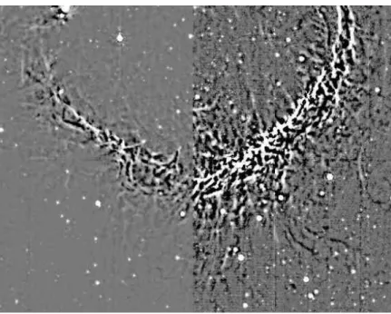
Figure 13 is an unsharp-masked image of the southern part of RCW 120 at 8 µm, obtained by subtracting a median-filtered version of the same image produced with a 12′′×12′′
win-dow from the original GLIMPSE image. The extended bright structures are thus removed, leaving the low-brightness, small-scale structures. The left part of Fig. 13 shows the highly ir-regular aspect of the IF. The right side, where the contrast has been enhanced, shows the outer part of the PDR, with many radial structures originating from the IF. This structure clearly indicates that the UV radiation can penetrate far inside the sur-rounding medium. Can the high pressure of the warm, partially
A. Zavagno et al.: Triggered star formation on the borders of RCW 120 11
Fig. 11. H emission (in white) from the SGPS integrated
be-tween −15.66 km s−1 and −10.72 km s−1. Hα emission is su-perimposed as green contours
ionized inter-clump medium trigger star formation far from the ionization front?
5.3. Comparison with models
The collect and collapse process of star formation, first pro-posed by Elmegreen & Lada (1977), has been formulated an-alytically by Whitworth et al. (1994; see also Dale, Bonnell and Whitworth 2007) and simulated by Hosokawa & Inutsuka (2005, 2006). All these models are spherically symmetric around the exciting star and assume that the H region ex-pands into a uniform medium of density n0. The assumption
of spherical symmetry is not too bad for RCW 120, but the ob-servations presented here indicate that the medium is far from homogeneous. However, no model takes this fact into account. A rough estimate of n0 can be obtained by assuming that
all the material now observed, either ionized in the H region or neutral in the massive fragments surrounding RCW 120, was previously located in a sphere of density n0 and of
ra-dius equal to that of the H region. We used only the south-ern half of RCW 120 for this estimate of n0. From the
radio-continuum flux density, we estimate the mass of ionized gas to be M(H ) = 54 M⊙(thus 27 M⊙ for half the H region).
The mass of neutral material in condensations 1, 2, 3, 4, and 7 is 633 M⊙(the maximum value, for T =20 K). The mass of
neutral material in the collected layer, but not detected in the direction of the centre of the H region because its emission is below the sensitivity limit of the 20 mJy/beam, is ≤ 185 M⊙
(thus ≤ 93 M⊙ for half the layer), hence an upper limit of
3000 atoms cm−3 for n
0. A lower limit of 1400 atoms cm−3
is obtained for T =30 K.
Fig. 12. Instabilities of the ionization front. Top: the ionized
gas traced by the Hα emission (in blue) leaks between con-densations 1 and 2, at the locations shown by the blue arrows.
Bottom: structure of the ionization front (GLIMPSE 5.8 µm
im-age). The black arrows point to two YSOs (1H and 5H ) ob-served at the vertices of triangular structures possibly created by dynamical instabilities in the ionization front
Fig. 13. Unsharp-masked image of the southern part of
RCW 120 at 8 µm (see text for details)
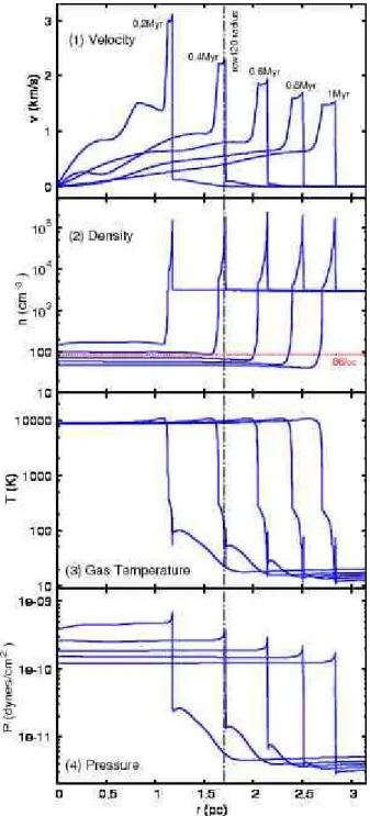
The dynamical expansion of RCW 120 and its PDR can be analysed using the model of Hosokawa & Inutsuka (2006). A one-dimensional, spherically symmetric numerical method is used. The UV and far-UV radiation transfer, as well as the thermal and chemical processes, are solved with a
time-dependent hydrodynamic code. We suppose a central star of 22 M⊙ (which, according to Diaz-Miller et al. 1998, emits
the same number of ionizing photons as the exciting star of RCW 120) and a uniform ambient density of 3000 atoms cm−3. Figure 14 shows the time evolution of several physical quantities. The radius of RCW 120, 1.67 pc, is reached at
t = 0.4 Myr. At this time the electron density of the ionized
gas agrees with the observed value of 86 cm−3. Figure 14 also shows the gas shell swept up by the shock front, with densities in the range 104–105cm−3; the highest density is found on the outside of the shell, close to the SF. The shell mass is about 1000 M⊙at this time, and most of the swept-up hydrogen gas
remains in the shell as hydrogen molecules. Figure 15 shows the evolution of the positions of various fronts. The swept-up shell very quickly becomes mainly molecular (H2); later on,
at about 0.3 Myr, the dissociation front of the CO molecule is engulfed by the expanding shell. Parts of the shell become unstable when t ≥ (Gρ)−1/2. Figure 15 shows that the
unsta-ble region appears at about 0.3 Myr, near the SF, and gradu-ally spreads over the shell. Thus we would expect to see, at the age of 0.4 Myr, a shell of mainly molecular collected material, with the outside parts of the shell (near the SF) fragmented. Of course, the model does not tell us if stars have already formed in these fragments. Note that these estimates are rough, due to the uncertainties concerning both the density and the unifor-mity of the medium into which RCW 120 evolves.
6. Conclusions
Although it apparently has a very simple morphology, the H region RCW 120 elicits several questions.
It appears as an almost perfect sphere full of ionized gas – a Str¨omgren sphere around the exciting star. The sphere is open in the direction of lower density, in the north, and the ionized gas is escaping from the sphere. We are most probably seeing the very beginning of a ‘champagne flow’. This is shown by the shape of the H region, the shape of its IF as shown by the PAH emission and by the velocity field.
Dense material, now mostly molecular, has been collected around the ionized gas during the expansion of the H region. The collected layer has begun to fragment. This is shown by the millimetre emission of the cold dust. Some fragments are massive, but no massive YSO is detected (up to 8 µm at the GLIMPSE sensitivity) in the direction of the fragments. If a massive Class 0 object is forming, it may be detectable but only at longer wavelengths at the emission peak of condensation 1.
Several Class I and Class II objects, of low and intermedi-ate mass, are observed in the direction of the PDR, near the IF. Their formation was probably triggered by the expansion of the H region, via various processes such as dynamical instabili-ties of the IF and the radiation-driven implosion of pre-existing molecular clumps.
Two other points are pending and need further observations for them to be understood:
– What is the origin of the shell of atomic hydrogen sur-rounding RCW 120? We suggest that it is part of the parental molecular cloud, photo-dissociated from the outside by FUV
Fig. 14. Snapshots of the gas dynamical evolution at t=0.2, 0.4,
0.6, 0.8, and 1.0 Myr
background radiation (Hosokawa 2007). But why do we ob-serve only half a shell of H material (the half-shell approach-ing us)?
– Several YSOs are observed far from the ionization front. Are they associated with RCW 120? We have no proof that any specific YSO is associated with RCW 120, but a statistical test suggests that most of them are associated. If this is the case, what physical process can trigger star formation far from the ionization front?
This point is very important and is probably linked to the structure of the PDR. We are most probably dealing with a leaky H region, in the sense that the ionization front is
per-A. Zavagno et al.: Triggered star formation on the borders of RCW 120 13
Fig. 15. Top: Evolution of the positions of the various fronts
(ionization front [IF], shock front [SF] and dissociation front [DF] of the H2and CO molecules). Bottom: Time evolution of
the column density of the H2and CO components. The shaded
region corresponds to t ≥ (Gρ)−1/2within the shell and hence
indicates that gravitational fragmentation is expected. The con-tours show where the fractions of molecular gas XH2 (dashed
contours) and XCO(dot-dashed contours) = 0.2, 0.5, and 0.8
meable to the UV photons (hν >13.6 eV). This is shown by the presence of a low-brightness Hα zone surrounding RCW 120, which has the same shape and almost the same extent as that of the low-brightness PAH PDR. The low-density PDR, beyond the collected layer, appears to be very irregular. If hydrogen-ionizing UV photons escape from the H region, they ionize the low-density inter-clump medium, destroying the PAH there. The photons may carve radial tunnels. Lower energy photons heat PAHs at the surface of the high-density neutral clumps. The pressure of this partially-ionized, high-temperature, inter-clump medium may trigger star formation in the low-mass clumps.
If real, such structures and such signatures of star forma-tion should be found around other H regions. Long-distance triggering by radiation through a permeable medium should be investigated in more detail by models and observations, as the results may change our view of triggered versus spontaneous star formation.
Acknowledgements. This research has made use of the Simbad as-tronomical database operated at the CDS, Strasbourg, France, and of the interactive sky atlas Aladin (Bonnarel et al. 2000). Our long-term collaborators on this project, B. Lefloch, J. Brand and F. Massi, are warmly thanked for stimulating discussions. We thank R. Cautain for his help in creating the KSmosaic image of RCW 120. We thank the
anonymous referee for important comments that helped to clarify the text. This publication used data products from the Midcourse Space
EXperiment, from the Two Micron All Sky Survey, and from the InfraRed Astronomical Satellite; for these we used the NASA/IPAC Infrared Science Archive, which is operated by the Jet Propulsion Laboratory, California Institute of Technology, under contract with the National Aeronautics and Space Administration. We also used the SuperCOSMOS Hα survey. This work is based in part on GLIMPSE data obtained with the Spitzer Space Telescope, which is operated by the Jet Propulsion Laboratory, California Institute of Technology, un-der NASA contract 1407.
References
Allen, L.E., Calvet, N., D’Alessio, P., Merin, B., Hartmann, L., Megeath, S.T., Gutermuth, R.A., Muzerolle, J. Pipher, J.L., Myers, P.C., Fazio, G.G., 2004, ApJS, 154, 363
Altenhoff, W.J., Downes, D., Goad, L., Maxwell, A., Rinehart, R., 1970, A&AS, 1, 319
Avedisova, V.S., Kondratenko, G.I., 1984, Naucnye Informacii, 56, 59 Benjamin, R.A., Churchwell, E., Babler, B.L., Bania, T.M., Clemens, D.P., Cohen, M., Dickey, J.M., Indebetouw, R., Jackson, J.M., Kobulnicky, H.A. et al. 2003, PASP, 115, 953
Beuther, H., Schilke, P., Menten, K.M., Motte, F., Sridharan, T.K., Wyrowski, F. 2002, ApJ, 566, 945
Blitz, L., Fich, M., Stark, A.A., 1982, ApJSS, 49, 183
Bonnarel, F., Fernique, P., Bienayme, O., Egret, D., Genova, F., Louys, M., Ochsenbein, F., Wenger, M., Bartlett, J.G. 2000, A&ASS, 143, 33
Brand, J., Blitz, L., 1993, A&A, 275, 67
Dale, J.E., Bonnell, I.A., Whitworth, A.P. 2007, MNRAS, 375, 1291 Deharveng, L., Lefloch, B., Zavagno, A., Caplan, J., Whitworth, A.P.,
Nadeau, D., Martin, S., 2003, A&A, 408, L25
Deharveng, L., Zavagno, A., Caplan, J. 2005, A&A, 433, 565 Diaz-Miller, R.I., Franco, J. 1998, ApJ, 501, 192
Elmegreen, B. G., Lada, C.J. 1977, ApJ, 214, 725
Elmegreen, B. G. 1998, in ASP Conf. Ser., 148, 150 ed. C. E. Woodward, J. M. Shull & H. A. Tronson
Egan, M. P., Price, S. D., Moshir, M. M., et al. 1999, The Midcourse Space Experiment Point Source Catalog Version 1.2, Explanatory Guide, AFRL-VS-TR-1999-1522, Air Force Research Laboratory Garc´ıa-Segura, G., Franco, J. 1996, ApJ, 469, 171
Georgelin, Y.P, Georgelin, Y.M. 1970, A&ASS, 3, 1 Gorti, U., Hollenbach, D. 2002, ApJ, 573, 215
Griffith, M.R., Wright, A.E., Burke, B.F., Ekers, R.D., 1994, ApJS, 90, 179
Gueth, F., Bachiller, R., Tafalla, M. 2003, A&A, 401, L5 Hildebrand, R.H. 1983 Q.Jl. R. astr. Soc., 24, 267 Hosokawa, T., Inutsuka, S. 2005, ApJ, 623, 917 Hosokawa, T., Inutsuka, S. 2006, ApJ, 646, 240 Hosokawa, T. 2007, A&A, 463, 187
Kessel-Deynet, O., Burkert, A. 2003, MNRAS, 338, 545
Langston, G., Minter, A., D’Addario, L., Eberhart, K., Koshi, K., Zuber, J., 2000, AJ, 119, 280
Le Coarer, E., Amram, P., Boulesteix, J., Georgelin, Y. M., Georgelin, Y. P., Marcelin, M., Joulie, P., Urios, J. 1992, A&A, 257, 389 Lefloch, B., Lazareff, B., 1994 A&A, 289, 559
Manchester, B.A., 1969, AuJPA, 12, 3
Martins, F., Schaerer, D., Hillier, D.J., 2005, A&A, 436, 1049 Martins, F., Plez, B., 2006, A&A, 437, 637
McClure-Griffiths, N.M., Dickey, J.M., Gaensler, B.M., Green, A.J., Haverkorn, M., Strasser, S. 2005, ApJS, 158, 178
Parker, Q.A., Phillipps, S., Pierce, M. J., Hartley, M., Hambly, N. C., Read, M. A., MacGillivray, H. T., Tritton, S. B., Cass, C. P., Cannon, R. D., et al. 2005, MNRAS, 362, 689
Peeters, E., Tielens, A.G.G.M., Boogert, A.C.A., Hayward, T.L., Allamandola, L.J. 2005, ApJ, 620, 774
Reifenstein III, E.C., Wilson, T.L., Burke, B.F., Mezger, P.G., Altenhoff, W.J., 1970, A&A, 4, 357
Rodgers, A. W., Campbell, C. T., Whiteoak, J. B. 1960, MNRAS, 121, 103
Russeil, D. 2003, A&A, 397, 133 Sharpless, S., 1959, ApJS, 4, 257 Sellgren K. 1984, ApJ, 277, 623
Simpson, J.P., Rubin, R.H. 1990, ApJ, 354, 165
Skrutskie, M.F., Cutri, R.M., Stiening, R., Weinberg, M. D., Schneider, S., Carpenter, J. M., Beichman, C., Capps, R., Chester, T., Elias, J. et al. 2006, AJ, 131, 1163
Tan, J.C., McKee, C.F. 2001, in Starburst Galaxies: Near and Far, eds. L. Tacconi and D. Lutz, Springer Verlag, 188 (astro-ph/0012005) Tenorio-Tagle, G. 1979, A&A, 71, 59
Verstraete, L., Puget, J.L., Falgarone, E., Drapatz, S., Wright, C.M., Timmermann, R. 1996, A&A, 315, L337
Whitworth, A.P., Bhattal, A.S., Chapman, S.J., Disney, M. J., Turner, J.A. 1994, MNRAS, 268, 291
Zavagno, A., Deharveng, L., Comeron, F., Brand, J., Massi, F. et al. 2006, A&A, 446, 171


![Fig. 6. GLIMPSE colour-colour diagram, [3.6] − [4.5] versus [5.8] − [8.0], for the sources observed towards RCW 120](https://thumb-eu.123doks.com/thumbv2/123doknet/14609549.545259/9.892.75.567.123.505/fig-glimpse-colour-colour-diagram-versus-sources-observed.webp)