Design and Prototype of a Lamp Build Kit for STEM Education
by OFT
Lauren L. Wright
JUL
LIB
Submitted to the Department of Mechanical Engineering in
Partial Fulfillment of the Requirements for the Degree of Bachelor of Science at the Massachusetts Institute of Technology
June 2016
C 2016 Lauren L. Wright all rights reserved
USETTS INSTITUTE _STT ILNSTITUTE ECHNOLOGY
08 2016
RARIES
RCHNVES
The author hereby grants to MIT permission to reproduce and to distribute publicly paper and electronic copies of this thesis document in whole or in part in any medium now known or
hereafter created.
Signature of Author
Signature redacted
Department of Mechpical Engineering May 6, 2016
Signature redacted
Certified byAccepted by
C." Maria Yang
Associate Professor of Mechanical Engineering Thesis Supervisor
Signature redacted_
Anette Hosoi Associate Department Head for Education; Professor of Mechanical Engineering Chairman, Undergraduate Thesis Committee
Design and Prototype of a Lamp Build Kit for STEM Education
by
Lauren L. Wright
Submitted to the Department of Mechanical Engineering on May 6, 2016 in Partial Fulfillment of the Requirements for the Degree of Bachelor of Science at
the Massachusetts Institute of Technology
Abstract
This thesis describes a case study of an early phase product design process. Company J is a startup toy company creating toys that encourage STEM education and participation. One product in their anticipated lineup is a lamp construction kit. Through the process of assembling users learn about basic engineering and electronics concepts. This project concerns redesigning an early-stage prototype to further the product development and move it towards mass-manufacturability. The design process began with different levels of ideation and concept selection. Then, models were made both virtually and physically to attain user feedback. Once the final design was selected, more advanced prototyping methods were used to create a next-generation prototype.
1. Introduction
The focus of this thesis is a case study of the early stage design process for a new consumer product. Company J is a startup toy company that intends to produce toys that encourage STEM education and participation in children, specifically targeted at young girls. Company J's products differ from other STEM-oriented toy companies in that there is an intended end product; many engineering-related toys are build kits that have no permanent form.
One item in Company J's anticipated product lineup is a lamp construction kit. This kit requires the user to assemble both the electronic components and outer pieces of the lamp. The light comes not from a lightbulb but from a ring of LEDs within the transparent body of the lamp. Through the process of assembling this lamp, users learn about basic engineering concepts related to electronics and components. The final product also allows for creative expression with options
for modification and customizability.
This project concerns redesigning an early-stage prototype of this lamp in order to receive further user feedback, solidifying the aesthetic direction of the project, and creating more highly refined prototypes, in addition to designing with considerations for mass-manufacturability for future iterations of the product.
2. Design Process
The design of the lamp was based off of an original concept and initial round of prototyping and user testing. Early feedback helped to inform the general aesthetic and visual properties of the lamp. The design process began with a phase of rapid ideation then moved into a period of informed selection. After a general form had been chosen, a period of design refinement served to move the concept into a next-level prototype. Design of the physical structure of the lamp happened in tandem with design of the internal electronics.
2.1 Design Considerations and Constraints
The starting point for this project was an early-model prototype of a lamp as seen in figure
1. This prototype was made with low budget materials to serve as both a proof-of-concept and to
provide a physical, working model for initial user feedback studies. This prototype was made primarily with rapid-manufacturing methods. The hexagonal base was constructed out of pieces of finger-slotted laser-cut acrylic. The shade was another piece of laser cut acrylic strung with plastic cord and s-hooks to hold together laser-cut sequins. The body of the lamp consisted of two plastic cups with a wavy outer surface taped together opening to opening. These cups were chosen due to their refractive properties. The electronics consisted of RGB LEDS, a breadboard circuit, potentiometers, and a battery pack all controlled with an Arduino.
The lamp consists of three basic sections; the base, the body, and the shade. Constraints on the designs for each part were due to matters of purpose, function, and usability. The base needed to be capable of housing the necessary electronics, consisting of a PCB with a microcontroller. The base also needed to incorporate a built-in battery compartment. The body needed to be optically clear and produce similar visual effects to the cups in the prototype. The body must also be capable of containing a revised LED ring. The shade needed to be removable and customizable. The parts needed to fit together with limited use of fasteners and in a manner that could feasibly be done by one person unaided. All parts also needed to be small and simple enough for children to assemble, with additional considerations towards durability.
When approaching a redesign of this prototype, the aesthetics needed to be taken into consideration with equal importance as the purpose and function of each part. The eventual product needed'to visually appealing enough to entice both buyers and users, i.e. parents and their children respectively. The designs also needed to be unique enough to differentiate the product from other
similar items on the market while still clearly communicating the lamp's purpose.
The lamp's construction also needed to provide for a positive assembly experience. Because the lamp is a build kit and not a standalone product, the experience of putting it together is as integral to the product as its final appearance. Choices made on fastener types, shape, weight, and height as well as internal mounting points for electronics were in large part informed by the effect these choices would have on the assembly experience.
The eventual goal of this project is to create a design that could be reasonably mass-produced. Injection molding the parts out of plastic was the logical manufacturing decision, but this method brings with it some design constraints. Parts needed to be in a form that could be split such that there was minimal overhang. Draft angles needed to be considered, as did areas of possible sinkage. Wall thicknesses needed to be optimized for both strength and minimal material usage.
2.2 Ideation
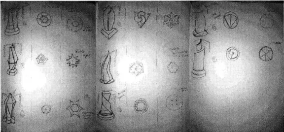
Given the design constraints and considerations, the prototype redesign process began with a period of ideation into two branches of a general design aesthetic. The lamp could either look more organic or synthetic in nature. Possible design inspirations ranged from cacti and sea creatures to skyscrapers and sculptural vases. Of these aesthetic categories to be explored, six were chosen to proceed with image research. This image research consisted of searching for images that could further inform and inspire the design of the lamp, primarily the shape of the lamp body. Image research was conducted via Google image search in an iterative process; search terms would progress from "cacti" to "rows of succulents" to "Echeveria" based on previous results. Images that were selected as useful were ones that could be reasonably translated into a physical design. After image research had been compiled, initial concept sketches, two to six per category, were created for each collection of images. The concept sketches included varying levels of symmetry and abstraction and were not tied to the form factor of the earlier prototypes. The purpose of this stage of the design process was to generate a wide range of possibilities for the form of the lamp that were not constricted by initial prototyping methods.
"4 4'< 1 '7 '7 7 74~, ./. 471. ~9 r
,:~
~ fl 47 77 ~ ~j44!il~44 4 ~ $147 ':444 ~Jt' it @wt '1Kv 7 4 ~'1l I . 44 ~> "4. . . 4 #', . . 447t 77 (:!: '47 4K N ~t441 4447kb '5 :4 /4< /sU//! 74< 4 '7<;; 47 7 774'? 7'.' 7777% 1St [7< :.7777y'.<:'1/ 747 7 7:7777 777t' .<777?:/;7' : 77;;:Concept sketches were discussed within the team to determine which designs to pursue further. In this stage of selection, main considerations were how the wavy pattern that worked well on the cup prototype could be applied to these new concepts. Other considerations were stability. how safe the design looked, whether or not the design was too "themed," and the ability of the design to appeal to children of any gender.
2.3 Design Selection
Once a concept was selected - for this project, the final decision was to use a gem-inspired
look - more designs were sketched within that concept. Here, proportions and abstraction were
played with more. In addition, more thought was given to bases and shades and how they would interface with the lamp body. Eleven designs that took inspiration from gemstones were sketched; from these, four body designs, two base designs, and one general shade style were chosen to move into more advanced modeling for user testing.
These 'second-round" sketch designs, as seen in figure 2, were narrowed down by considering a number of factors. At this point in the process, most of the designs had been deemed possible to manufacture, but some designs that included more symmetry lent themselves to this task better. Decisions were also made with the fact that the next round of prototypes would likely need to be 3D printed. Certain designs were more feasible to print and thus made the cut where others did not. Certain designs made more practical sense when consideringL mounting electronics; the L ED ring could be easily concealed in only some of the body designs.
IFigure 2: Eaniples toncept expioration sketches wil? a IoLUs 0n mOje gem-like designs.
Once this process of narrowing down had occurred, the next step was to obtain feedback from a target audience and to create some other models. This required the creation of rendered images of the four different body designs and the two different base designs. Images of each lamp with and without the shade were shown to several sets of both moms and children. In addition to the rendered images, paper models were made of the two base designs to obtain a physical understanding of the size and stability of each base. The combination of user feedback and insights gained from the paper models helped to inform the decision towards a final design direction.
~7A~~A
Figure 3: Rendered niages comparing some o the lamp bodies, showing them with and without shades. These images vere
Shown to Potential users in order to receive lhir oteedbai. From heir teddbak. a variation om the designs was chosen jar farther Pursu it
2.4 Design Refinement and Details
Once the aesthetic direction of the lamp had been chosen, detailed modeling of the design began, with a specific attention towards features necessary to the product's function. Though the details for the outside of parts had been modeled, much of the internals had not yet been decided on. Most of the fine details were determined through iterations of models in Solidworks.
For the lamp body, the biggest initial decision was how many pieces it would be split into, and in what orientation. One option was to divide it horizontally into three pieces. This orientation would be simple to injection mold due to its lack of overhang [show image comparison], but would require the use of fasteners to secure the parts together and to secure the LED ring. Splitting it in half along its axis allowed for convenient housing of the LED ring and fewer molds, but left the two halves potentially causing molding issues with overhang due to the wavy surface. In addition
there were concerns about the two halves flexing independently of one another. The benefits of using a two part model outweighed the possibility of molding issues which could be minimized. The amplitude of the wavy pattern was reduced until overhang became essentially nonexistent.
The potential for the two halves to flex independently of one another became the next big design hurdle for the lamp body. To prevent the halves from slipping across one another at the parting line, a raised lip on one side of the half and an indented groove on the other side created an overlap that would hinder independent movement. In addition to the lip overlap, locating pins were created to assist with lining up and connecting the two halves during assembly.
The interfaces between the body, base, and shade also needed detailed design refinement. To connect the body to the base, an extruded cylinder with tabs allows for a slide and lock mechanism as seen in figure 5. This method was chosen to provide stability and allow for both halves to be created from identical molds during manufacturing. Identical molds would not have been possible with a threaded connection. The shade is secured with a faceted top that uses a similar tabbed slide and lock mechanism. The faceted top, in order to be injection molded, is formed in two parts, with the slots for the tab cut into a disk that presses into the body of the top piece. This method was chosen to allow users to decide whether or not they wanted to use the
shade while still being able to secure the shade firmly.
I
/
/ -7
7-'7 -7
-i iure 4: S'ide and lock mechan. I he tabs extrued fiom he hase cvinder' bodv is rotaled. this locks it into piace
Slide into the cut-ous on He bise. W1/ hen U/t The base needed to be split into three parts, a top shell, a bottom panel and a battery cover in order to allow for assembly of the internal electronics. The bottom panel needed an integrated battery housing that could be hooked up internal mounts for the electronics. The battery compartment then needed to be covered by a screw-on access panel. The top shell needed mounts for the electronic components; two separate PCBs needed to be secured to the casing using screws.
The shade needed to be visually interesting while still symmetrical for stability reasons. It needed to include 12-18 points where decorations could be attached via hooks or string. It was secured to the body at the top by the faceted gem tip which secures with slide and lock tabs similarly to the base.
3. Modeling
Throughout the design process, different types of modeling were used at different stages to both inform design decisions and be used in user feedback testing. Both virtual and physical models were needed to gain a full understanding of designs at different points in the process.
3.1 CAD Modeling with Solidworks
The majority of design work was carried out in Solidworks. Models with varying degrees of detail were used as soon as the design aesthetic had been narrowed down to a handful of options for the body and base of the lamp.
Initial models had very little detail and were based off of minimal numbers of parametric sketches to allow for rapid alteration. These models had no internal details; the overall shape was more important at this stage in the design process. Rendered images of the models using Photoworks 360, a photo-realistic rendering application within Solidworks, were used to get feedback on general shapes for the body and base of the lamp. These images made the body of the lamp appear glassy while the base appeared to be opaque plastic to approximate the intended final look of the product.
Once feedback from the rendered images came in, the modeling moved forward into more detailed attention to a single body design and two base designs. At this point, the designs deviated from being parametrically based. When details were firmly decided on, there was less need to allow for quick adjustments and more incentive to move towards concrete, complex models.
Perhaps the most difficult challenge of modeling any part of the lamp was the wavy texture on the surface of the lamp body. This waviness was essential to the lamp's success as a product as determined by some of the earliest rounds of user testing when the body was made of cups. The surface proved difficult to recreate, and the current iteration of the design ran into geometry errors in Solidworks without significant "cheating" - clearances cuts were made between adjacent faces that allowed Solidworks to model the body without errors. These cuts are noticeable when zoomed in in Solidworks, but are otherwise unnoticeable in a physical incarnation. This tendency to be geometrically rigorous can often prove frustrating when modeling parts in CAD programs; sometimes work-arounds are the only available solution when attempting to stick to a timeline.
3.2 Paper Modeling
Paper models do not necessarily provide comprehensive information when considering the fine details of objects and so are best used early on in the design process to offer a sense of overall size and shape. Paper modeling was one of the next steps after completion of initial CAD models to get a real intuition for how a part would occupy space. Paper models for the bases were made in order to gauge size and stability before a decision on which design, hexagonal or faceted, would be moved forward with. This modeling method is advantageous because it is extremely low cost
and fast to fabricate but tends to produce useful models for user testing. Upon completion of basic
CAD models, external dimensions of the faces on the lamp bases were taken. Then, using a ruler,
a pencil, and geometry the faces were drawn at 1:1 scale onto a sheet of cardstock. The cardstock was folded and taped into a 3D tangible model that provided tactile feedback on stability. After the paper models were constructed, decisions about scale and base design were made before moving onto the next phase of modeling.
I' gure J: Paper mode/s a/n hexagonat base design. Un the underside voew on h t han-drawn Werg lines ian re seeniL
These models were consirucred b harnd based 06/alexs ng C D mas in So idworks
3.3 3D Printing
In order to 3D print prototypes, some sort of CAD modeling must first be done. The Solidworks models of the lamp body and base were used to 3D print models on multiple printers. Fused deposition modeling (FDM) was used for two different base versions and stereolithography
(SLA) was used for the body. Methods of printing can produce parts of radically different
properties. Opacity and resolution were the primary concerns in modeling parts for the next level prototype of the lamp. The body of the lamp needed to be optically clear to allow light from the LEDs through, while the base needed to be fully opaque in order to hide the electronics. Resolution was crucial to testing some of the detailed features, such as the locating pins on the body, to ensure their function.
FigUre I: A /aceL'd versin 0ttle iase printed ,n an ( )/et- 1M C ne.
Though 3D printing is an invaluable tool for rapid prototyping, its use does come with
some pitfalls. When designing objects for 3D printing, it is easy to cater to the limitations of printers. FDM in particular has very specific mechanical properties related to the direction of layer deposition. In addition, there are often size constraints depending on the machine being used. Minimizing support material and ensuring support material doesn't mar surface finish are also often kept in mind when designing parts. The hazard of this line of thinking is that it often distracts from the eventual goals of a product. If the product is intended to be mass-produced through injection molding it should be designed for this purpose first. Compromises to allow for both methods of manufacturing can always be made, but optimizing for 3D printing can lead to a dead end by which a part can be easily printed but not injection molded due to its geometry. For the lamp, compromises were made when testing a design for the base. Wall thickness and the thickness of certain features was decreased in order to minimize material usage because support material for the printer being used was running out. The design changes ended up not effecting the overall integrity of the design, but the possibility was there.
4. Challenges and Future Directions
One of the biggest expected challenges entering the project was finding a way to create an optically clear prototype at relatively low cost and quick turnaround. Options available were attempting to cast the body out of a clear polymer, machining a piece of plastic, or finding a way to 3D print a clear body. Casting and machining were both deemed too costly and time consuming to be viable, but 3D printing had its own drawbacks. Eventually it was decided that a Form2 printed part with finishing would be the best option. At the time of the completion of this thesis, the body has been printed though not polished to the point of optical clarity. Future prototype iterations may require a different manner of manufacture.
In lieu of creating a working prototype of the base, investigations were made into using advanced rendering programs to determine the optical properties of the base. Unfortunately, though programs like Solidworks and Blender are capable of rendering light, they prove a little more limited when it comes to light propagating through a material. Much more time would need to be spent learning the intricacies of these programs than the design timeline allowed for. However, future model revisions might make use of these programs.
Many decisions in this process needed to be made in parallel, especially where the electronic and mechanical designs interfaced. The internal dimensions of the lamp base were limited in part by the size of the PCBs needed for the electronics, but at the time the base was being modeled, the board size hadn't been fully determined yet. In order to keep the designs for both moving forward on schedule, some dimensional decisions were made arbitrarily on earlier PCB designs. For future prototypes, either the electronic or mechanical design should take precedence and drive decisions for the other.
Acknowledgments
The author would like to thank her thesis supervisor, Dr. Maria Yang, and her mentors with Company J, Tony Hu and Stephanie Rowe. Their guidance made this project possible.