HAL Id: hal-02300964
https://hal.uca.fr/hal-02300964
Submitted on 30 Sep 2019
HAL is a multi-disciplinary open access archive for the deposit and dissemination of sci-entific research documents, whether they are pub-lished or not. The documents may come from teaching and research institutions in France or abroad, or from public or private research centers.
L’archive ouverte pluridisciplinaire HAL, est destinée au dépôt et à la diffusion de documents scientifiques de niveau recherche, publiés ou non, émanant des établissements d’enseignement et de recherche français ou étrangers, des laboratoires publics ou privés.
steels oxidation at 900°C
Henri Buscail, C. Issartel, Frédéric Riffard, Sébastien Perrier, Françoise
Rabaste, Olivier Poble, Cécile Combe
To cite this version:
Henri Buscail, C. Issartel, Frédéric Riffard, Sébastien Perrier, Françoise Rabaste, et al.. Role of Na 2 CO 3 on an AISI 330 austenitic stainless steels oxidation at 900°C. Materials and Corrosion / Werkstoffe und Korrosion, Wiley-VCH Verlag, 2019, 70 (8), pp.1416-1425. �10.1002/maco.201810567�. �hal-02300964�
1
Article
Role of Na2CO3 on an AISI 330 Austenitic Stainless Steels Oxidation at 900 °C
H. Buscail*, C. Issartel, F. Riffard, S. Perrier, F. Rabaste, O. Poble, C. Combe
H. Buscail
Université Clermont Auvergne - LVEEM, 3 Rue Lashermes, CS 10219, 43009 Le Puy en Velay, France
henri.buscail@uca.fr C. Issartel
Université Clermont Auvergne - LVEEM, 3 Rue Lashermes, CS 10219, 43009 Le Puy en Velay, France
F. Riffard
Université Clermont Auvergne - LVEEM, 3 Rue Lashermes, CS 10219, 43009 Le Puy en Velay, France
S. Perrier
Université Clermont Auvergne - LVEEM, 3 Rue Lashermes, CS 10219, 43009 Le Puy en Velay, France
F. Rabaste
Université Clermont Auvergne - LVEEM, 3 Rue Lashermes, CS 10219, 43009 Le Puy en Velay, France
O. Poble
Université Clermont Auvergne - LVEEM, 3 Rue Lashermes, CS 10219, 43009 Le Puy en Velay, France
C. Combe
2
Abstract. This work shows the influence of sodium carbonate coatings on the austenitic AISI
330 (Fe-35Ni-19Cr-1.3Si) oxidation during 48 h, at 900 °C. The N2-5vol.% H2 gaseous
environment was used to simulate industrial heat treatment conditions. Silica scale formation is promoted by low oxygen containing gaseous environments and the high alloy silicon content. On this alloy an amorphous silica scale is formed after the blank material oxidation. It indicates that silicon is free to diffuse in the alloy and forms a silica scale at the internal interface. On Na2CO3 coated specimens, no silica scale is formed. Then, sodium combines
with silicon to form amorphous glass particles. A comparison has been performed with results obtained on a AISI 330Cb niobium containing alloy in the same oxidizing conditions. It is then concluded that sodium carbonate coatings could only favours silica formation on niobium containing alloy due to a reaction between sodium and niobium.
Keywords: Oxidation, AISI 330 Alloy, Na2CO3, SiO2.
INTRODUCTION
1 Introduction
In high temperature carburising and nitriding conditions the AISI 330Cb alloy (Fe-34Ni-23Cr-1Nb-1.55Si) is generally used due to its niobium content. Niobium is often added to alloys for strengthening purposes. It is also found in some cases to improve weldability. Niobium is a strong carbide former and influences the alloy carburization resistance. The
3
benefits of niobium have been reported several times. [1, 2] It has been indicated that niobium carbides precipitate preferentially at sites where interference with carbon diffusion in the alloy is maximal. Carburising and nitriding environments induce severe degradation of conveyor units due to a rapid weakening of the alloy. To improve the alloy carburization resistance, it is expected that the presence of an adherent oxide scale acts as a carbon and nitrogen diffusion barrier. A previous work has demonstrated that in the 800-1000 °C temperature range, the AISI 330Cb oxidation leads to a chromia scale acting as a good diffusion barrier under isothermal conditions. [3] It is also known that the external manganese chromite subscale can limit the chromia scale evaporation at high temperatures. [4] Nevertheless, after cooling to room temperature, important oxide scale spallation is observed. [3] In a recent work Gleeson demonstrated the significant effects of alloy composition on long-term, cyclic-oxidation resistance. Each of the alloys studied exhibited scale spallation. However, how spallation occurred varied between the alloys. [5] The literature also indicates that a Fe-35Ni-18Cr-2Si alloy has been studied at high temperature. [6] It has been shown that a Cr2O3 scale is
protective at high temperature. Nevertheless, Stevens has indicated that at temperatures higher than 1100 °C the chromium oxide CrO3 evaporation occurs. Then, chromium depletion is
observed in the oxide scale and in the alloy. Gleeson’s work stated that the HR-160 alloy exhibited complete spallation owing largely to its relatively too high silicon content (2.75 wt.%). [5] However, silicon was also beneficial to promote protective scale formation when the exposed alloy was subsequently oxidised. The HR-120 alloy showed the poorest cyclic-oxidation resistance, due to bad scale adhesion and the tendency of iron (33 wt.%) to oxidise. Former studies have shown that the oxidation of the AISI 330Cb alloy at 900 °C in air lead to a poorly adherent chromia scales and did not permit a continuous silica scale formation even though the alloy contains about 2 wt.% silicon. [7-9] Then, the protection against corrosive environments was not ensured. One way to act on the oxide scale formation consists in
4
modifying the gaseous environment, using inert gases. [10] Previous works have shown the effect of sodium salts coating on the high-temperature oxidation of alloys. Sodium chloride and sodium sulphate induce accelerated oxidation of chromium and hot corrosion processes.
[11, 12] Sodium carbonate coated Nickel-base alloys oxidised in air at 900 °C also show fluxing reactions but the morphology of the scales show less perturbation compared to sodium sulphates, sodium chlorides or sodium nitrates. [13]
The effect sodium hydroxide on metallic conveyor belts as residue of the degreasing process of metallic pieces put inside heat treatment furnaces at 900 °C has been studied. The AISI 330Cb alloy is often used to build these conveyor belts. With time, the amount of sodium hydroxide can increase on the AISI 330Cb alloy surface due to residue accumulation. The low oxygen potential gaseous environment used in the study, N2-5vol.% H2, simulates industrial
conditions in the heat treatment furnaces. A previous work has shown that, on the niobium-containing AISI 330Cb alloy, a protective SiO2 cristobalite scale is formed when a low
amount of Na2CO3 is present on the surface. [14] In order to confirm the oxidation
mechanism suggesting sodium and niobium interactions, it is proposed to test the effect of sodium on a niobium-free AISI 330 alloy. It sould be noticed that this alloy is also used as materials building heat treatment furnaces. Then, it is of theoretical and practical importance to better understand the chemical interactions between sodium and silicon on this niobium free alloy. The present work will focus on the influence of sodium coatings (Na2CO3) on the
AISI 330 oxidation during 48 h, at 900 °C. The exact role of sodium on the oxidation behaviour of the alloy will be examined by a comparison with previous results obtained on niobium containing AISI 330Cb alloy oxidized in the same conditions.
5
2 Materials and methods
The AISI 330 and the AISI 330Cb alloys are both austenitic stainless steels. Their compositions, in weight %, are given in table 1. 1.5 mm thick cylindrical specimens of 12 mm diameter were abraded up to the 320-grit SiC paper, then degreased with ethanol and finally dried. All oxidation tests were performed at 900 °C.
High temperature oxidation was performed during 48 h in flowing (8 l h-1) nitrogen
containing 5 vol.% hydrogen (N2-5vol.% H2). The residual oxygen partial pressure pO2 = 15
ppm contained in the gas was measured by an oxygen analyser (Elcowa GPR 1200MS). The oxide scale characterisation was realised by X-ray diffraction (XRD). XRD patterns were obtained by use of a PANalytical X’pert MPD diffractometer (copper radiation,k =
0.15406 nm). The XRD conditions were 2 scan, step 0.05° ranging from 10 to 80°, 8 s counting time. The oxide scale surface and cross-section morphologies have been observed in a JEOL 7600 scanning electron microscope (SEM) coupled with a LINK energy dispersive X-ray spectroscopy (EDXS). The EDXS point analyses were performed with an electron probe focused to a 1 m spot. The sodium-hydroxide coatings were realised by using a 0.01 mol l-1 solutions. Immediately after dipping in the solution, the specimens were dried in warm flowing air at 40°C during 5 min. After coating, the specimens were weighted to determine the deposit weight per unit area. It corresponds to 7 10-3 ± 1 10-3 mg cm-2. After drying, the
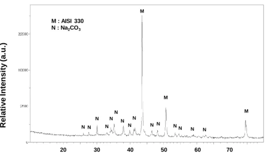
coating was characterized by XRD and it was found that sodium hydroxide reacts with carbon dioxide present in ambient air to form sodium carbonate Na2CO3 (ICDD 18-1208)figure 1. In
the following, the coating will be considered as composed of Na2CO3. During oxidation,
Na2CO3 decomposes at 856 °C to form Na2O and this compound can react with the oxides
6
oxidation only show the presence of the autenitic structure (ICDD 03-1209) labeled as M on
figure 1.
3 Results
3.1 Kinetics
Figure 2 shows the mass gain curves obtained after 48h oxidation on the AISI 330 Alloy. A comparison is made between blank and Na2CO3 coated specimens. Kinetic results show that
the mass gains registered on blank specimens are higher (kp = 1.4 10-12 g2 cm-4 s-1) compared
to the coated specimens (kp = 0.58 10-12 g2 cm-4 s-1).
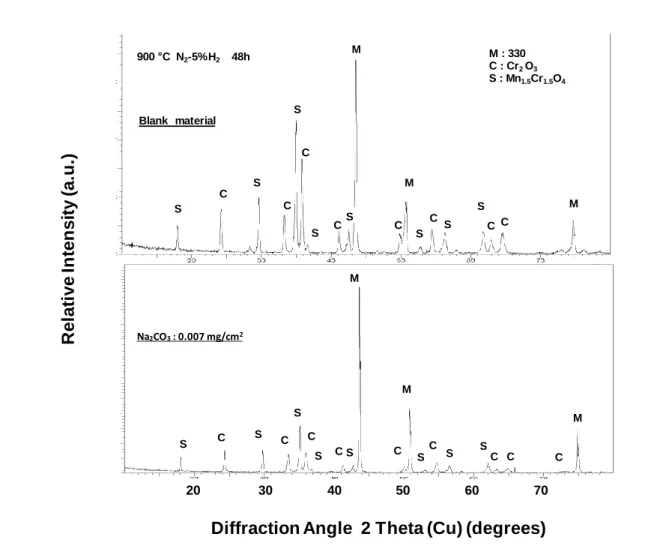
Figure 3 exhibits XRD patterns obtained on the AISI 330 alloy (niobium free) after 48 h oxidation at 900 °C. The oxide scale is composed of Mn1.5Cr1.5O4 (ICDD 33-0892) and Cr2O3
(ICDD 38-1479) on the blank material and on the specimen coated with 7 10-3 mg cm-2
Na2CO3. No cristobalite is detected on the XRD patterns indicating that the silica scale is
amorphous on blank specimens and that no silicon containing oxides are formed on coated specimens. XRD patterns also confirm that the oxide scale is thinner on coated specimens.
3.2 Oxide scale structure
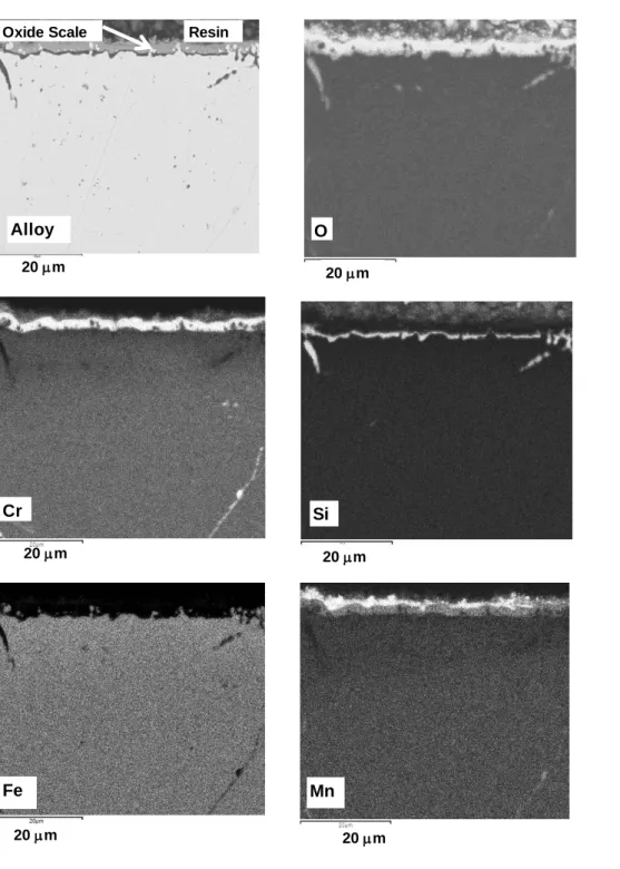
Figure 4 shows the SEM cross section obtained on the blank AISI 330 specimen oxidized 48
h at 900 °C in N2-5vol.% H2. It indicates that on the niobium free alloy AISI 330, silicon is
free to diffuse and forms an amorphous silica layer at the internal interface. The amorphous state of the silica layer was analytically shown by XRD results given above (figure 3). The
7
oxide scale is also clearly composed of an external Mn1.5Cr1.5O4 layer and a Cr2O3 layer
between silica and manganese chromite.
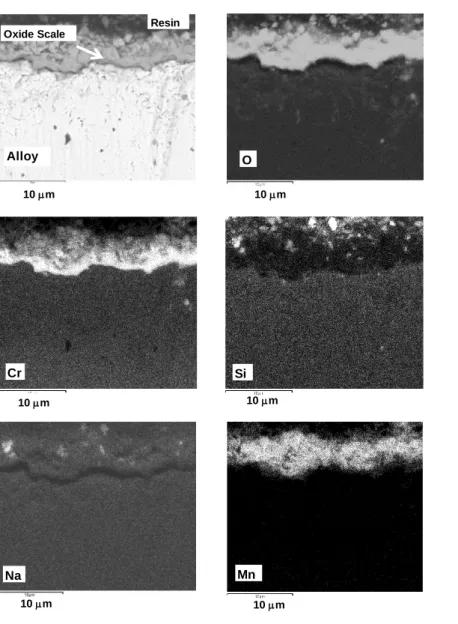
Figure 5 exhibits the SEM cross section obtained on the Na2CO3 coated AISI 330 specimen (7
10-3 mg cm-2) oxidized 48 h at 900 °C in N2-5vol.% H2. It shows that silicon and sodium are
located at the same place inside the scale showing that sodium traps silicon and hinders the silica scale formation.
4 Discussion
The study of niobium-free AISI 330 alloys oxidation has been performed to better understand the chemical interactions between sodium and silicon. The present work has focussed on the influence of sodium coatings (Na2CO3) on the AISI 330 oxidation during 48 h, at 900 °C in
N2-5vol.% H2 gaseous environments. The exact role of sodium on the oxidation behaviour of
the alloy will be discussed by a comparison with niobium containing the AISI 330Cb alloy oxidized in the same conditions. [14]
Owing to the specific oxidizing conditions exposed in the present work some aspect will be also discussed. We will give some explanations concerning the effect of low oxygen partial pressure condition on the oxidation mechanism. Secondly, the expected role of silicon on the alloy oxidation will be examined.
8
4.1 Oxidation under low oxygen partial pressure conditions
Our results show that during the AISI 330 oxidation at 900 °C in N2-5vol.% H2, the 15 ppm
oxygen partial pressure allows the alloying elements oxidation. This oxygen content is high enough to induce the substrate oxidation because thermodynamic data indicate that only p(O2)
= 10-22 atmosphere is necessary to oxidised chromium at 900 °C. Thermodynamic data also
indicate that p(O2) = 10-30 atm. is enough to oxidised silicon at 900 °C. XRD results have
shown that at 900 °C the oxide scales are mainly composed of Mn1.5Cr1.5O4 and Cr2O3. The
relatively high Mn1.5Cr1.5O4 peaks intensities indicate that this phase is present at the external
interface (figure 4). Our results also show that manganese diffuses to the scale external interface in all cases. This phenomenon was reported by other authors.[15-17] Mn1.5Cr1.5O4 is
sometimes considered as non-protective because it presents a porous structure and a bad adherence. [16, 18] Other authors pointed out that Mn1.5Cr1.5O4 located at the external
interface, could reduce the conversion of Cr2O3 into a CrO3 volatile oxide above 1000 °C.
[19-21]
Our XRD and SEM results indicate that after oxidation of the blank AISI 330 specimen, the scale is composed of Mn1.5Cr1.5O4 and Cr2O3. Present results show that the silica scale
formation is promoted by low oxygen containing gaseous environments such as N2-5vol.% H2
as demonstrated in a previous work. [10]
The effect of a low oxygen environment can be compared to other works describing the effect of surface coatings limiting the oxygen access to the alloy surface. [10] Some authors have
9
shown that an yttrium sol-gel coating promotes a continuous silica scale formation at the internal interface on the alloy AISI 304 due to a limited access of the oxygen to the metallic surface. [22] Then, silica hinders the iron oxidation and the formation of non-protective iron oxides.[23] Even though the alloy AISI 330Cb contains 1.55 wt.% silicon, results show that no continuous silica scale formation was observed after oxidation in air, at 900 °C. Some scale spallation, observed on uncoated specimens, has also been explained by the presence of the high silicon amount in the alloy. [24] Douglass studied the Ni-2.05Si and Ni-4.45Si oxidation in oxygen for 18 hr in the temperature range 600-1000 °C. [25] This author proposed that the low silicon content alloy exhibited extensive internal oxidation and that the higher-silicon alloy formed a continuous layer of silicon-rich oxide.
Nakakubo has given oxidation results obtained on Fe-Si and Fe-Cr alloys at 850 °C. This author calculated the boundary conditions between internal and external oxidation based on the kinetic theory of the internal oxidation. [26] Onishi has also calculated the conditions at the boundary between internal to external oxidation of Si containing steels (Fe-Si alloys) at 850 °C. [27] This author has demonstrated that under low oxygen potential a very thin SiO2
layer forms on the alloy surface because the diffusion rate of silicon is relatively high compared with that of oxygen. It is then concluded that internal oxidation occurs in a restricted oxygen partial pressure range and is limited to silicon concentrations below 1 wt.%. The oxygen partial pressure range, in which internal oxidation can occur, decreases with increasing silicon content. When the silicon content increases, external silicon oxidation should occur.
In the present work, it is observed that under low oxygen potentials, the high silicon concentration in the AISI 330 alloy permits the rapid formation of a silica scale on the alloys surface because the diffusion rate of silicon is relatively high compared with that of oxygen
10
4.2 Silicon effect on the alloy oxidation
Figure 3 shows XRD patterns obtained on the AISI 330 alloy (niobium free) after 48 h oxidation at 900 °C, in N2-5%H2. The oxide scale is composed of Mn1.5Cr1.5O4 and Cr2O3 on
the blank material and on the specimen coated with 7 10-3 mg cm-2 Na2CO3. No silica is
detected on the XRD patterns due to its amorphous state.
The effect of silicon on the oxidation process has already been examined on chromia forming alloys. It generally acts as a protective element. Even though too much silicon is detrimental for the steels mechanical properties its addition generally improves the oxidation and carburization resistance. [28] Some authors stated that silicon segregates at the oxide/alloy interface and blocks the iron cationic diffusion. [29-31] Silicon is present as a silica film, which lowers the steel oxidation rate. The high silicon oxygen affinity permits its internal oxidation, developing SiO2 precipitates close to the internal interface. [16] Then, it is reported
that silica acts as a diffusion barrier and leads to the keying of the chromia scale to the substrate. [32, 33] Silica will also lower the porosity at the internal interface acting as vacancies sinks. [34] Silicon reduces the amount of non-protective iron oxides inside the scale. [23] It also hinders the iron rich nodule formation. [30] It has been proposed that during the oxidation of a AISI 304 stainless steel between 900 et 1000 °C, 0.88 wt.% silicon leads to the formation of a chromia scale, even at 1000 °C. [35] Nevertheless, it appears that high silicon content induces more scale spallation between the alloy and the silica scale or at the silica/chromia interface. [30] It is the reason why silicon is generally not added at more than 1 weight %. One should also take care that the chromium presence is necessary to avoid the fayalite Fe2SiO4 formation, which acts as a very poor diffusion barrier. [23] According to
11
chromium content increases. [36] Concerning the effect of higher silicon additions, Li compared the oxidation behaviour at 1000 °C of Ni-based alloys with and without about 2.7 wt.% Si additions. [37] From oxidation results, silicon addition improves oxidation resistance by forming a continuous SiO2 layer at the scale/alloy interface, which resulted in decreased
oxidation kinetics. The cast alloys, with silicon addition, also showed larger average effective inter-diffusion coefficients of chromium compared to the cast alloys without silicon addition. Therefore, the silicon addition assisted in the establishment and re-formation of a chromia scale during oxidation.
On commercial alloys a discontinuous distribution of SiO2 precipitates near the scale/alloy
interface was found to be beneficial to cyclic oxidation resistance due to a keying effect. The formation of an amorphous silica inner layer was effective in reducing the oxidation rate of a Fe-9%Cr alloy to about half that of a Si-free steel at 700 °C, in steam, when alloyed with 0.5% Si. [38] Ishitsuda carried out a detailed study on the effect of Si additions between 0.06% and 0.49% on the 9Cr steel in the temperature range 500-700 °C in high pressure (35 MPa) steam, and concluded that silicon was most effective in reducing the oxidation rate at the highest temperature tested and at the highest silicon content, where rates were reduced to 50% of that observed with the low silicon alloy. [39] In Ueda’s work the establishment of a complete silica layer was responsible for the protective behaviour at high test temperatures.
[40, 41]
In the present work kinetic results (figure 2) show that the silica scale obtained on blank specimens induces a higher mass gain compared to Na2CO3 coated specimens. Silicon
oxidation can contribute to this higher mass gain. It is difficult to conclude about the effect of silica on the alloy oxidation rate. To answer such a question, it should be interesting to compare the AISI 330 alloy oxidation with a silicon free alloy to have an indication about the protective role of silicon.
12
Figure 4 shows the SEM cross section obtained on the blank AISI 330 specimen. It indicates
that on the niobium free alloy AISI 330, silicon has diffused in the alloy and forms an amorphous silica layer at the internal interface. The oxide scale is also clearly composed of an external Mn1.5Cr1.5O4 layer and a Cr2O3 layer between silica and manganese chromite. Figure
5 exhibits the SEM cross section obtained on the Na2CO3 coated AISI 330 specimen (7 10-3
mg cm-2) oxidized 48 h at 900 °C in N2-5vol.% H2. It shows that silicon and sodium are
located at the same place inside the scale showing that sodium reacts with silicon and hinders the silica scale formation. Former studies have described the effect of sodium salts on the high-temperature oxidation of alloys. Sodium sulphate and sodium chloride generally lead to accelerated oxidation of chromium and hot corrosion processes. [11, 12] Sodium carbonate coated Nickel-base alloys oxidised in air at 900 °C also show fluxing reactions but the morphology of the scales show less perturbation compared to other sodium salts. [13] In the present work, it is then proposed that the presence of a very low sodium carbonate coating (7 10-3 mg.cm-2) does not lead to a higher oxidation rate at 900 °C in N2-5vol.% H2.
4.3 Niobium-silicon interactions
A previous work has shown that during the AISI 330Cb oxidation at 900 °C in N2-5vol.% H2,
the 15 ppm oxygen partial pressure allows the alloying elements oxidation. On AISI 330Cb alloys, a SiO2 cristobalite subscale is formed when a low amount of Na2CO3 is present on the
surface. It has been experimentally demonstrated that sodium combines with niobium to form NaNbO3. Then, sodium has no detrimental effect because this element is not free to induce
glass formation. NaNbO3 alsohinders silicon dissolution in Nb3Ni2Si intermetallic due to the
niobium consumption in the alloy close to the internal interface. Then, silicon is free to diffuse in the alloy and generates silica at the oxide/alloy interface. [14]
13
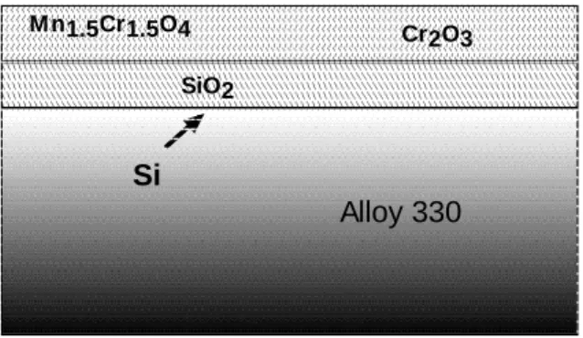
In the present work, it then appears that on the blank AISI 330 alloy, no niobium is available to combine with silicon. Then, silicon is free to diffuse in the alloy and forms an amorphous silica scale as schematically described on (figure 6). This amorphous silica scale is not detectable by XRD (figure 3) but is clearly observed on the SEM cross section (figure 4).
During the AISI 330 Na2CO3-coated alloy oxidation, it should be remembered that no
niobium is present in the substrate. Then, it is observed that no reaction between niobium and sodium (to form NaNbO3) could occur as described on (figure 7). As shown on figure 5,
sodium is free to react with silicon and forms glass particles incorporated inside the scale. These glass particles are also undetectable by XRD due to their amorphous state (figure 3).
It then appears that, on a AISI 330 niobium free alloy, an amorphous silica scale is formed after the blank material oxidation. It indicates that no niobium intermetallic traps silicon in the AISI 330 alloy and silicon is free to form silica. On Na2CO3 coated AISI 330 specimens, no
silica scales are formed because niobium is not present to trap sodium in a NaNbO3
compound. Then, silicon combines with sodium to form glass particles and the substrate is not able to form a silica scale at the internal interface. It obviously implies that the coating amount will be low enough to avoid any detrimental sodium carbonate effect on the surface.
14
The present work has shown the influence of sodium carbonate coatings on the austenitic AISI 330 (Fe-34Ni-23Cr-1.55Si) oxidation at 900 °C. The low oxygen containing N2-5vol.%
H2 gaseous environment was used to simulate industrial heat treatment conditions. Results
confirm that SiO2 formation is promoted by low oxygen containing gaseous environments and
the high alloy silicon content.
On this niobium-free alloy an amorphous silica scale is formed after the blank material oxidation. It indicates that silicon is free to diffuse in the alloy and form a SiO2 scale.
On Na2CO3 AISI 330 coated specimens, no silica scale is formed because niobium is not
present to trap sodium and form NaNbO3. Then, silicon combines with sodium to form
amorphous glass particles.
A comparison has been performed with the work performed on an AISI 330Cb niobium-containing alloy in the same oxidizing conditions. It has been reported that, on the AISI 330Cb alloy, a SiO2 cristobalite subscale is formed when a low amount of Na2CO3 is present
on the surface.
We can then conclude that sodium carbonate coatings could only favour silica formation on niobium containing alloys due to a reaction between Na and Nb.
REFERENCES
[1] G.M. Smith, D.J. Young, D.L. Trimm, Oxid. Met. 1982, 18, 229. [2] J. Hemptenmacher, H.J. Grabke, Werkst. Korros. 1983, 34, 333.
15
[4] G.R. Holcomb, D.E. Alman, Scripta Mater. 2006, 54, 1821. [5] B. Gleeson, M.A. Harper, Oxid. Met. 1998, 49, 373.
[6] R. Stevens, Oxid. Met. 1979, 13, 353.
[7] H. Buscail, C. Issartel, C.T. Nguyen, S. Perrier and A. Fleurentin, Matériaux &
Techniques 2010, 98, 209.
[8] H. Buscail, C. Issartel, F. Riffard, R. Rolland, S. Perrier, A. Fleurentin, C. Josse, Appl.
Surf. Sci. 2011, 258, 678.
[9] C. Issartel, H. Buscail, C.T. Nguyen, A. Fleurentin, Mater. Corros. 2010, 61, 929.
[10] H. Buscail, C. Issartel, F. Riffard, R. Rolland, S. Perrier, A. Fleurentin, Corros. Sci.
2012, 65, 535.
[11] L. Couture, F. Ropital, F. Grosjean, J. Kittel, V. Parry, Y. Wouters, Corros. Sci. 2012,
55, 133.
[12] B.P. Mohanty, D.A. Shores, Corros. Sci. 2004, 46, 2893. [13] M. Misbahul Amin, Thin Solid Films 1997, 299, 1.
[14] H. Buscail, C. Issartel, F. Riffard, R. Rolland, C. Combe, P.-F. Cardey, Oxid. Met. 2017,
87, 837.
[15] H.B. Grübmeier, A. Naoumidis, H.A. Schulz, J. Vac. Sci. Technol. 1986, A4, 2565. [16] M. Landkof, A.V. Levy, D.H. Boone, R. Gray, E. Yaniv, Corros. Sci. 1985, 41, 344. [17] I. Saeki, T. Saito, R. Furuichi, H. Konno, T. Nakamura, K. Mabuchi, M. Itoh, Corros.
Sci. 1998, 40, 1295.
[18] N. Hussain, K.A. Shahid, I.H. Khan, S. Rahman, Oxid. Met. 1995, 43, 363. [19] C.S. Tedmon, 1966, 113, 766.
[20] G. Ben Abderrazik, G. Moulin, A.M. Huntz, Oxid. Met. 1990, 33, 191. [21] H.M. Tawancy, Oxid. Met. 1996, 45, 323.
16
[22] F. Riffard, H. Buscail, E. Caudron, R. Cueff, C. Issartel and S. Perrier, J. Mater. Sci.
2002, 37, 3925.
[23] F.J. Pérez, M.J. Cristobal, M.P. Hierro, F. Pedraza, Surf. Coat. Technol. 1999, 120-121, 442.
[24] P.Y. Hou, J. Stringer, J. de Phys. IV 1993, C9, 231.
[25] D.L. Douglass, P. Nanni, C. De Asmundis, C. Bottino, Oxid. Met. 1987, 28, 309. [26] S. Nakakubo, M. Takeda, T. Onishi, Mater. Sci. Forum 2011, 696, 88.
[27] T. Onishi, S. Nakakubo, and M. Takeda, Mater. Trans. 2010, 51, 482.
[28] F. Armanet, J.H. Davidson, P. Lacombe, Les aciers inoxydables, B. Baroux, G. Beranger, Les Editions de Physique, Les Ulis, France, 1990.
[29] A.M. Huntz, Mater. Sci. Engi. 1995, A201, 211. [30] S.N. Basu, G.J. Yurek, Oxid. Met. 1991, 36, 281.
[31] H.E. Evans, D.A. Hilton, R.A. Holm, S.J. Webster, Oxid. Met. 1983, 19, 1. [32] S. Seal, S.K. Bose, S.K. Roy, Oxid. Met. 1994, 41, 139.
[33] R.N. Durham, B. Gleeson, D.J. Young, Oxid. Met. 1998, 50, 139. [34] H. Nagai, Mater. Sci. Forum 1989, 43, 75-130.
[35] A. Paúl, S. Elmrabet, L.C. Alves, M.F. Da Silva, J.C. Soares, J.A. Odriozola, Nucl. Instr.
and Meth. in Phys. Res. 2001, B 181, 394.
[36] F.H. Stott, G.C. Wood, J. Stringer, Oxid. Met. 1995, 44, 113. [37] B. Li, B. Gleeson, Oxid. Met. 2006, 65, 101.
[38] T. Ishitsuka, Y. Inoue, H. Ogawa, Oxid. Met. 2004, 61, 125.
[39] M. Ueda, Y. Oyama, K. Kawamura, T. Maruyama, Mater. High Temp. 2005, 22, 79. [40] M. Ueda, M. Nanko, K. Kawamura, T. Maruyama, Mater. High Temp. 2003, 20, 109. [41] H. Buscail, S. El Messki, F. Riffard, S. Perrier, C. Issartel, Oxid. Met. 2011, 75, 27.
17
Figure 1: XRD pattern obtained on the AISI 330 alloy coated with 1.401 mg cm-2 NaOH showing that it reacts with CO2 present in air to form Na2CO3.
R el ati ve In ten si ty (a. u .)
Diffraction Angle 2 Theta (Cu) (degrees)
M M M S S S S S S S C C C C B B B A A A A A A A A A S 20 30 40 50 60 70 M : AISI 330 N : Na2CO3 M M M N N N N N N N N N N N NN N N 0 10 20 30 40 50 60 Dm/S (mg.cm-2) Dm/S (mg.cm-2) t/h Blank AISI 330 Coated AISI 330
18
Figure 2: Mass gain curves obtained after 48h oxidation on the AISI 330 Alloy. Comparison
of blank and Na2CO3 coated specimens.
Figure 3: XRD pattern obtained on the AISI 330 alloy (niobium free) after 48 h oxidation at
900°C, in N2-5%H2. Oxides formed on the blank material and on the specimen coated with 7
10-3 mg cm-2 Na2CO3 (no silica is detected on patterns).
R el ati ve In ten si ty (a. u .)
Diffraction Angle 2 Theta (Cu) (degrees)
M S S S S S C C C C C C C A S S M M M M S S S S S S S I I I C C C C C C C S S C C S A A S C 20 30 40 50 60 70 M Na2CO3: 0.007 mg/cm2 M M S S S S S S S C C C C C C C C C S M M M Blank material 900 C N2-5%H2 48h M : 330 C : Cr2 O3 S : Mn1.5Cr1.5O4 S S S S S S S S C C C C C C C C
19
Figure 4. SEM cross sections obtained on the blank AISI 330 specimen oxidized 48 h at 900
°C in N2-5vol.% H2 (BSE Image x 2000). On the niobium free AISI 330 alloy, silicon is free
to diffuse and forms an amorphous silica layer at the internal interface.
20 m
20 m
20 m 20 m
Oxide Scale Resin
Alloy 20 m Cr O 20 m Si Mn Fe
20
Figure 5. SEM cross sections obtained on the Na2CO3 coated AISI 330 specimen (7 10-3 mg
cm-2) oxidized 48 h at 900 °C in N2-5vol.% H2 (BSE Image x 5000). Silicon and sodium are
located at the same place inside the scale showing that sodium traps silicon and hinders the silica scale formation.
10 m 10 m 10 m 10 m 10 m Oxide Scale Resin Alloy O 10 m Cr Si Na Mn
21
Figure 6. Schematic drawing showing the amorphous SiO2 scale formation on the AISI 330
(niobium free) alloy oxidized at 900 °C, during 48h, in N2-5vol.% H2.
Figure 7. Schematic drawing showing the sodium silicon interaction on the coated AISI 330
(niobium free) alloy oxidized at 900 °C during 48h in N2-5vol.% H2.
Table 1. Alloys composition (weight %).
Wt. % Fe Ni Cr Si Nb Mn C P S AISI 330 Bal. 34.76 18.82 1.31 0.03 1.40 0.05 0.019 0.0004 AISI 330Cb Bal. 34.41 22.87 1.55 0.97 0.72 0.05 0.012 0.002 M n1.5Cr1.5O4 SiO2 Si Cr2O3 Alloy 330 Glass (Na) Mn1.5Cr1.5O4 Si Cr2O3 Alloy 330
22
Graphical Abstract
On blank AISI 330, amorphous SiO2 formation is due to silicon diffusion from the alloy to the
internal interface. On Na2CO3 coated specimens, no silica scales are formed because niobium
is not present to combine with sodium. Then, silicon reacts with sodium to form amorphous glass particles. Sodium carbonate coatings only favour silica formation on niobium containing alloys due to a possible neutralisation of sodium by niobium.
Glass (Na) Mn1.5Cr1.5O4
Si
Cr2O3