HAL Id: in2p3-00818756
http://hal.in2p3.fr/in2p3-00818756
Submitted on 12 Jul 2013
HAL is a multi-disciplinary open access
archive for the deposit and dissemination of
sci-entific research documents, whether they are
pub-lished or not. The documents may come from
teaching and research institutions in France or
abroad, or from public or private research centers.
L’archive ouverte pluridisciplinaire HAL, est
destinée au dépôt et à la diffusion de documents
scientifiques de niveau recherche, publiés ou non,
émanant des établissements d’enseignement et de
recherche français ou étrangers, des laboratoires
publics ou privés.
Assembling, Testing and Installing the SPIRAL2
Superconducting LINAC
P.E. Bernaudin, R. Ferdinand, P. Bosland, G. Olry, Y. Gómez Martínez
To cite this version:
P.E. Bernaudin, R. Ferdinand, P. Bosland, G. Olry, Y. Gómez Martínez. Assembling, Testing and
Installing the SPIRAL2 Superconducting LINAC. IPAC 13 - The 4th International Particle Accelerator
Conference, May 2013, Shanghai, China. Joint Accelerator Conferences Website, pp.3752-3754, 2013.
�in2p3-00818756�
ASSEMBLING, TESTING AND INSTALLING THE SPIRAL2
SUPERCONDUCTING LINAC
P.-E. Bernaudin, R. Ferdinand, GANIL, Caen, France
P. Bosland, CEA/Irfu, Saclay, France
G. Olry, IPNO, Orsay, France
Y. Gómez Martínez, LPSC, Grenoble, France
Abstract
Assembly and tests of the SPIRAL2 superconducting linac's components are now proceeding smoothly. Cryomodules are being processed in CEA Saclay and IPN Orsay, inter-cryomodules "warm" sections in GANIL. While installation of the accelerators components is going on in the new SPIRAL2 building in Caen, installation of the cryomodules will begin during the last quarter of 2013. The latest results of the cryomodules tests as well as the installation strategy are depicted in this paper.
INTRODUCTION
The driver of the GANIL's SPIRAL2 Project [1] consists of two high performance ECR sources, a RFQ, and the superconducting (SC) linac. The driver is also asked to provide all the energies from 2 MeV/u to the maximum designed value.
The SC linac is composed of low E and high E cryomodules, each one including one E=0.07 cavity or two E=0.12 cavities respectively.
This paper describes the status of the construction of the superconducting linac and the strategy for its installation in the new SPIRAL2 building.
ASSEMBLING AND TESTING
CRYOMODULES
Low E cryomodules are developed, assembled and tested by CEA/Irfu at Saclay, and high E cryomodules by IPN Orsay. Both types of cavities are equipped with the same 40 kW power coupler, developed, assembled and conditioned in a third laboratory, LPSC Grenoble.
Cryomodules A
The E=0.07 cryomodule (type A) design has been described in this reference [2].
All E=0.07 cavities have now been qualified in vertical cryostat and have reached the required specifications: less than 10 W of dynamic losses at nominal, 6.5 MV/m accelerating gradient (see Fig. 1). The 13th, spare cavity is being treated following beam vacuum leaks.
Assembly and test of these cryomodules are now proceeding routinely. Four cryomodules have been successfully RF tested at 4 K. Two of those cryomodules have been completely qualified; two other ones have been tested and only require some alignment corrections. Two more fully assembled cryomodules are awaiting cold test, while two other ones are in different stages of assembly (beam vacuum being sealed).
Figure 1: Q0 vs. Eacc curves of E=0.07 cavities.
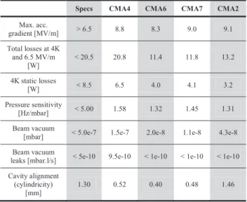
Table 1: Measured Performances of E=0.07 Cryomodules already Tested
Specs CMA4 CMA6 CMA7 CMA2
Max. acc. gradient [MV/m] > 6.5 8.8 8.3 9.0 9.1 Total losses at 4K and 6.5 MV/m [W] < 20.5 20.8 11.4 11.8 13.2 4K static losses [W] < 8.5 6.5 4.0 4.1 3.2 Pressure sensitivity [Hz/mbar] < 5.00 1.58 1.32 1.45 1.31 Beam vacuum
[mbar] < 5.0e-7 1.5e-7 2.0e-8 1.1e-8 4.3e-8 Beam vacuum
leaks [mbar.l/s] < 5e-10 9.5e-10 < 1e-10 < 1e-10 < 1e-10 Cavity alignment
(cylindricity) [mm]
1.30 0.52 0.40 0.48 1.46
RF cold tests of the cryomodules show good performances (see table 1). Previous field emission problems caused admittedly by dust pollution have been eradicated, thanks to optimised preparation procedures. Notice that, contrary to what is usually done, cavities are not HPR rinsed anymore between the vertical cryostat test and cryomodule assembly in the clean room; between these two steps, the cavity is refilled with filtered air to avoid contamination. None of the cryomodules prepared this way failed the RF qualification tests.
Cryomodules B
The E=0.12 cryomodule (type B) design has been described in these references [3][4].
THPWO001 Proceedings of IPAC2013, Shanghai, China
ISBN 978-3-95450-122-9 3752 Copyright c○ 2013 by J A CoW — cc Cr eati v e Commons Attrib ution 3.0 (CC-BY -3.0) 04 Hadron Accelerators A08 Linear Accelerators
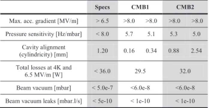
As for cryomodules A, contamination problems have been solved. Two cryomodules have been assembled. One of them is qualified, the other one showed good RF performances; cavities have reached the nominal gradient and total cryogenic losses are on the safe side (lower than 30 W) but one cavity is misaligned which could lead to partial disassembly (no intervention on beam vacuum is foreseen).
Table 2: Measured Performances of E=0.12 Cryomodules already Tested
Specs CMB1 CMB2
Max. acc. gradient [MV/m] > 6.5 >8.0 >8.0 >8.0 >8.0 Pressure sensitivity [Hz/mbar] < 8.0 5.7 5.1 5.3 5.0
Cavity alignment
(cylindricity) [mm] 1.20 0.16 0.34 0.88 2.54 Total losses at 4K and
6.5 MV/m [W] < 36.0 29.5 32.0 Beam vacuum [mbar] < 5.0e-7 <6.0e-8 <6.0e-8 Beam vacuum leaks [mbar.l/s] < 5e-10 < 1e-10 < 1e-10
Main concern was the Cold Tuning System (CTS), which showed what we called “negative backlash”: upon changing action direction, frequency variation was not
changing accordingly until several dozens of Hertz. Extensive tests at room temperature correlated this effect with very small lateral movement of the plunger inside the cavity upon any direction change. The guiding columns have been optimized to ensure these movements are directed along the cavity axis. This suppressed the phenomenon, as confirmed by latest 4K tests of the cryomodules. On the other hand, this rotation of the plunger system and some observed defect on the plunger surface led us to test in vertical cryostat all cavities equipped with the plunger in the proper orientation.
Power Couplers
The power coupler design has been described in this reference [5]. Both cryomodules share the same power coupler with two different external conductor length, in order to provide the coupling differences.
Improvement of the preparation and conditioning procedures, ranging from electropolishing the antenna to seemingly minor aspects like the orientation of the coupler during clean room assembly, provided good results: conditioning time both on the test bench in Grenoble and in the cryomodules in Saclay and Orsay was significantly reduced. Coupler conditioning up to 40 kW (open circuit conditions) on the dedicated bench in Grenoble is now shorter than two days.
In the meantime, it was discovered that the EPDM seals of the valves used on the power coupler pumping port and warm sections were unacceptable, outgasing a significant mass flow of heavy elements. In order to reduce the risks of contamination of the cavities, and to avoid loss of time with the supplier, the valves not yet assembled on the cryomodules were baked in Grenoble, reducing
significantly the partial pressure of masses above 45 (see Fig. 2).
Figure 2: Outgasing of EPDM valves used on the power couplers before and after baking. Blue zone show pollutants above specifications.
Inter-cryomodules Warm Sections
The warm section design required a difficult consensus to allow the insertion of a number of elements in the short available space: two quadrupoles for transverse focusing, steering magnets, one BPM for beam position, transverse matching and phase measurements, one longitudinal beam extension monitor, and the pumping and vacuum diagnostics system.
Figure 3: Inter-cryomodules warm sections during clean room assembly (left) and on alignement bench (right).
Assembly work on the inter-cryomodules warm sections started during summer 2012 (see Fig. 3). Assembly of all components connected to beam vacuum is performed in an ISO5 clean room in Saclay by the GANIL team.
Proceedings of IPAC2013, Shanghai, China THPWO001
04 Hadron Accelerators A08 Linear Accelerators
ISBN 978-3-95450-122-9 3753 Copyright c○ 2013 by J A C oW — cc Cr eati v e Commons Attrib ution 3.0 (CC-BY -3.0)
Assemblies were stopped after four sections when it was discovered that the EPDM seals of the gate and angle valves were outgasing heavy elements. The flow rate was so high that it limited the vacuum in the chambers above 2e-8 mbar (specifications: 1e-9 mbar without beam). Assembly is now restarting from scratch after the manufacturer changed all seals and cleaned the valves according to clean room assembly requirements. EPDM seals were changed to Viton ones after cross-checking the integrated radiation doses requirements for the linac.
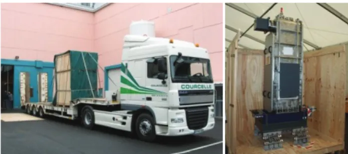
Figure 4: Transportation test of the cryomodule CMA2 from Saclay to GANIL. Right picture shows the cryomodule inside his crate, fixed on its damping support.
INSTALLING THE SUPERCONDUCTING
LINAC
Transportation
Transportation of the cryomodules (250 km by road) from Saclay and Orsay to GANIL has been identified as being a critical operation. Therefore one transportation test has been recently organised. During March 2013, one up-to-specifications, low E cryomodule was transported from Saclay to GANIL, unloaded in GANIL, then loaded again on the truck and transported back to CEA Saclay for tests (see Fig. 4). Shock sensors have recorded all events during the whole transportation. As expected, strongest shocks happen during loading/unloading phases. They stay below 5 g, well under the power coupler limits (10 g in the horizontal plane). Damping system having proved satisfactory will be used for all cryomodules transportations.
Table 3: Performances of E=0.07 Cryomodule CMA2 before and after Transportation
Specs before after
Max. acc. gradient [MV/m] > 6.5 7.8 9.1 Total losses at 4K [W] < 20.5 15.4 13.2 X-rays at nominal gradient [PSv/h] 730 9
Alignment of cavity inside the cryomodule has been checked before and after transportation. No movement was recorded.
After transportation the cavity was once again cold tested in order to verify that performances were not altered. Performances were slightly better after transportation, with reduced field emission (see table 3).
In view of all these results, method and tooling for transportation are qualified and will be used similarly for all 19 cryomodules; cryomodules type A will be transported two at a time, type B ones only one by one.
Installation
Installation of the valve boxes platform in the linac tunnel already started. In order to speed up operations, installation of the cryomodules and warm sections will start before all cabling and tubing operations are completed. Nevertheless, a high standard of cleanliness will be kept in the tunnel at any time in order to avoid any contamination problem.
After the linac supports, which will soon be positioned and aligned inside the tunnel, cryogenic components (helium heaters, valves boxes) will be installed, followed by the warm sections and finally cryomodules will be positioned as they become available.
The most critical step of the linac installation is the connection between inter-cryomodules warm sections and cryomodules. Cavities are being kept under static vacuum (vacuum level being checked regularly and kept below a 0.1 mbar threshold), and the sealing face of the beam valves are kept dust-free by covers put during the clean room assembly phase. On the other side, warm sections stay at atmospheric pressure (but dust-free sealed). Connection will be performed under a mobile, ISO5 laminar flow, specially designed to fit inside the very constraint space between two cryomodules and under the valves box support platform. Meticulous cleaning and particles counts will ensure that the environment is clean enough to perform the connection operation, which is itself very delicate: a Helicoflex™ seal shall be inserted and sealed in a very tight space. This connection has been tested in CEA Saclay with an empty cryomodule.
The whole procedure to be implemented for this connection will be tested on a single cryomodule (high E) and warm section in IPN Orsay.
Start up
Reception tests should start when utilities of the building become operational, which is expected first half of 2014. First cool down of the linac is expected before the end of 2014, with the first particle on the beam dump for Christmas.
REFERENCES
[1] http://www.ganil-spiral2.eu/?set_language=en and http://pro.ganil-spiral2.eu/spiral2/what-is-spiral2.
[2] P.-E. Bernaudin & al., “Design of the low beta, quarter-wave resonator and its cryomodule for the SPIRAL2 project”, EPAC’04, Lucerne, July 2004.
[3] G. Olry & al., “Development of a beta 0.12, 88 MHz, quarter wave resonator and its cryomodule for the SPIRAL2 project”, SRF’05, Ithaca, July 2005.
[4] H. Saugnac & al., “RF and cryogenic tests of the first beta 0.12 SPIRAL2 cryomodule”, Linac’08, Victoria, September 2008.
[5] Y. Gómez Martínez et al., “Last SPIRAL2 10 kW CW RF coupler design”, Linac’08, Victoria, September 2008.
THPWO001 Proceedings of IPAC2013, Shanghai, China
ISBN 978-3-95450-122-9 3754 Copyright c○ 2013 by J A CoW — cc Cr eati v e Commons Attrib ution 3.0 (CC-BY -3.0) 04 Hadron Accelerators A08 Linear Accelerators