HAL Id: in2p3-00187257
http://hal.in2p3.fr/in2p3-00187257
Submitted on 14 Nov 2007HAL is a multi-disciplinary open access
archive for the deposit and dissemination of sci-entific research documents, whether they are pub-lished or not. The documents may come from teaching and research institutions in France or abroad, or from public or private research centers.
L’archive ouverte pluridisciplinaire HAL, est destinée au dépôt et à la diffusion de documents scientifiques de niveau recherche, publiés ou non, émanant des établissements d’enseignement et de recherche français ou étrangers, des laboratoires publics ou privés.
Electronics and Trigger developments for the Diffractive
Physics Proposal at 220 m from LHC-ATLAS
P. Le Dû, J.-F. Genat, O. Kepka, A. Kupco, C. Royon, T. Tic, V. Vrba
To cite this version:
P. Le Dû, J.-F. Genat, O. Kepka, A. Kupco, C. Royon, et al.. Electronics and Trigger developments for the Diffractive Physics Proposal at 220 m from LHC-ATLAS. Topical Workshop on Electronics for Particle Physics (TWEPP-07), Sep 2007, Prague, Czech Republic. �in2p3-00187257�
Electronics and Trigger developments for the Diffractive Physics Proposal
at 220 m from LHC-ATLAS
P. Le Dû
a, J-F Genat, O. Kepka
b, A. Kupco
b, C. Royon
a, T. Tic
b, V. Vrba
ba
DAPNIA-SPP, Saclay F-91191, Gif-sur-Yvette Cedex, France
b
Institute of Physics, Prague, Na Slovance 2, CZ-182 21 Praha 8, Czech Republik
[email protected]
Abstract
The instrumentation consists of two sets of Roman Pots installed respectively at 216 and 224m on both sides from the ATLAS IP to measure with precision the position (< 10 micrometers) and the timing (< 5ps) of the two back to back diffracted protons tracks. Each Roman Pot is equipped with several planes of Silicon strips detectors read out by a new version of the ATLAS Silicon tracker ABCD readout chip with a longer latency (6.4 microseconds) and fast OR outputs defining a track segment. Theses inputs are to be combined in time with the ATLAS level 1 trigger accept signal. In addition, these tracks are time filtered with a very fast timing detector (MCP-PMT) allowing to constraint further at the level 2 the position of the IP within a one millimetre precision., The description of the electronics and trigger system as well as the various technical issues associated with such challenging experiments (clocks, cabling,, time monitoring) will be presented.
I. I
NTRODUCTIONThe motivation to install roman pot detectors at 220 m within ATLAS is under study [1]. It extends nicely the project of measuring the total cross sections using roman pots at 240 m by measuring hard diffraction at high luminosity in ATLAS in the LHC. It is also complementary to the FP420 project which aims at tagging protons at 420 m. The physics motivation of this project corresponds to different domains of diffraction:
• A better understanding of the inclusive diffraction mechanism at the LHC by studying in detail the structure of pomeron in terms of quarks and gluons as it was done at HERA. Of great importance is also the measurement of the exclusive production of diffractive events and its cross section in the jet channel as a function of jet transverse momentum. Its understanding is necessary to control the background to Higgs signal.
• Look for Higgs boson diffractive production in double pomeron exchange in the Standard Model or super symmetric extensions of the Standard Model. This is clearly a challenging topic especially at low_ Higgs boson masses where the Higgs boson decays in b b and the standard non-diffractive search is possible. We will detail in the following the trigger strategy.
• Sensitivity to the anomalous coupling of the photon by measuring the QED production cross section of W boson pairs. This might be the best way to access the anomalous coupling before the start of the ILC.
• Photo-production of jets.
• Other topics such as looking for stop events or measuring the top mass using the threshold scan method which will depend strongly on the production cross section.
II. T
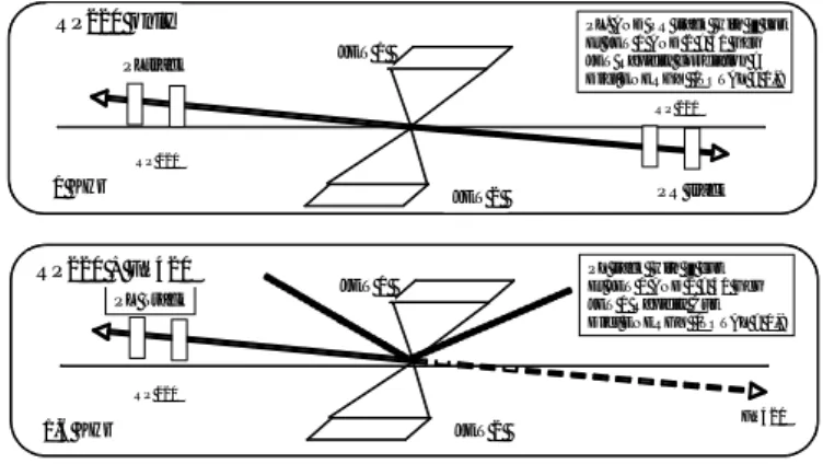
RIGGERThe topology of the typical event to be selected is presented in Figure 1. There are two selection schemes according to the two complementary possibilities of combining either the Roman pot stations at 220 m both sides of the ATLAS IP or one side with one 220 m Roman pot station with the FP420 information arriving only at the Level 2 trigger.
Figure 1: Trigger principle
In the first case we ask for a coincidence between tracks with ξ < 0,01 in the left and right station. This PRETRIGGER signal will have to be merged with ATLAS level 1 Dijet Et trigger > 40 Gev AND a Dijet energy/total >
0,9. A rate of 1kHz is expected. Additional rate reduction would be possible by using the rapidity and azimuthal correlation.
PLtrack
PR track
PL. AND PR track with cut Et JET 1 AND 2 > 40 Gev JET Rapidity correlation ? Dijet ENERGY /TOTAL > 0,9
RP 220
RP 220
JET 1
JET 2
PL Track
PL track with cut Et JET 1 AND 2 > 40 Gev JET 1 Rapidity Cut Dijet ENERGY /TOTAL > 0,9
RP 220 FP420 JET 1 JET 2 RP220 only RP220 + FP420 1 KHz 1,6 KHz
In the second case, it is possible to combine one of the RP220 station (Left or Right) with the FP420 information arriving at L2. In this case, some additional cuts in the Dijet topology are required to reach an equivalent trigger rate of 1,6 kHz.
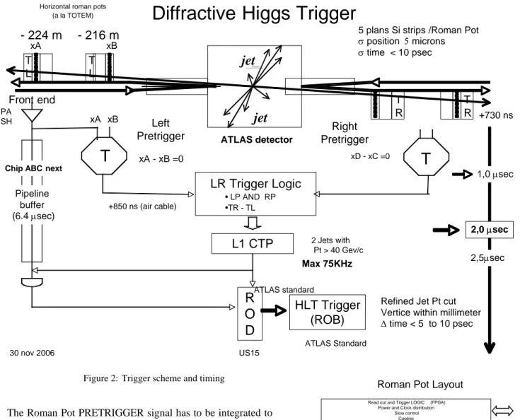
Figure 2: Trigger scheme and timing
The Roman Pot PRETRIGGER signal has to be integrated to the present ATLAS trigger scheme at the L1 (75 KHz maximum rate, 2.5 microseconds latency) and L2/L3 levels as presented in figure 2.
Each of the four Roman pots will have the same hardware configuration consisting of seven silicon edgeless strips detector planes followed by a pixilated timing device. Two Silicon strips planes oriented in the X direction are devoted to the PRETRIGGER. An upgrade version of the ABCNext chip with a fast output is foreseen to be developed to include the L1 trigger. The timing device is made of a MCP-PMT which collects the Cherenkov light produced by the incoming particle across a crystal radiator (Figure 3 ).
At LEVEL 1 a PRETRIGGER is foreseen with two steps Left-Right Tracking using the fast outputs of the silicon strips vertical planes of each Roman pot station. An hodoscope like track segment logic is required on bothleft and right stations prior to be merged as a signal entry in the central Atlas Level 1 (CTP). These signals are time filtered with a few ns gate
provided by associated pixels of the timingdetector. from the roman pots stations.
Figure 3: Roman pot layout
This should be done within the L1 CTP latency of about 2 microseconds leaving around 500ns for the full digital logic, taking into account the particles flight path and transit cables be combined with two jets with a large Pt >20 Gev/c to make the L1 diffractive trigger. A possible implementation of the various electronics functional blocks and cables as well
ATLAS standard
Diffractive Higgs Trigger
Horizontal roman pots (a la TOTEM)
QuickTime™ et un décompresseur sont requis pour visionner cette image.
L1 CTP
+730 ns Front endR
O
D
- 216 m
Left PretriggerLR Trigger Logic
• LP AND RP •TR - TLHLT Trigger
(ROB)
2,5μsec +850 ns (air cable) Max 75KHz Right PretriggerT
T L T RT
2,0 μsec5 plans Si strips /Roman Pot σ position 5 microns σ time < 10 psec Pipeline buffer (6.4 μsec) xA - xB =0 xA xD - xC =0 xB 2 Jets with Pt > 40 Gev/c
Refined Jet Pt cut Vertice within millimeter Δ time < 5 to 10 psec
jet
jet
- 224 m
xA xB ATLAS detector T R T L US15 1,0 μsec PA SHChip ABC next
30 nov 2006
ATLAS Standard
Roman Pot Layout
U Y X X MCP-PMT Light Guide Radiator 8 x 8 Pixels 2,54 x 2,54 cm Beam 4,5 cm Read Out ASIC 64 Ch. FE ASIC (PA,SH,Pipeline) Plus FAST OR
Read out and Trigger LOGIC (FPGA) Power and Clock distribution
Slow control Cooling To Alcove V X X Edgeless Silicon Strips
as the associated timing and data flow are presented in Fig 4. In addition, using the pico-second timing detectors, it would be possible to give a rough estimate of the position of the vertex inside the 6 centimeters collision diamond (200 psec). It is however not yet clear at this stage of the study if this timing information can be fully exploited at this early stage level.
At LEVEL 2, the full digitized information of all the silicon strips planes will allow a precise reconstruction of each track hits with a precision of 5 micrometers. In addition the timing
information can be then fully used in order to isolate the relevant vertex with a precision of the millimeter or better.
Figure 4: Trigger implementation block diagram
III. S
ILICON DETECTORSSilicon detectors are envisaged for the Roman Pots as accurate position sensors. Silicon strips can currently achieve space resolutions down to a few micrometers. A resolution of 10-15 μm is actually required. A timing resolution allowing to identify the beam crossing is also required.
Strips can be implemented as AC or DC coupled sensors depending whether the leakage current can be managed by the readout chip. As the area is small for theses detectors (2cm x 2cm) and a high level of irradiation is not foreseen, the leakage current should be small enough to allow the use of DC detectors. However, there is not a significant extra cost for AC coupled detectors, and this conservative option has been chosen. Silicon detectors have to be sensitive as close as possible to the beam, a dead zone close to their edge of 20-40 μm can be accepted, with the edge at 10 sigmas from the beam, i.e. 0.8mm.
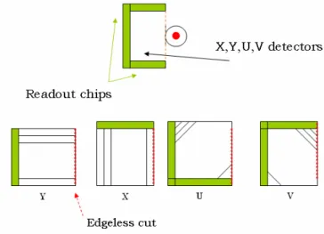
A. Detectors characteristics
Five layers of detectors are planned, two vertical, one horizontal, one at 45 degrees, one at –45 degrees. Pitch can be 50 μm in a first step, 25μm could be used at an extra cost, with pitch adapters to the readout chips whose pitch is presently 50 μm.
Two extra layers of strips with a pitch of 100-200 μm would be used for the trigger.
B. Roman Pots specific requirements
Detectors have to be edgeless to 20-40 μm. CANBERRA has proposed an edge processing allowing to avoid surface currents leading to an undepleted area close to the edge. A dead area less than 30 μm is expected. These detectors are presently manufactured and will be tested at Saclay.
C. Detectors specifications
The following specifications would meet the Roman Pots Silicon detectors requirements.
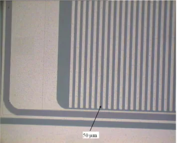
D. Prototypes and first tests
Several companies have been contacted, among them, CANBERRA has delivered four (non-edgeless) detectors prototypes, 128 channels at 50 μm pitch (Figure 5) that are under evaluation at Prague FZU and at Saclay using a VME test stand developed in the context of the ATLAS Silicon Trackers provided by CERN [2], interfaced to the ABCD chips. Figure 6 shows the reverse current from 0 to 220 V biasing voltage for a 0.7cm2 CANBERRA detector measured at The Institute of Physics, Prague, Czech Republik.
Figure 5: Detector geometries
Table 1: Silicon strips edgeless detector specifications
Dimensions 2x2cm2 Pitch 25-50μm AC coupled 10pF/cm > 200V Interstrip cap < 1.5pF Full depletion 60-100V Thickness 300 μm Leakage <50nA/cm2 @200 V Poly resistor > 2Gω
Edgeless (one side) < 40 μm Defective strips < 1% Radiation hardness > 1012 n/cm2 LHC CLK IP
//
Local Logic Detector ASIC Pretrigger logic Read Out Control & MonitoringμCTA crate Shielded Alcove Picosecond CLK 160 MHz Trigger DATA 4,16 Gb/s RO DATA 670 kb/s 20 m Cables FPGA T X X FPGA T X X ATLAS LVL1 CTP ATLAS ROD (LVL2 & DAQ) US 15 Reference clock (Atomic) RP Left Trigger 1Cable 160 MHz CLK (fiber) LHC CLK 2 x 3,2 Gb/s L1 ACCEPT RP Right Trigger 75 KHz DATA 25 Mb/s 4 fiberss
IV.
T
IMINGD
ETECTORSThe timing detectors are necessary at the highest luminosity of the LHC to identify from which vertex the protons are coming from. It is expected that up to 35 interactions occur at the same bunch crossing and we need to identify from which interaction, or from which vertex the protons are coming from.
Figure 6: 50 μm pitch detectors from CANBERRA
Figure 7: Reverse current (0.7 cm2 detector)
A precision of the order of a few mm or 5-10 ps is required to distinguish between the different vertices and to make sure that the diffracted protons come from the hard interactions.Picosecond timing detectors are still a challenge and are developed in a collaboration between Saclay, Stony Brook, the University of Chicago and Argonne National Laboratory formedical and particle physicsapplications. The proton timings will be measured in a crystal of about 2.5 cm located inside the roman pots, and the signal will be read out by Micro-Channel Plates photo-multipliers developed by Photonis.
The space resolution of those detectors should be of the order of a few millimeters since at most two protons will be detected in those detectors for one given bunch crossing at the highest luminosity.
V. T
IMINGD
ETECTORSE
LECTRONICSMCP-PMT detectors are used to achieve picosecond time of flight in order to reconstruct vertices to a 1mm precision. The electronics has to digitize time differences in the range –200 +200 ps without degrading significantly the MCP-PMT detector resolution. Present resolution of 30 ps (Time Transit Spread) has been measured for single photon at the University of Nagoya (Japan). Simulations at the Enrico Fermi Institute (IL USA) of MCP PMTs equipped with segmented anodes [3] predict sub-picosecond performance for 20 photons events, leading to 4 ps TTS, under the same conditions (single photon).
A. Time picking
Time picking optimisation requires a good knowledge of the detector signals, and the associated noise. Techniques to be implemented can be leading edge threshold, multiple threshold, constant fraction (many flavours), pulse sampling and reconstruction. Work is in progress to determine the best trade-off taking into account the available integrated circuit technologies (Silicon-Germanium, Deep Sub-Micron CMOS).
B. Time to digital conversion
Picosecond resolution is targeted at EFI Chicago, see [4] “Development of Front-end Electronics for Picosecond Resolution TOF Detectors” , poster at this workshop by Fukun Tang, using a 250nm SiGe process. A time stretcher with a 200 slopes ratio is planned to expand the picosecond time range to fractions of nanoseconds. Time to digital conversion with 100 ps resolution can be implemented using FPGAs clocked at 250 MHz [5].
C. Implementation
The MCP-PMT is 2” x 2” large. An equal time path printed circuit board links the 64 anodes to four electronics channel, with traces lengths compensating for the time propagation of signals coming from any MCP-PMT location. Signal and ground return constitute a differential pair that couples capacitively to the MCP ground. An analogue card holds four time stretcher chips sending stretched pulses to an upper card housing an FPGA in charge of the 100ps time to digital conversion, all digital controls, and a Phase Locked Loop (PLL) for input clock jitter cleaning to 100-200ps. The time stretcher houses a second PLL at 2 GHz, cleaning the remaining jitter to better than 1ps. All three cards stacked represent a thickness of half an inch.
VI.
C
ONCLUSIONThis project aims at installing Roman pots at 220 m from the ATLAS interaction point. A combination of Silicon detectors and Micro Channel plates photomulipliers provide
both space and time resolution allowing to measure precisely the inclusive diffraction mechanism at LHC as well as exclusive diffractive events, and their cross section in the jet channel as a function of jet transverse momentum whose understanding is mandatory to control the background to Higgs signal.
It is also expected to look for the Higgs boson diffractive production in double pomeron exchange in the Standard Model or super symmetric extensions of the StandardModel.
VII.
R
EFERENCES[1] ATLAS note about RP220 project, to be submitted. [2] Shaun Roe, Francis Anghinolfi. Private communication. [3] T. Credo, H. Frisch, H. Sanders, F. Tang, K. Byrum, G. Drake
MCP-PMT Anode Development for Picosecond-Resolution Time-of-Flight Detectors
2006 Nuclear Science Symposium and Medical Imaging Conference, Poster N23-4, Oct 29 – Nov 4, 2006 San Diego, CA, USA.
[4] F. Tang, J. Anderson, K. Byrum, G. Drake, H. Frisch, J-F. Genat, M. Heintz, H. Sanders.
Development of Front-end Electronics for Picosecond Resolution TOF Detectors. Poster at this Workshop.
[5] R. Szplet, J. Kalisz, R. Szymanowski.
Interpolating time counter with 100 ps resolution on a single FPGA device. IEEE Transactions on Instrumentation and Measurement, Vol 49, pp 879-883, 2000